Week 8 Individual Assignment: Electronics Circuit Board Production
The goal of this individual assignment is to use a CNC machine to produce an extension board based on XIAO ESP32C3, and complete component soldering and testing. Specific tasks include:
- Producing a PCB board using a CNC cutting machine
- Soldering the required electronic components
- Programming and testing the circuit board functionality
PCB Manufacturing
In Week 6's individual assignment, I designed the PCB that I plan to cut for this week's assignment.
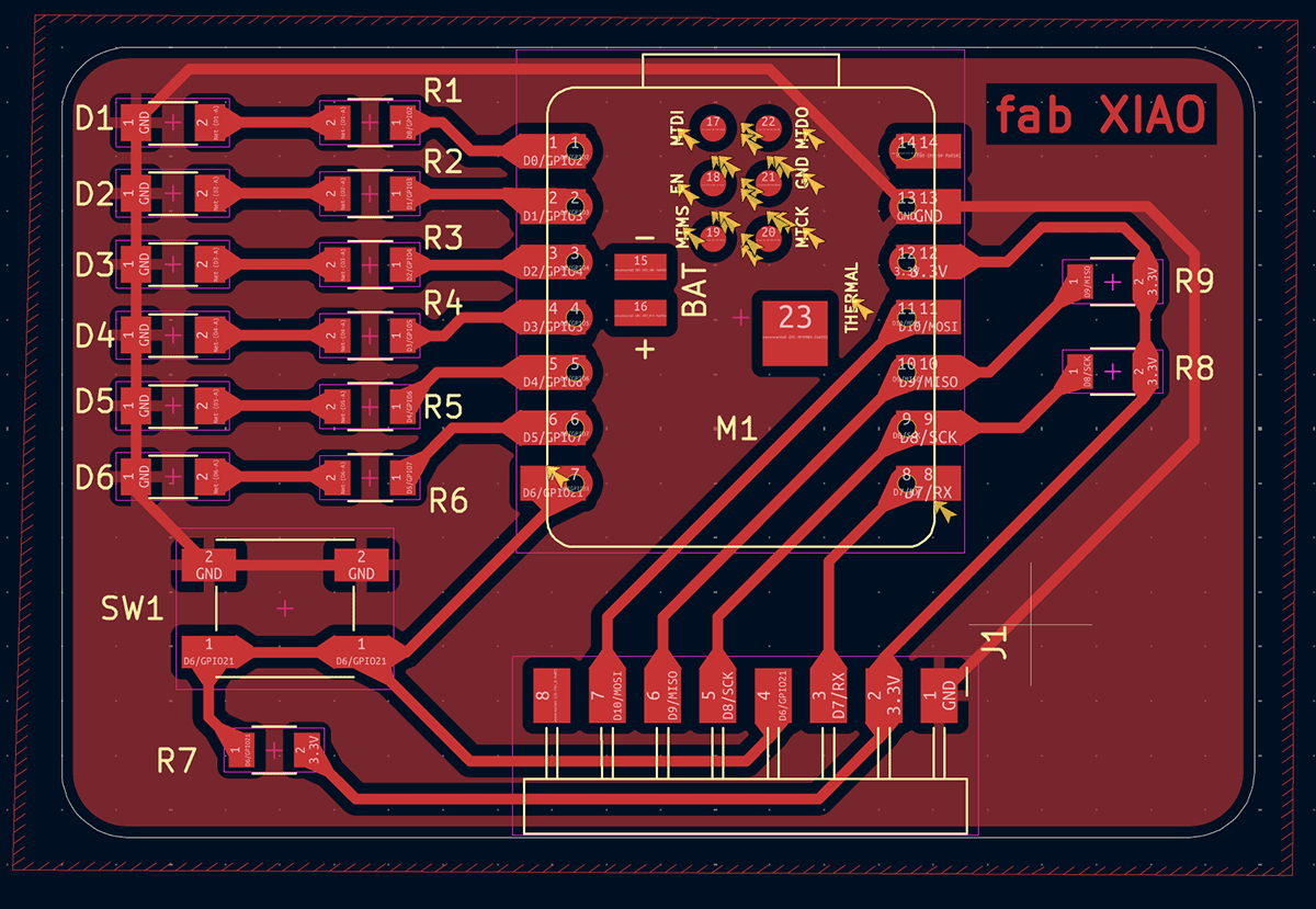
PCB design file prepared during Week 6 individual assignment
Materials and Tools Preparation
Circuit Board Materials
- Single-sided copper-clad board (FR-4, 1.6mm thick)
- Size: approximately 55mm x 36mm
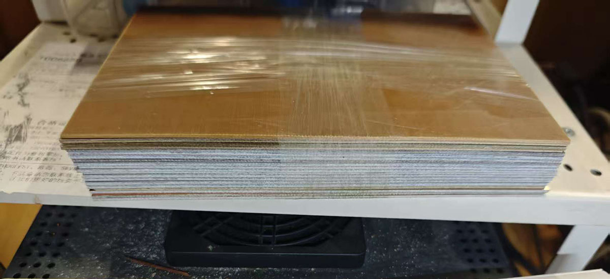
Single-sided copper-clad board prepared by Chaihuo Makerspace for this course
Electronic Components List
As a Seeed employee, I initially thought finding suitable components would be easy, assuming that an electronics product design and manufacturing company would easily meet my needs. According to the BOM list for the XIAO ESP32C3 extension board, I needed the following components:
| No. | Reference | Package | Quantity | Name | Material Preparation Status |
|---|---|---|---|---|---|
| 1 | R1,R6,R3,R4,R5,R2 | R_1206 | 6 | R_1206 220Ω | No |
| 2 | R7,R9,R8 | R_1206 | 3 | R_1206 10KΩ | No |
| 3 | D5,D2,D1,D3,D4,D6 | LED_1206 | 6 | LED_1206 | Yes |
| 4 | J1 | PinHeader_01x08_P2.54mm_Horizontal_SMD | 1 | PinHeader_01x08_P2.54mm_Horizontal_SMD | No |
| 5 | M1 | SeeedStudio_XIAO_ESP32C3 | 1 | Module_XIAO-ESP32C3 | Yes |
| 6 | SW1 | Button_Omron_B3SN_6.0x6.0mm | 1 | Switch_Tactile_Omron | Yes |
Actually finding these tiny components turned out not to be an easy process. Since I designed the circuit board myself, I used some components that were different from those in the fab xiao.
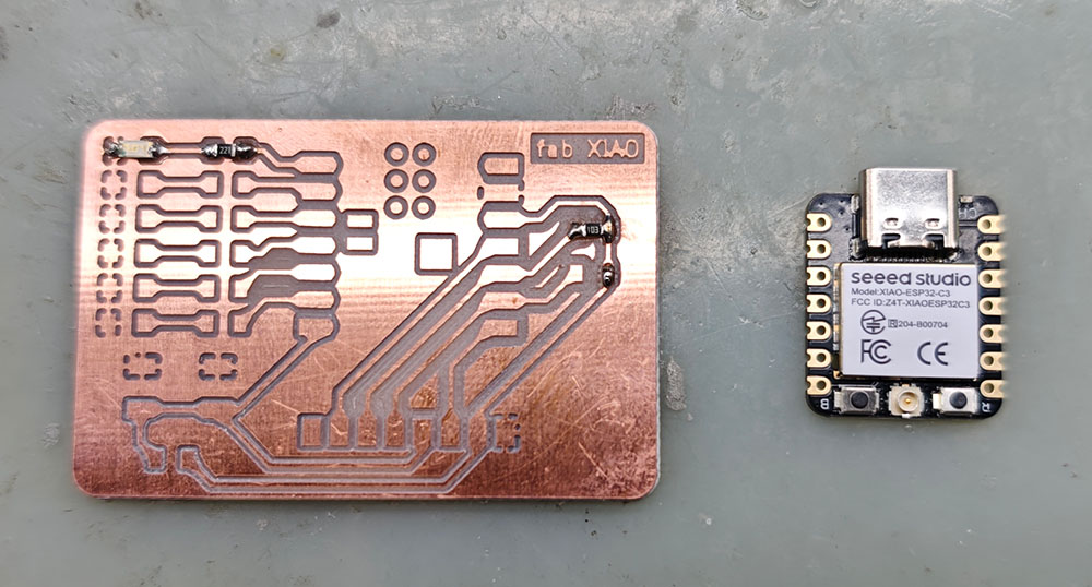
The easiest to find was the Seeed Studio XIAO ESP32C3, these candy-packaged MCUs are everywhere at Seeed.
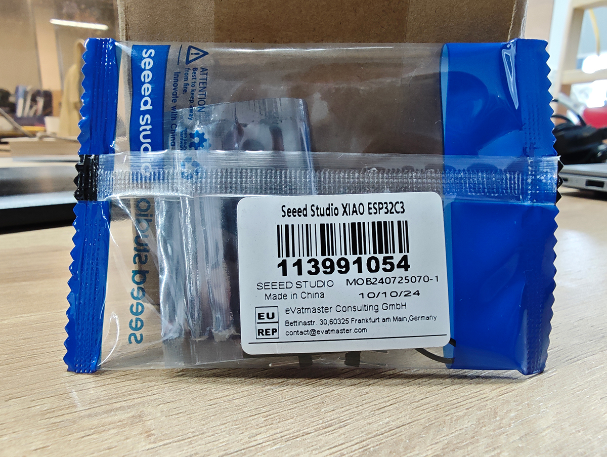
Candy-packaged Seeed Studio XIAO ESP32C3
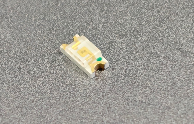
Next were the 1206 specification LEDs, which are available in rolls almost everywhere. I found one without any effort, and the quantity was also sufficient for me. 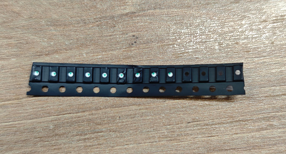
1206 specification LEDs suitable for surface mount packaging
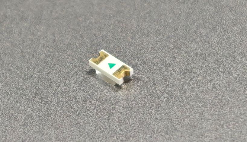
Back of the 1206 specification LED, with directional arrow indicating cathode and anode; pay attention during soldering installation to avoid attaching them backwards
The front of the 1206 specification LED also has a tiny green arrow indicating direction
I quickly found a box of buttons, and what I wanted was inside (the type in the upper right) 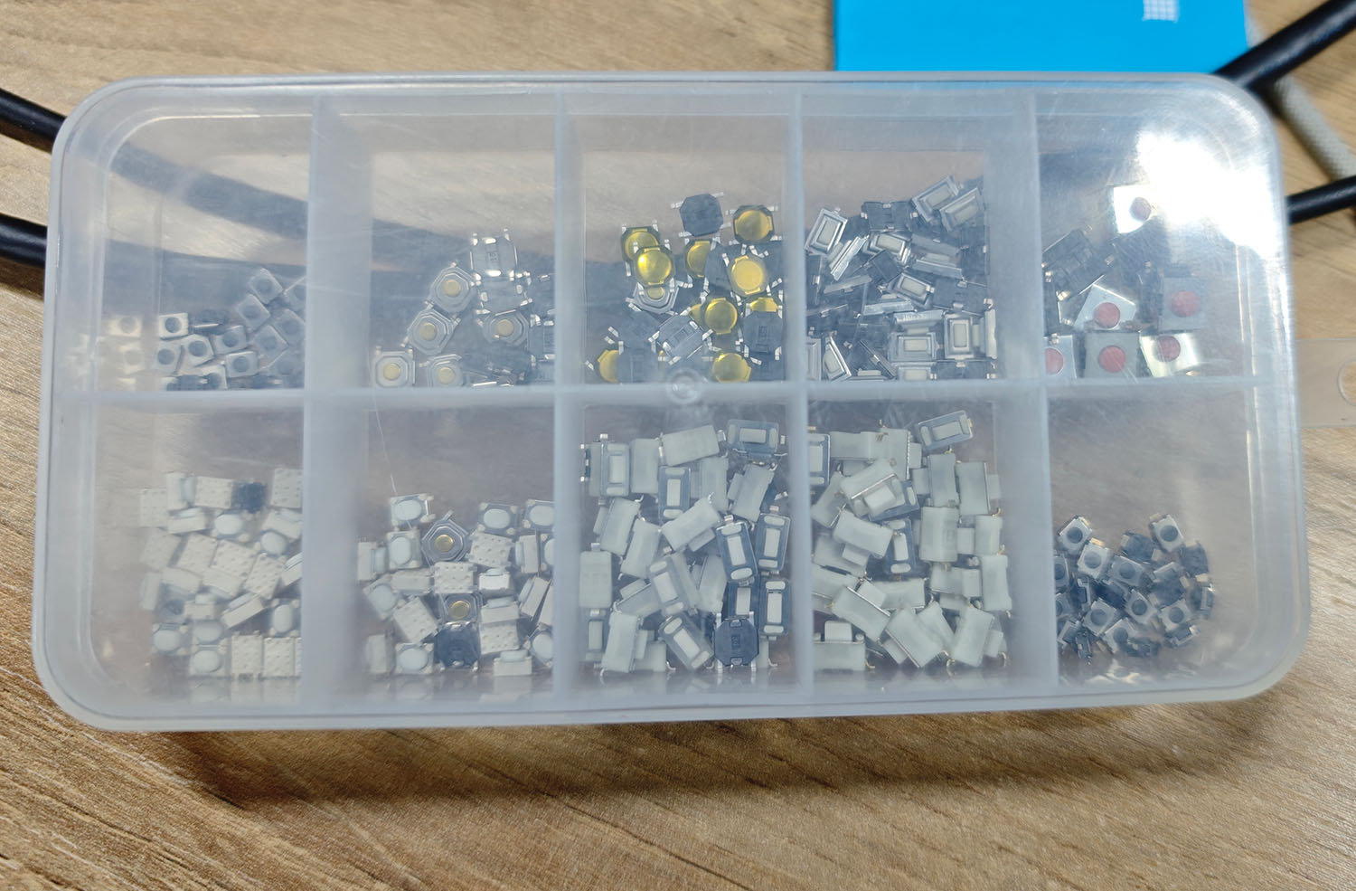
Found a box with various types of buttons
But I couldn't find a suitable PinHeader_01x08_P2.54mm_Horizontal anywhere. With limited assignment time, I could only find a close substitute, although I still plan to purchase some that meet the requirements.
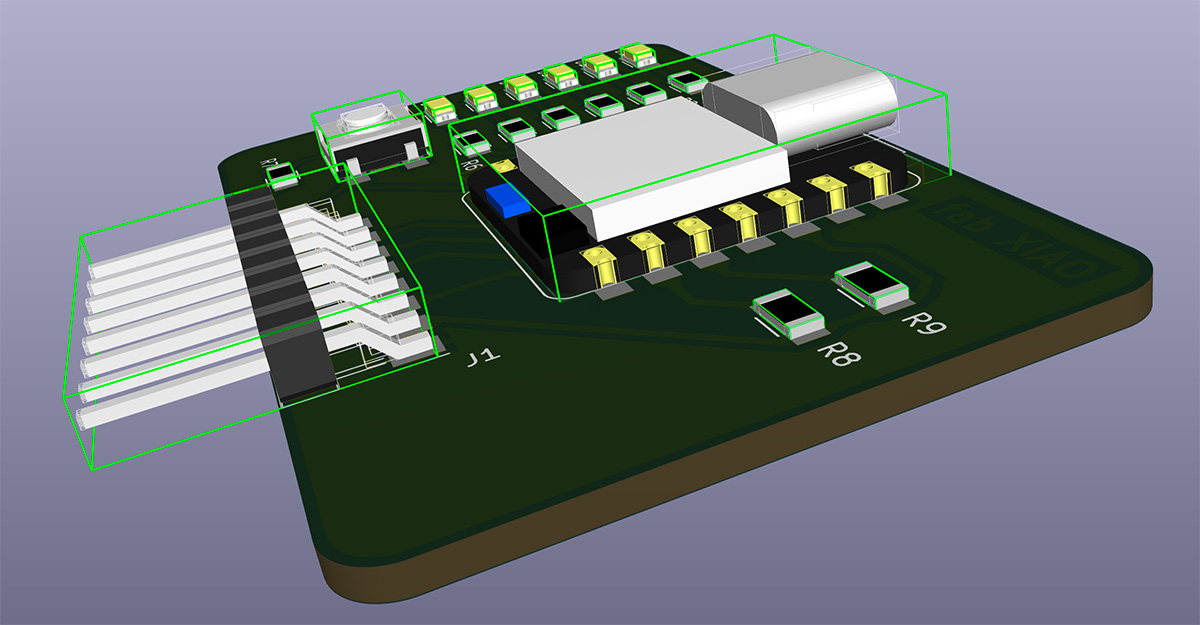
The appearance of the 8-pin header in KiCAD 3D view
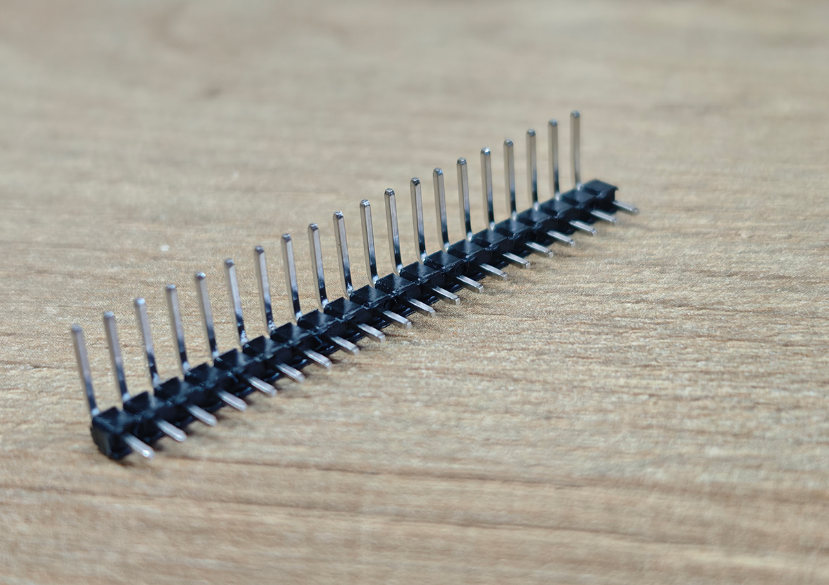
This is the closest pin header I could find, to see if it can be used as a substitute
I encountered difficulties finding R_1206 220Ω and R_1206 10KΩ surface-mount resistors. Seeed engineers said that 1206 specification resistors are too large for most current projects and are rarely purchased or used anymore. They more often use smaller specification resistors and gave me a "heritage" component sample book with smaller 0805 specification resistors. Seeed engineers said these could be substituted, they're just smaller in size. This component sample book starts from 0Ω and gradually increases by resistance value, so I quickly found the 220Ω and 10KΩ resistors I needed.
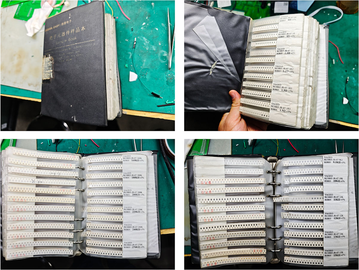
However, they are incredibly smaller than expected. The image below shows a few 10KΩ resistors I took from the sample catalog, unbelievably small.
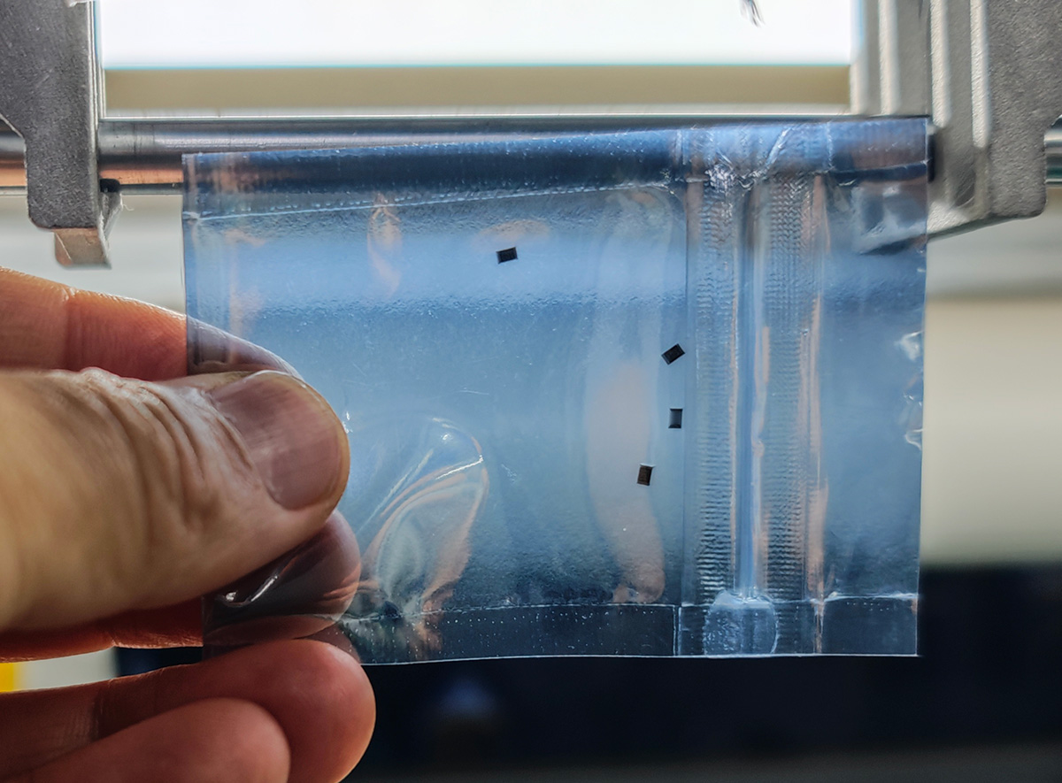
0805 specification resistors taken from the sample catalog
With components basically gathered, I could start production.
Tools
- CNC cutting machine, with Mash3 control computer
- Soldering iron and soldering tool kit
- Multimeter
- Magnifying glass (for soldering small components)
- Arduino IDE (for programming and testing)
Detailed Workflow
1. Making the Circuit Board
For detailed PCB manufacturing process, please refer to this week's group assignment.
1.1 Preparing G-code Files
In Week 6's circuit design assignment, I completed the PCB design and exported two PNG files:
traces_top_layer_0.png: Copper layer circuit (with copper pour completed)outline_top_layer_1.png: Circuit board outline cutting line
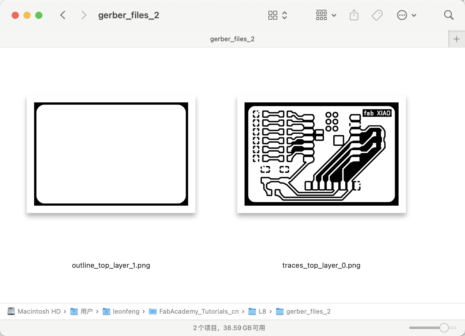
PNG files output from Week 6 individual assignment PCB design
Used the Mods project website to convert these PNG images to G-code:
- Imported
traces_top_layer_0.png, using "isolate traces (1/64)" settings - Generated
traces_top_layer_0.png.ncfile
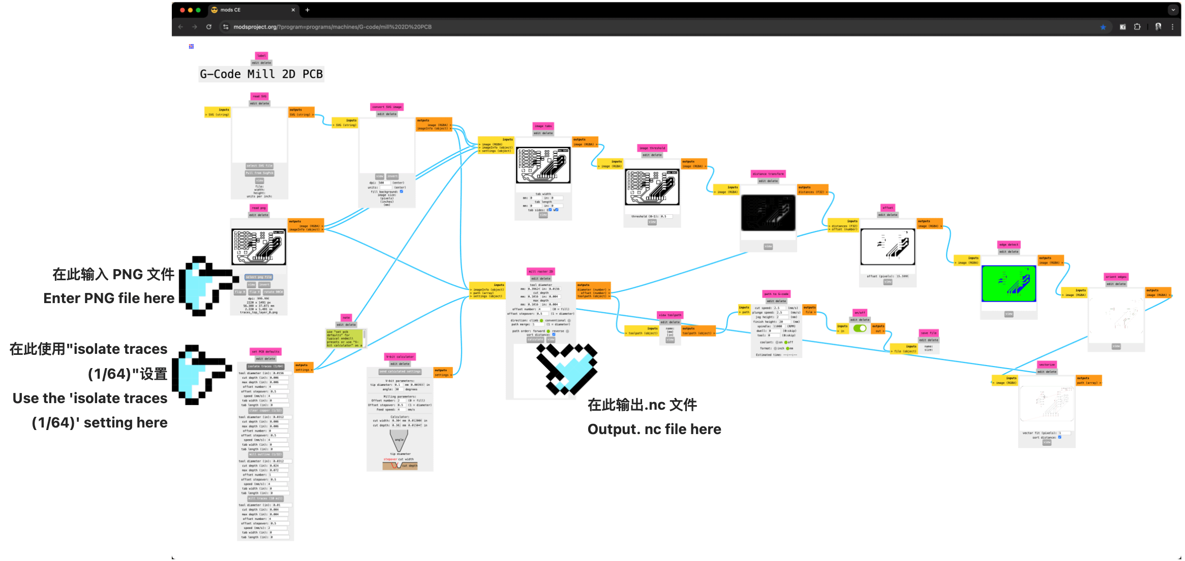
Importing
traces_top_layer_0.png, using "isolate traces (1/64)" settings, and instructions for where the .nc file is generated
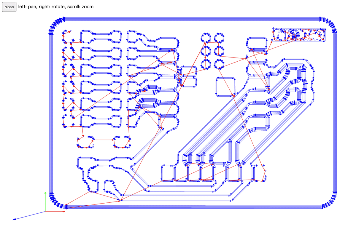
Generated cutting path for the circuit portion
- Imported
outline_top_layer_1.png, using "mill outline (1/32)" settings - Generated
outline_top_layer_1.png.ncfile
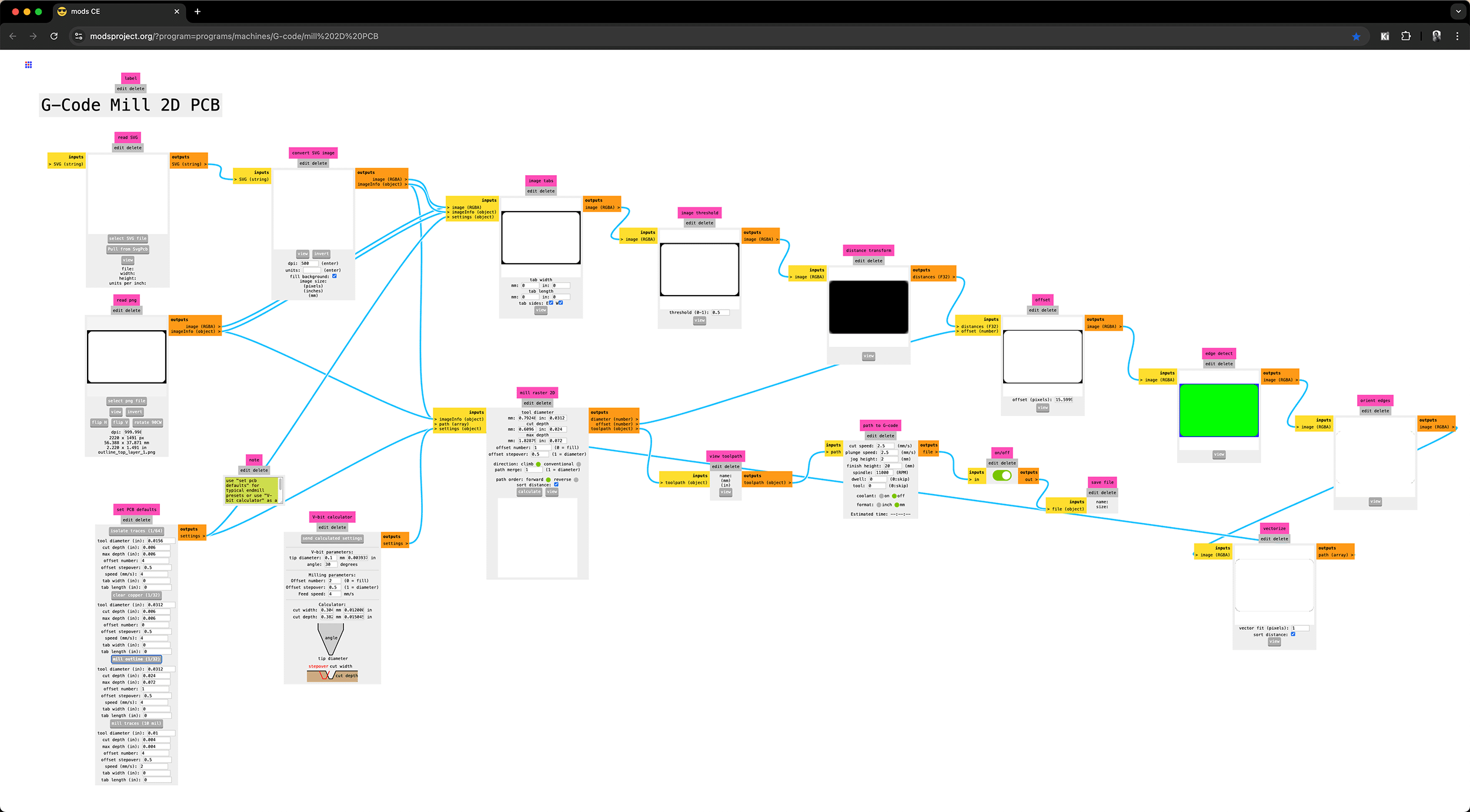
Importing
outline_top_layer_1.png, using "mill outline (1/32)" settings, generating .nc file

Generated cutting path for the outline portion
1.2 CNC Cutting Process
After resolving the CNC machine connection issues in this week's group assignment, I performed the following steps:
- Securing the PCB board: Used double-sided tape and fixtures to firmly secure the copper board to the CNC workbench.
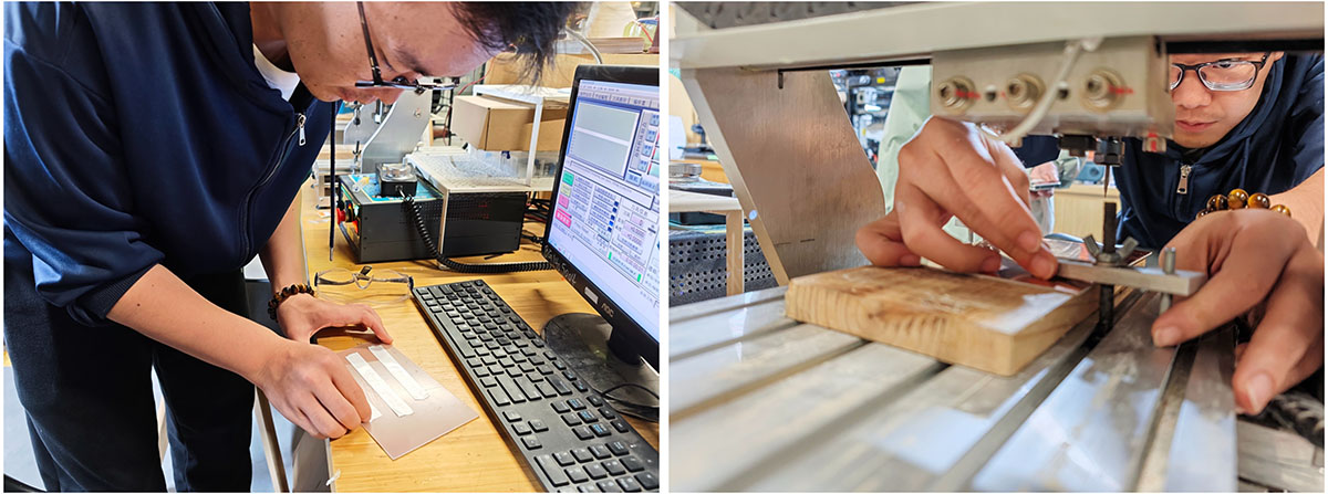
Before cutting the copper-clad board, double-sided tape needs to be applied to the back to fix it more securely on the wooden board serving as a base. The copper-clad board attached to the wooden base must then be secured with fixtures
- Installing cutting tools:
- First installed a 1/64 inch V-shaped bit for cutting circuit traces
- Set the starting position and calibrated the Z-axis height
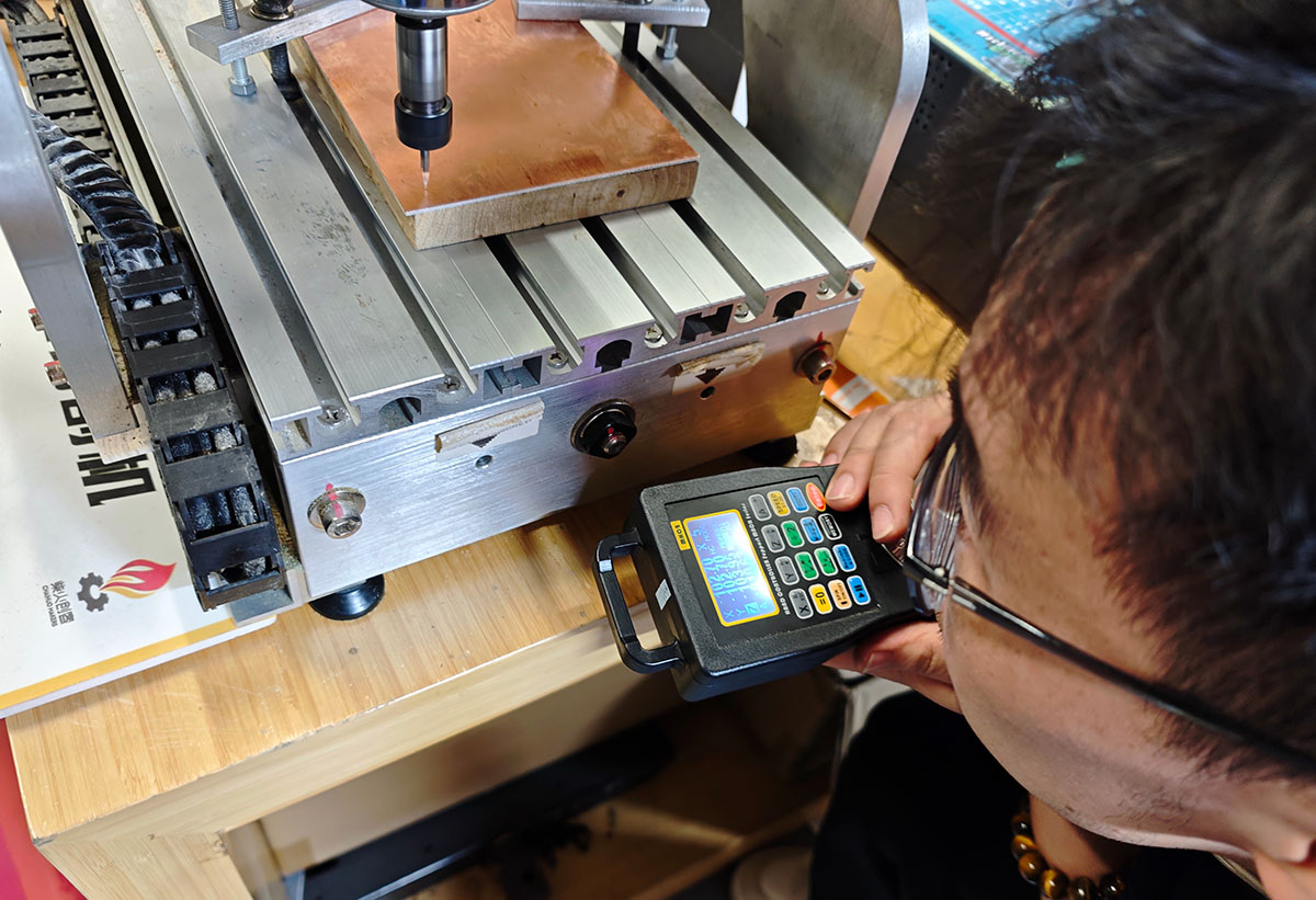
Matthew instructing us on how to zero the equipment and calibrate the Z-axis height
- Executing trace cutting:
- Loaded the
traces_top_layer_0.png.ncfile - Started the cutting process and monitored
- The cutting process went very smoothly, with no broken bits or over-cutting
- Loaded the
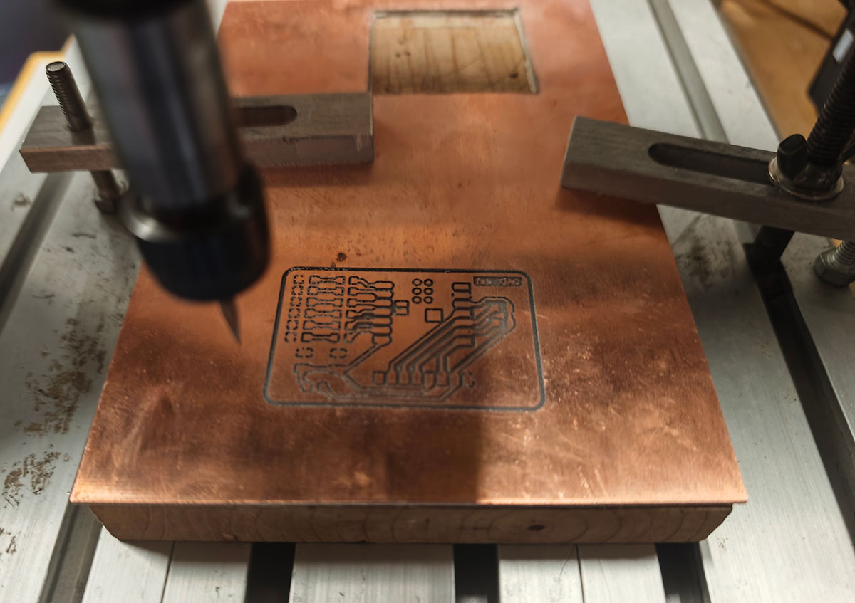
Completed trace cutting. After this step, remember not to move the board
- Changing tools and cutting the outline:
- Installed a 1/32 inch straight slot end mill
- Recalibrated the Z-axis height
- Loaded the
outline_top_layer_1.png.ncfile - Executed outline cutting
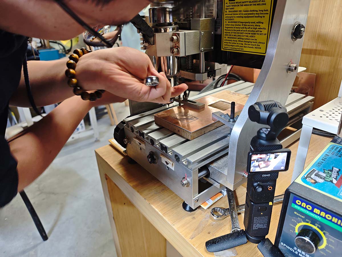
Replacing with the 1/32 inch (0.8mm) straight slot end mill
Used straight slot end mill to cut the circuit board outline.
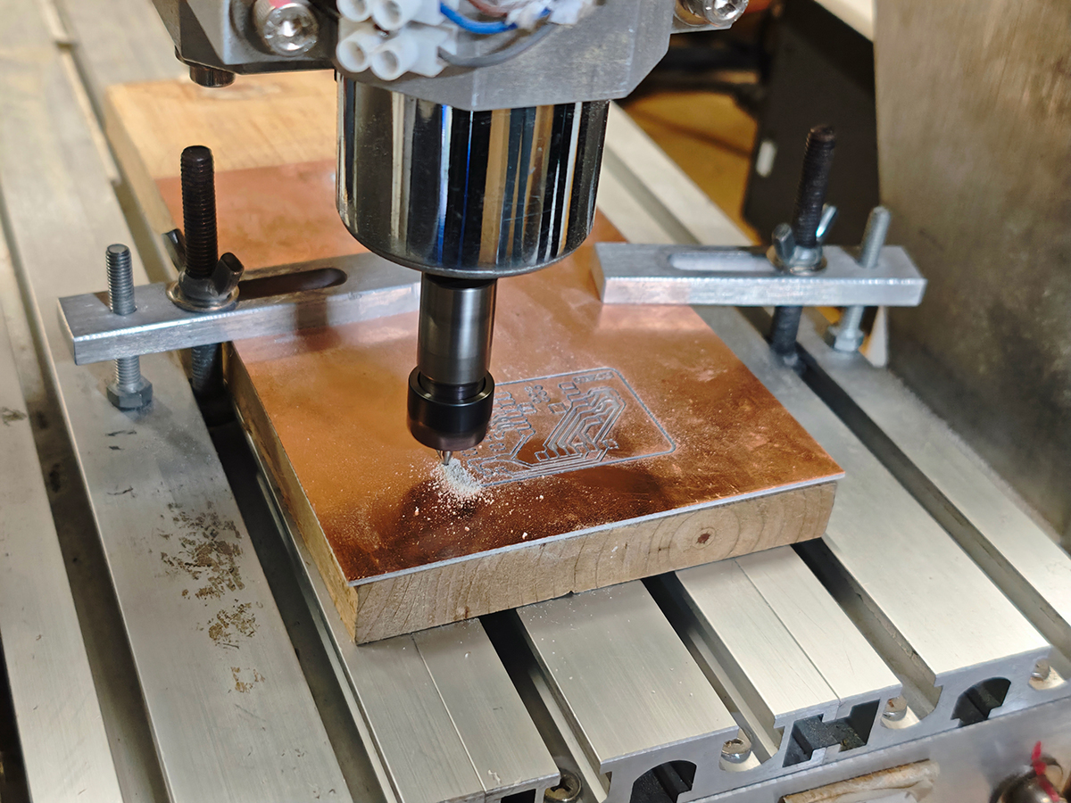
Cutting the outline is deeper and produces more debris
- Cleaning and inspection:
- Used sandpaper to gently sand the circuit board edges, removing burrs
- Inspected trace quality with a magnifying glass, ensuring no short circuits or open circuits
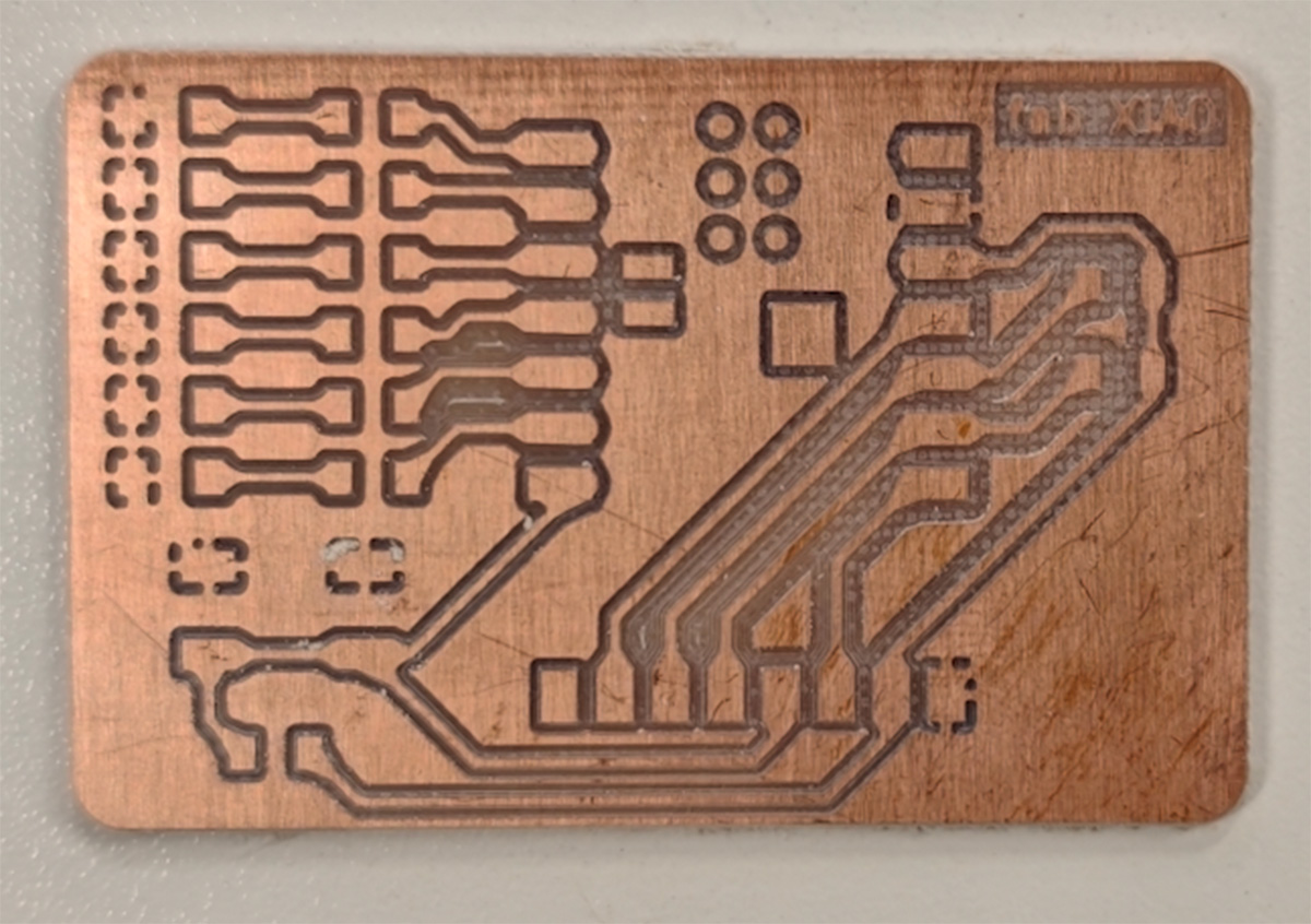
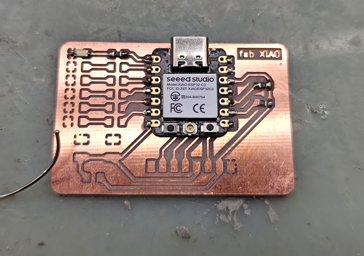
Completed XIAO ESP32C3 extension board
JLCPCB produced PCB
In this week's group assignment, I also experienced the process of online ordering for PCB production; those interested can read that part of the content.
So this week I received two versions of the result.
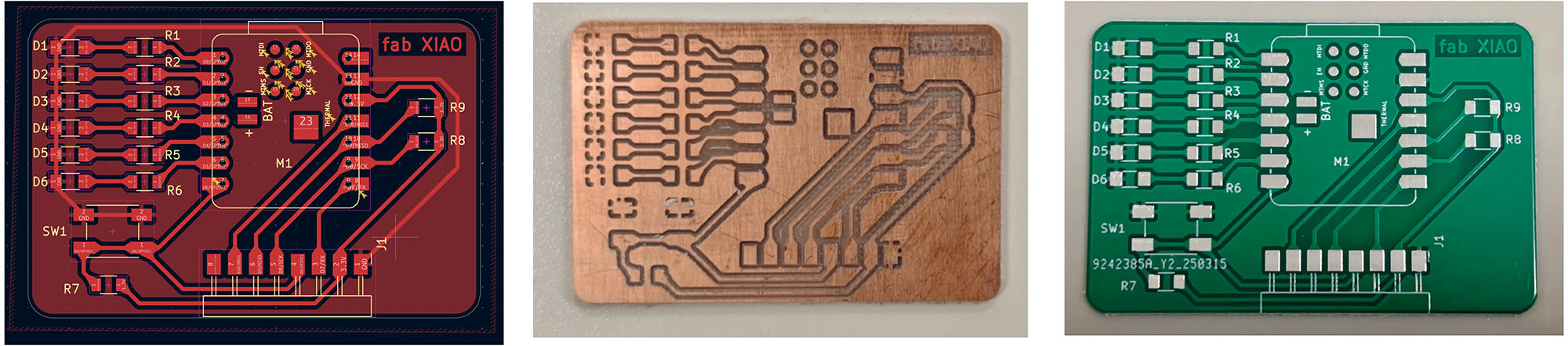
PCB produced using milling process (middle) and PCB produced using etching process (mass production mode)
2. Component Soldering
Since the PCB milling took a lot of time, I could only take advantage of Tuesday evening after Seeed hardware engineers got off work to solder at their workstations, which had the benefit of being fully equipped.
2.1 Preparation
- Organized all components and confirmed they matched the BOM list
- Preheated the soldering iron to about 320°C (suitable for solder paste melting point)
- Prepared flux and solder wire
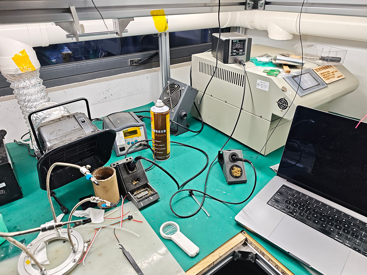
Soldering station used by Seeed hardware engineers, preparing components, soldering iron, and magnifying glass (multimeter not shown in the photo) before soldering, which will also be needed frequently during the soldering process
2.2 Soldering Sequence
I soldered according to the principle of small to large, low to high:
- First soldered the resistors:
- 220Ω resistors (R1,R2,R3,R4,R5,R6) for LED current limiting
- 10KΩ resistors (R7,R8,R9) for button pull-up
- Soldering the XIAO ESP32C3 module (M1):
- Used the method of soldering one side of pins first, confirming correct position before soldering the other side
- During this process, Seeed hardware engineer Qu Xiangnan saw that my soldering technique was not professional and provided valuable guidance
- He taught preheating components, using solder wire for quick connection clicks and other professional techniques, greatly improving subsequent soldering efficiency
Seeed hardware engineer Qu Xiangnan saw that my soldering technique was not professional and taught techniques like preheating components and using solder wire for quick connection clicks
Finally got the XIAO soldered on
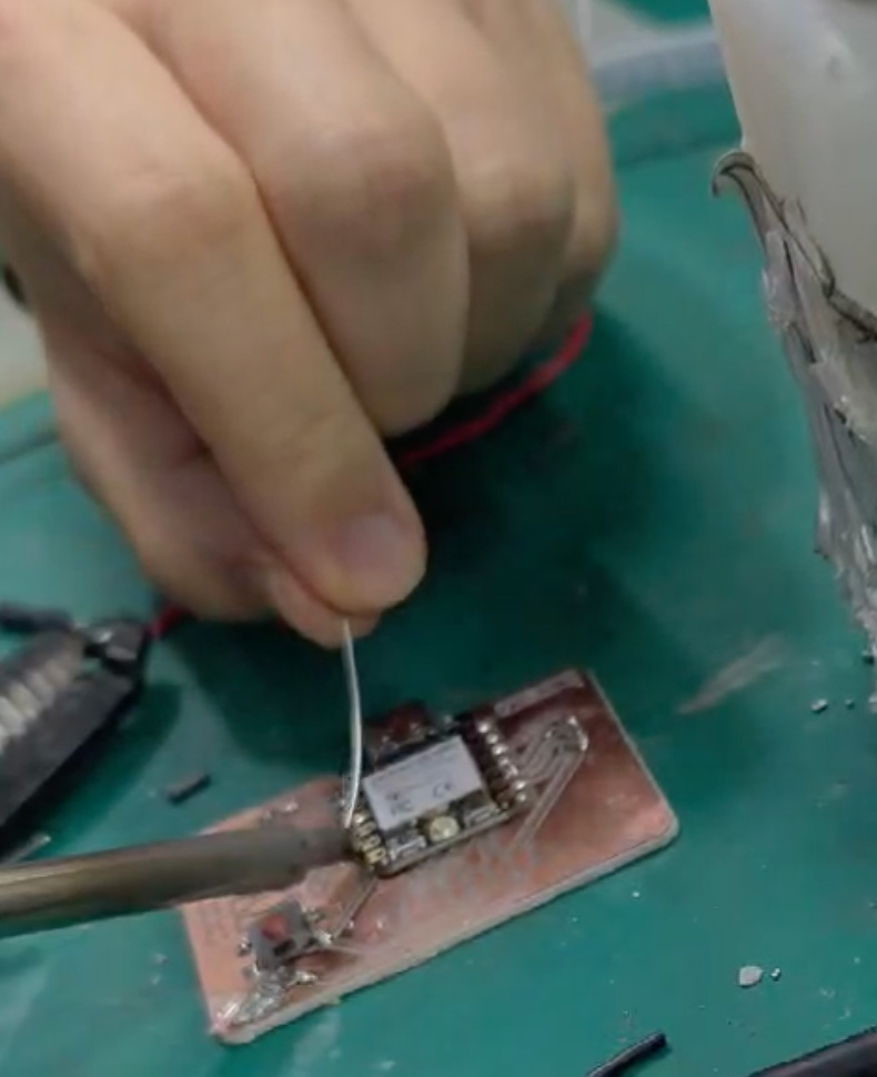
- Soldering the tactile switch (SW1):
- Following Engineer Qu's suggestion, first ensured the switch was placed flat
- Paid attention to force during soldering to avoid damaging the switch structure
- This process was a bit painful, didn't handle the amount of solder well, and it became a mess...
Didn't handle well when soldering the button, used too much solder
Finally managed to solder it on and completed the 3 10KΩ resistors
3. Programming and Testing
Setting up the Programming Environment
- Installed Arduino IDE and XIAO ESP32C3 support package, referring to the official Wiki documentation.
- Configured board options: Selected "XIAO ESP32C3".
- Installed necessary library files.
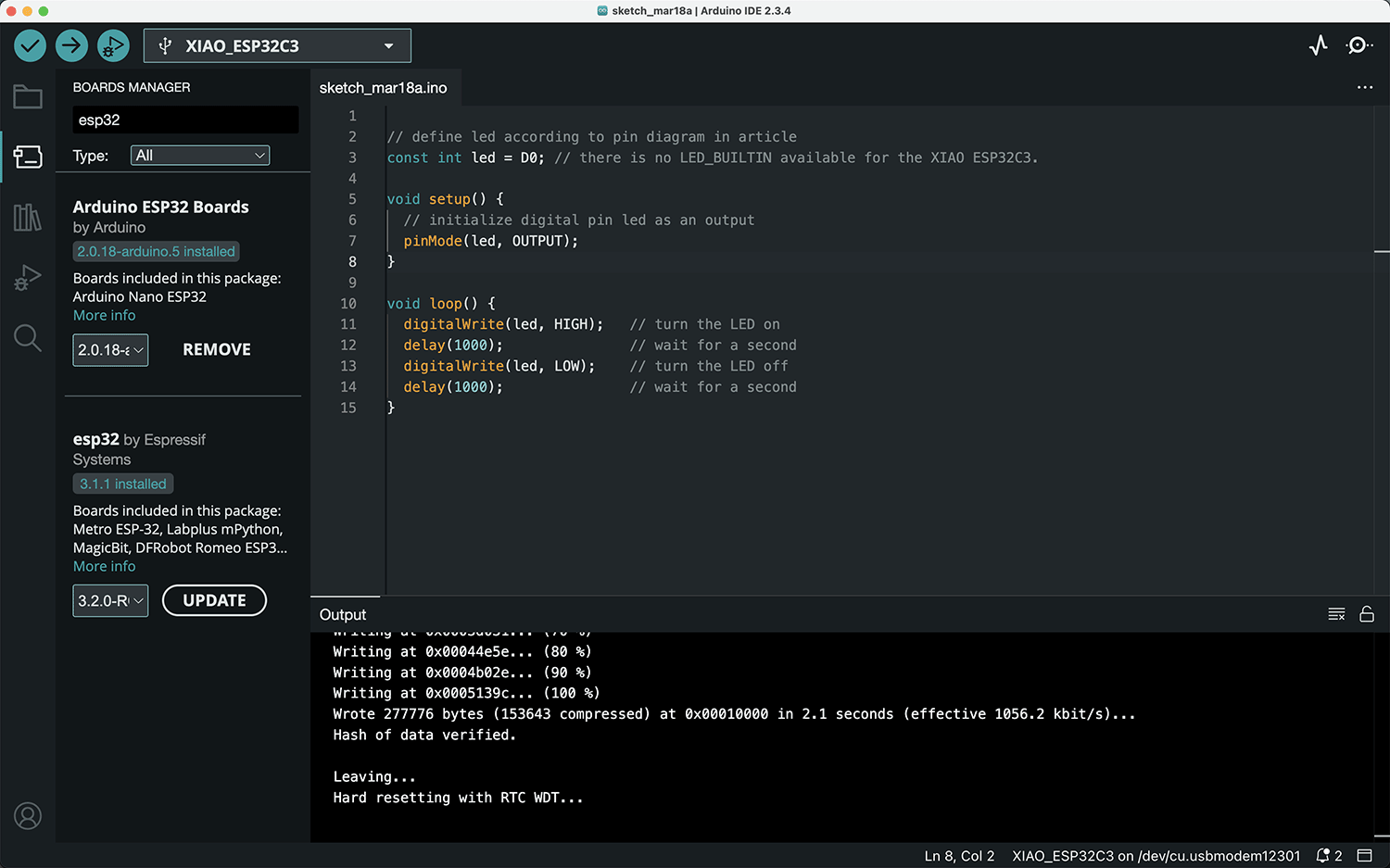
- Initial functionality testing:
- Wrote a simple Blink program to test the soldered
LED(D0).
- Wrote a simple Blink program to test the soldered
// define led according to pin diagram in article
const int led = D0; // there is no LED_BUILTIN available for the XIAO ESP32C3.

void setup() {
    // initialize digital pin led as an output
    pinMode(led, OUTPUT);
}

void loop() {
    digitalWrite(led, HIGH);   // turn the LED on
    delay(1000);               // wait for a second
    digitalWrite(led, LOW);    // turn the LED off
    delay(1000);               // wait for a second
}- Thank goodness, successfully lit up the LED, proving that the basic circuit and solder joints were connected properly.
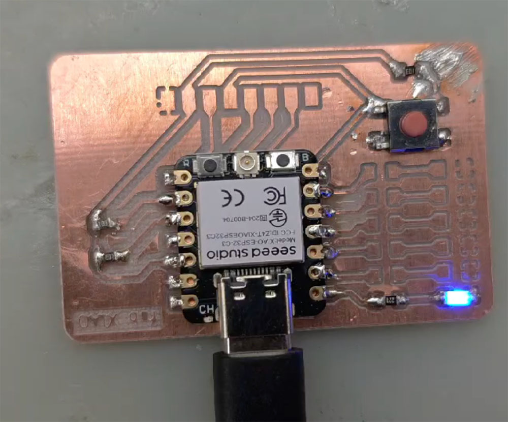
Single LED successfully lit
4. Continued Expansion of Soldering:
- Continued soldering work late at night, attempted to solder several other LEDs and corresponding resistors (ended up soldering 5 sets)
- Encountered challenges: 0805 specification resistors were too small, making operation difficult
- After completing soldering, found that some resistors might be short-circuited (measured resistance value was 0 with a multimeter)
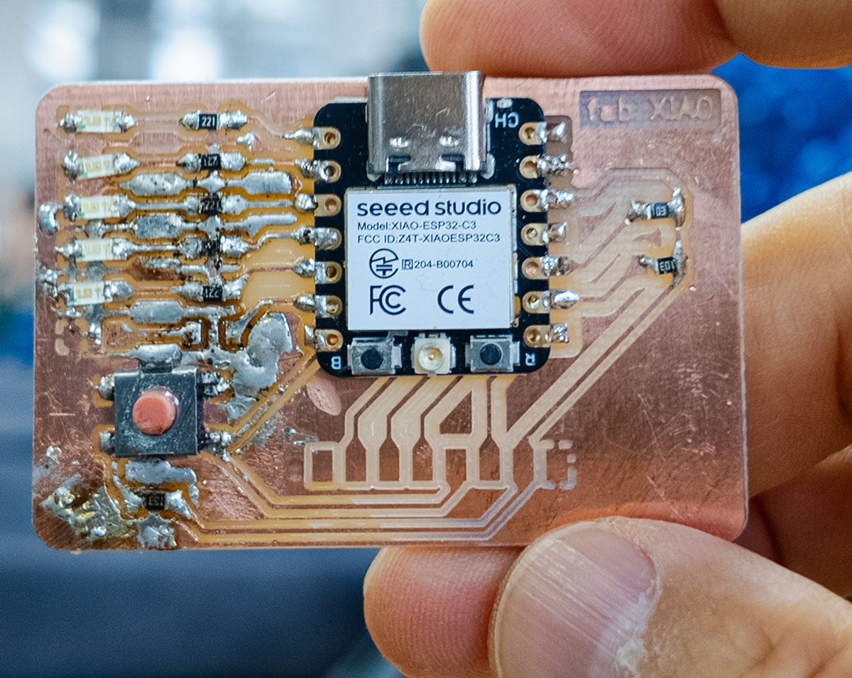
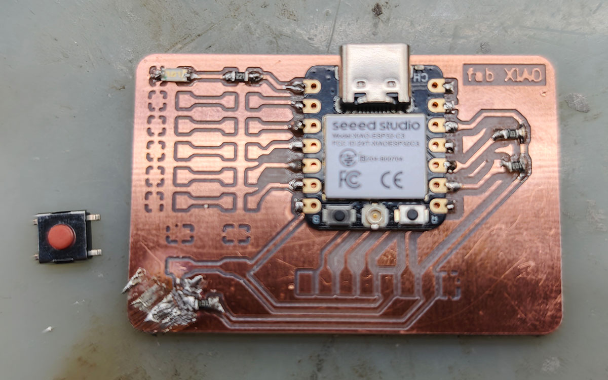
Final progress late Tuesday night, soldered 5 sets of LEDs
Soldering Experience and Difficulties:
- 0805 package SMD components are indeed very small for beginners, requiring a high level of concentration
- Resistors are very easy to short circuit, requiring multiple disassembly and resoldering
- The final completed board, while not aesthetically pleasing, was functionally usable
- Four out of five LEDs worked normally (D0, D1, D3, D4), one (D2) could not light up
Further Test Program
Further rewrote a simple program for 6 LED blinking and button detection:
// Define LED pins D0 through D5 on XIAO ESP32C3
const int ledPins[] = {D0, D1, D2, D3, D4, D5};
const int numPins = 6; // Total number of LED pins

void setup() {
    // Initialize all LED pins as outputs
    for (int i = 0; i < numPins; i++) {
        pinMode(ledPins[i], OUTPUT);
    }
}

void loop() {
    // Turn all LEDs on
    for (int i = 0; i < numPins; i++) {
        digitalWrite(ledPins[i], HIGH);
    }
    delay(1000); // Wait for a second

    // Turn all LEDs off
    for (int i = 0; i < numPins; i++) {
        digitalWrite(ledPins[i], LOW);
    }
    delay(1000); // Wait for a second
}
Back home testing the 5 installed LEDs with the rewritten Blink program, found one red one mixed in, and one not lighting up
5. Test Program Including Button
Continued writing a test program that includes the button:
// XIAO ESP32C3 Extension Board Test Program
// Make LED indicators blink and detect button status

// Define LED pins
const int LED_PINS[] = {D0, D1, D2, D3, D4, D5};
const int LED_COUNT = 6;
const int BUTTON_PIN = D6; // Pin connected to tactile switch

int buttonState = 0;

void setup() {
  // Initialize LED pins as outputs
  for (int i = 0; i < LED_COUNT; i++) {
    pinMode(LED_PINS[i], OUTPUT);
  }

  // Initialize button pin, enable internal pull-up resistor
  pinMode(BUTTON_PIN, INPUT_PULLUP);

  Serial.begin(115200);
  Serial.println("XIAO ESP32C3 Extension Board Test Program Started");
}

void loop() {
  // Read button status
  buttonState = digitalRead(BUTTON_PIN);

  if (buttonState == LOW) {
    // Button pressed, all LEDs light up simultaneously
    for (int i = 0; i < LED_COUNT; i++) {
      digitalWrite(LED_PINS[i], HIGH);
    }
    Serial.println("Button pressed - All LEDs lit");
  } else {
    // Button not pressed, LEDs light up in sequence
    for (int i = 0; i < LED_COUNT; i++) {
      // Clear all LED states
      for (int j = 0; j < LED_COUNT; j++) {
        digitalWrite(LED_PINS[j], LOW);
      }
      // Light up current LED
      digitalWrite(LED_PINS[i], HIGH);
      delay(200);
    }
  }
}Problems and Solutions
After uploading, the test results were as follows:
- Out of 5 LEDs, only 4 could work normally according to program instructions
- Found that the switch always maintained a pressed state, all LEDs stayed lit, which was also verified by the serial monitor output, suspected the button was not soldered well, resulting in a short circuit situation.
Serial monitor showing the button always in pressed state
The challenge of soldering tiny components is enormous, requiring further practice.
Results and Reflection
Successes
- Successfully used CNC machine to cut out high-quality circuit boards with clear traces and no obvious defects
- Learned and initially mastered SMD component soldering techniques under hardware expert guidance
- Successfully completed soldering of some components (4 LEDs, some resistors, and XIAO module)
- Verified basic functionality through Arduino programming, achieved LED control
Challenges and Shortcomings
- 0805 package SMD components are still very small for beginners, resulting in unstable soldering quality
- Short circuit problems in resistor soldering section, need to further improve soldering techniques
- Did not complete soldering of all components, especially the 8-pin horizontal header
- D2 LED did not work normally, requiring troubleshooting
Future Plans
- Purchase another batch of 1206 specification electronic components for new soldering attempts
- Use professional soldering stations and soldering aids to improve soldering precision
- Complete soldering of all components and conduct comprehensive functional testing
- Record more detailed troubleshooting processes and experiences
Learning Insights
This PCB manufacturing experience gave me a profound understanding of the challenges and joys of electronics manufacturing. CNC cutting PCBs is relatively simple, but component soldering represents a significant technical threshold for beginners. I'm very grateful for the professional guidance provided by Seeed hardware engineer Qu Xiangnan, which greatly helped me understand the key points of SMD soldering.
I realized that electronics manufacturing requires patience, attention to detail, and continuous practice. Although I didn't complete the soldering of all components this time, the experience and skills gained are crucial for future projects.
Reference Resources
- XIAO ESP32C3 Official Documentation
- Arduino ESP32 Programming Guide
- SMD Soldering Techniques Guide
- CNC PCB Manufacturing Best Practices
Thanks again to Seeed Studio hardware engineer Qu Xiangnan for providing on-site guidance.
Reassembling PCB Manufactured by JLCPCB
Not content with the failed soldering experience on the copper-clad board PCB, I purchased suitable 1206 resistors (10K Ω and 220 Ω) and 8-pin right-angle headers.
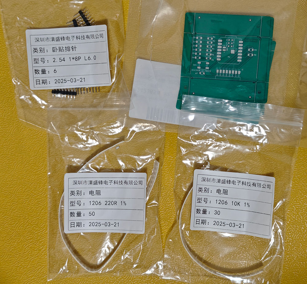
The white-labeled components were newly purchased, prepared for another soldering attempt on the JLCPCB-manufactured PCB
First, I tried soldering a 1206 LED. With the experience from the first PCB, this felt much easier, as shown below.
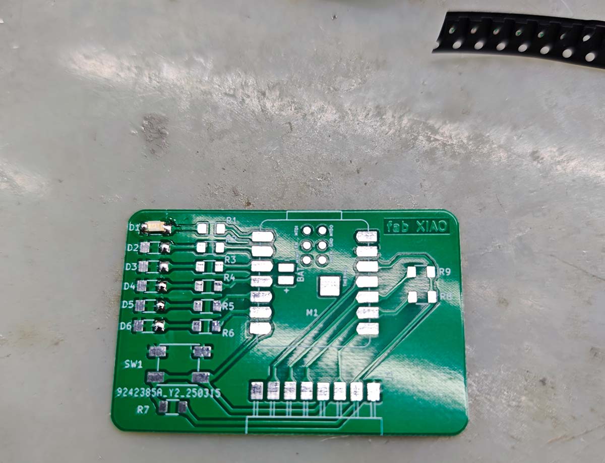
First attempt at soldering a 1206 LED
Because of the solder mask protection layer, the soldering process went very smoothly this time. I didn't spend much time soldering the LED, resistors, button, and right-angle pin headers. During the soldering process, I continuously tested whether the solder points were properly connected. The image below shows testing the button with a multimeter; when pressed, the resistance between the two solder points approaches 0, indicating that the button is working normally.
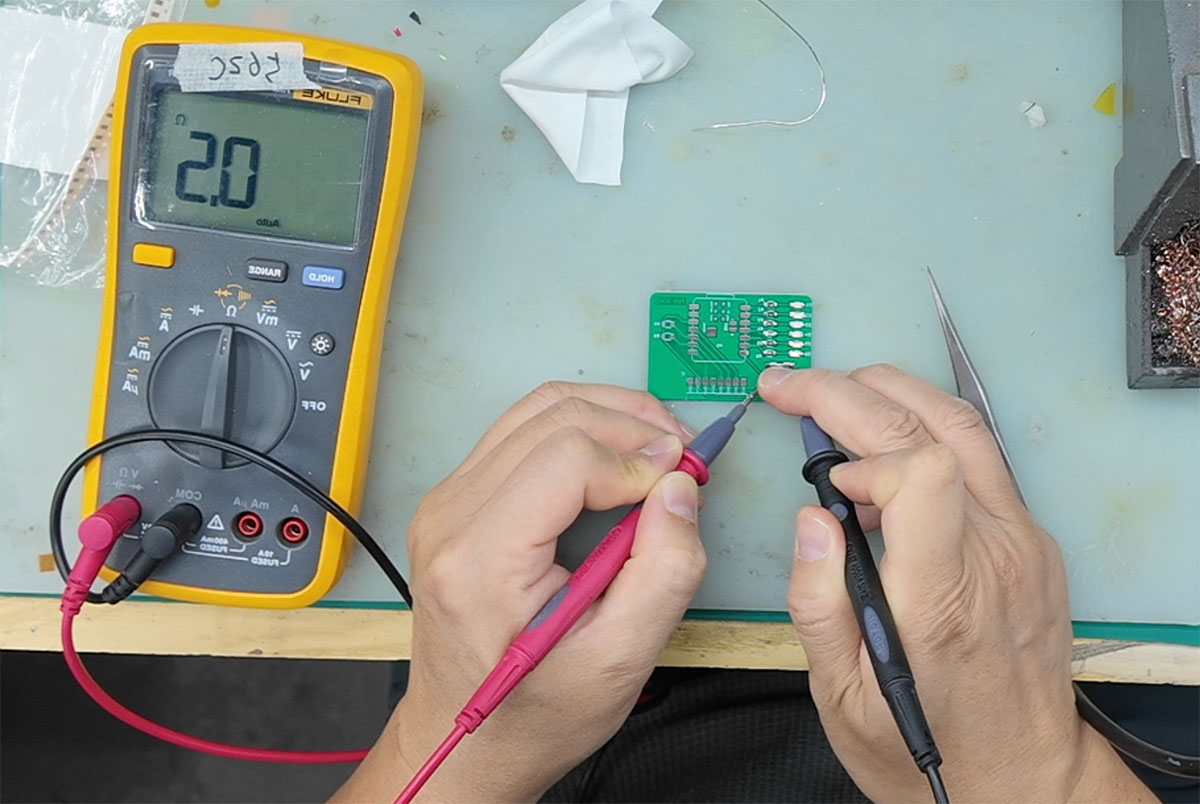
Testing if the circuit connects when the button is pressed
The appearance after all components were soldered is shown below, preparing to solder the XIAO ESP32C3.
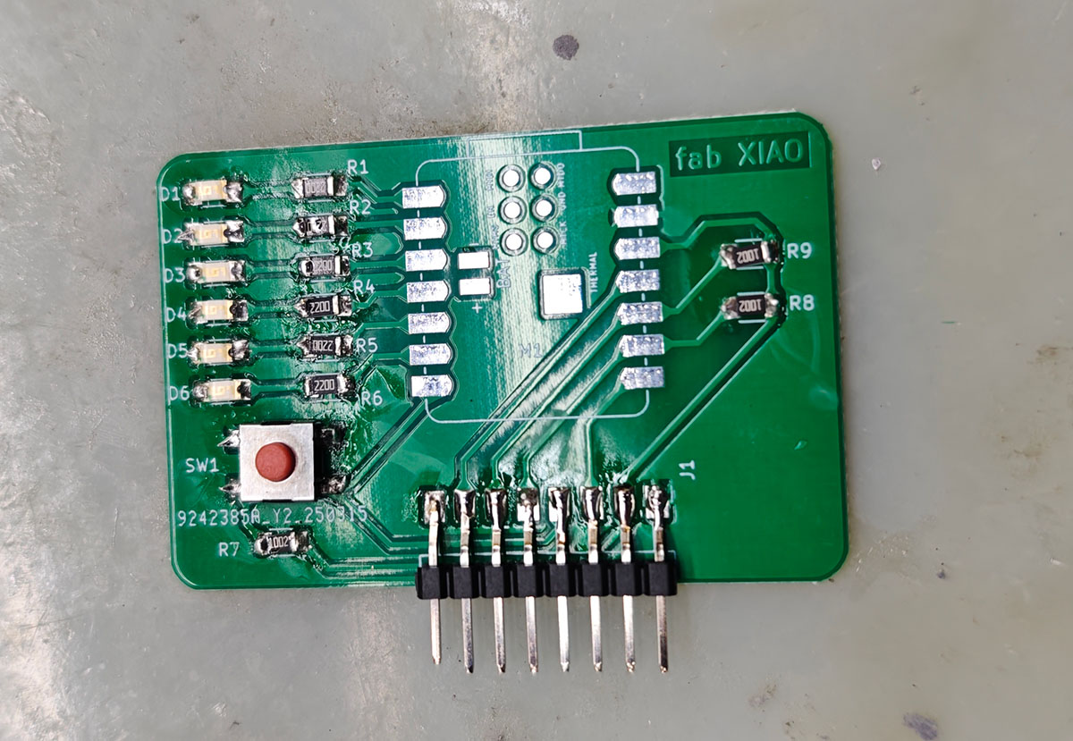
All components soldered, the 1206 resistors were much easier to solder than the 0805 ones used on the previous board
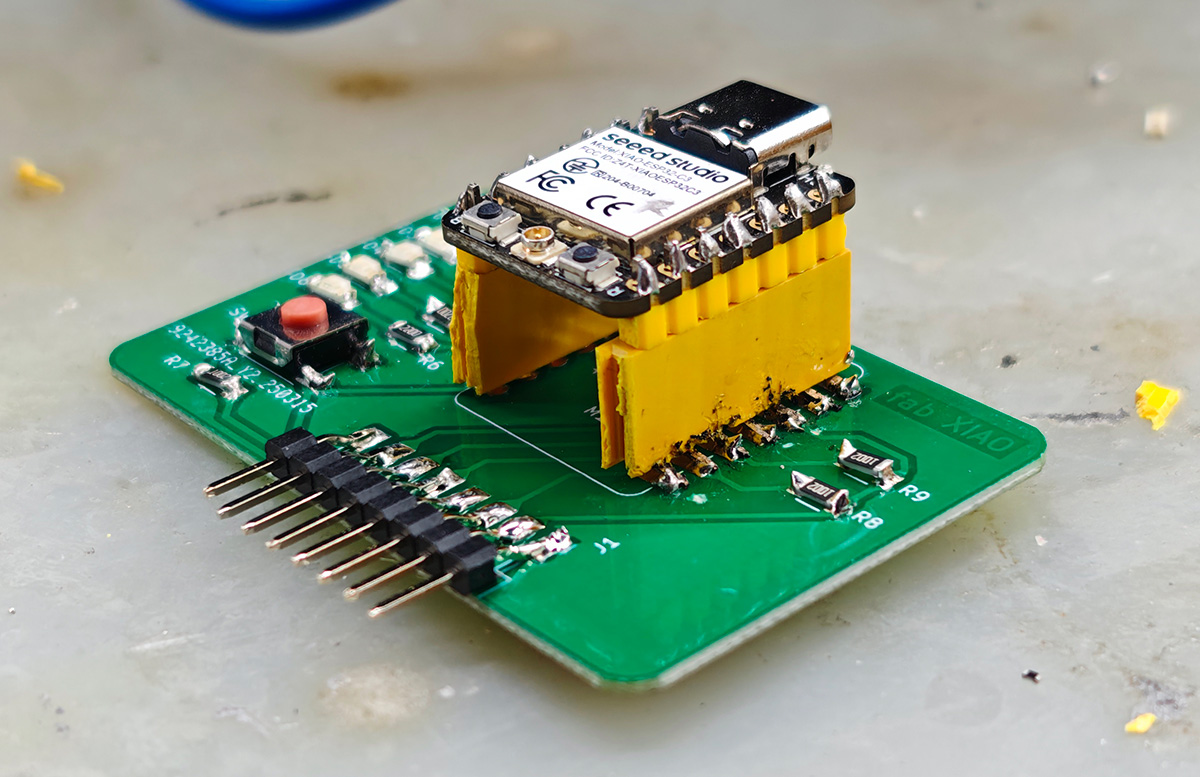
The XIAO ESP32C3 on the previous PCB was permanently soldered to the board, making it difficult to remove for testing. So this time, I considered using a XIAO with pre-soldered pins and found some 8-hole female headers, as shown below.
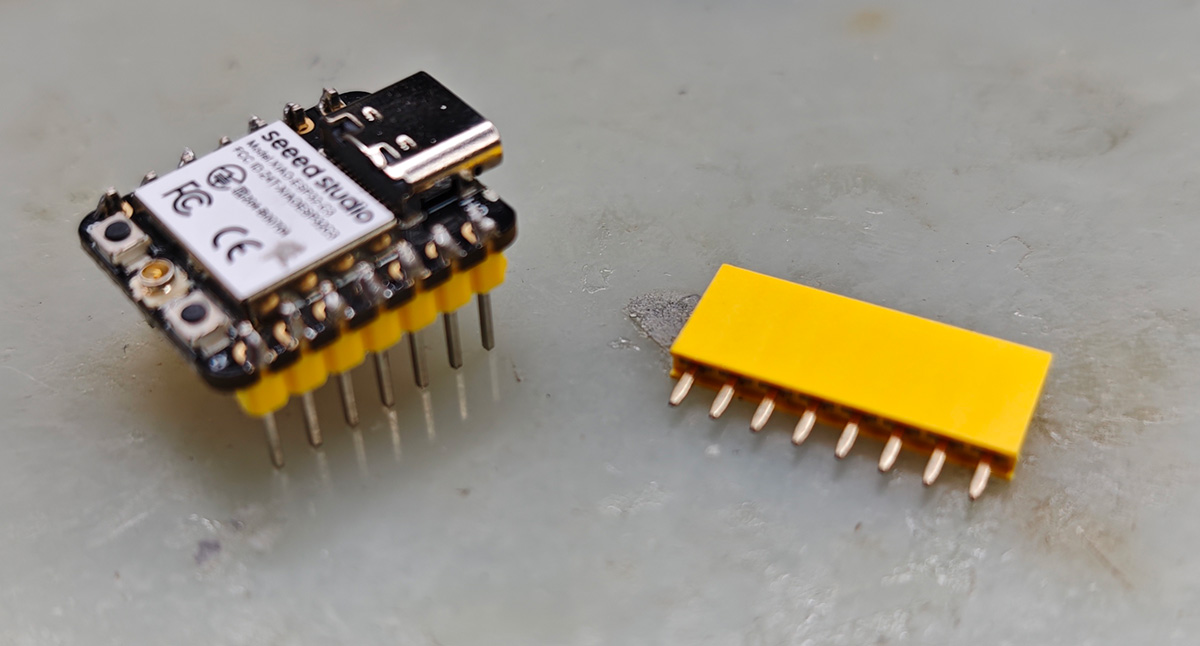
XIAO ESP32C3 with soldered pins and 8-hole female headers
Using pliers, I cut off 1 pin socket, as shown below.
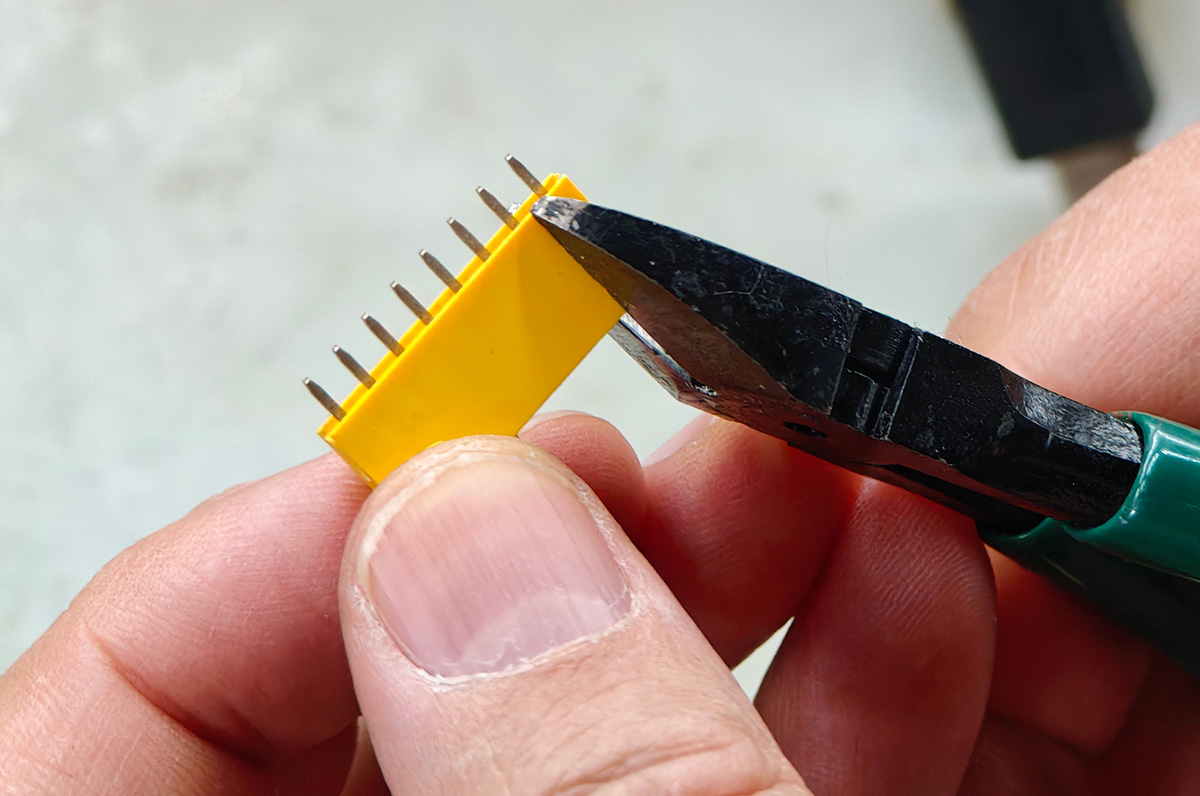
Cutting the 8-hole female header to become a 7-hole female header
Then I bent the pins of the 7-hole female header 90 degrees so it could sit on the PCB (since this batch of PCBs didn't have through-holes). I then placed the XIAO with pins into the female header on the PCB for soldering, as shown below.
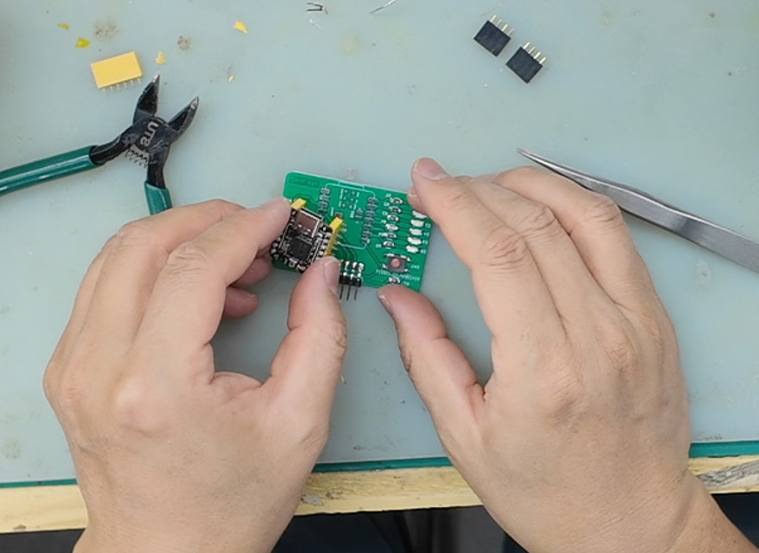
Placing the XIAO with the female header on the PCB to begin soldering
The completed board is shown below, now with a socket for the XIAO.
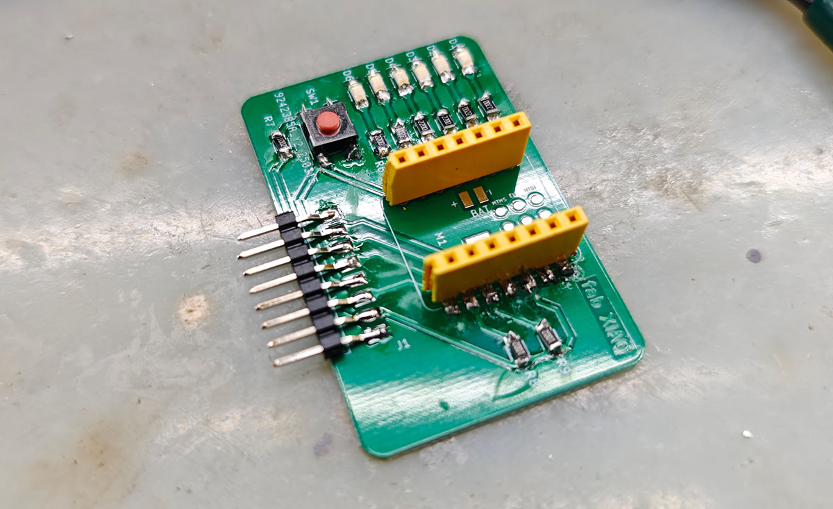
Now with a socket for the XIAO
I directly used the previous test program that included button functionality:
// XIAO ESP32C3 Extension Board Test Program
// Blink LED indicators and detect button status

// Define LED pins
const int LED_PINS[] = {D0, D1, D2, D3, D4, D5};
const int LED_COUNT = 6;
const int BUTTON_PIN = D6; // Pin connected to the tactile switch

int buttonState = 0;

void setup() {
  // Initialize LED pins as outputs
  for (int i = 0; i < LED_COUNT; i++) {
    pinMode(LED_PINS[i], OUTPUT);
  }

  // Initialize button pin with internal pull-up resistor
  pinMode(BUTTON_PIN, INPUT_PULLUP);

  Serial.begin(115200);
  Serial.println("XIAO ESP32C3 Extension Board Test Program Started");
}

void loop() {
  // Read button state
  buttonState = digitalRead(BUTTON_PIN);

  if (buttonState == LOW) {
    // Button pressed, all LEDs light up simultaneously
    for (int i = 0; i < LED_COUNT; i++) {
      digitalWrite(LED_PINS[i], HIGH);
    }
    Serial.println("Button pressed - All LEDs on");
  } else {
    // Button not pressed, LEDs light up in sequence
    for (int i = 0; i < LED_COUNT; i++) {
      // Clear all LED states
      for (int j = 0; j < LED_COUNT; j++) {
        digitalWrite(LED_PINS[j], LOW);
      }
      // Light up current LED
      digitalWrite(LED_PINS[i], HIGH);
      delay(200);
    }
  }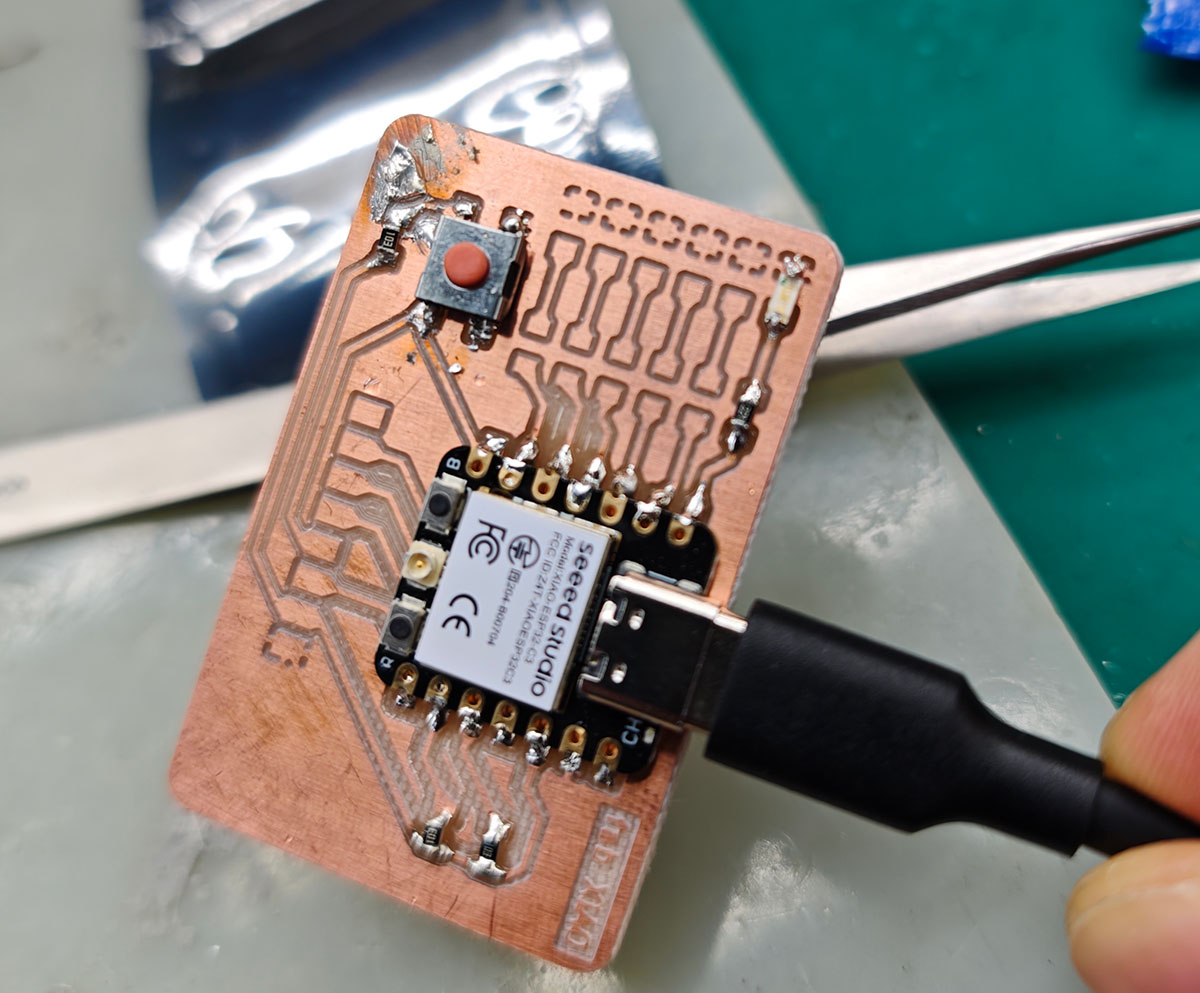
}I plugged in the XIAO ESP32C3, as shown below, and was ready to begin testing.
Inserting the XIAO ESP32C3 into the female header socket
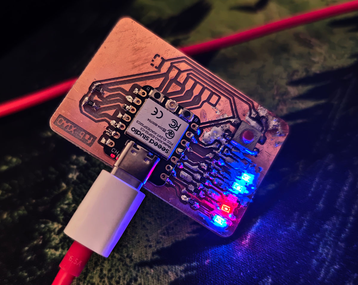
This time it worked perfectly on the first try. When the button is not pressed, the 6 LEDs light up in sequence, as shown below.
When the button is not pressed, the 6 LEDs light up in sequence
When the button is continuously pressed, all LEDs light up simultaneously, as shown below.
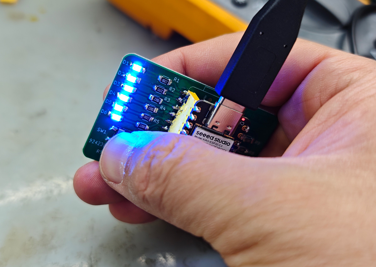
When continuously pressing the button, all LEDs light up simultaneously
Success!