Magical Revolving Lantern
When millennium-old tradition meets digital manufacturing.

Project Overview: Perfect fusion of traditional aesthetics and modern technology
Project Origins
Do you remember the first time you saw a revolving lantern as a child? With flickering candlelight, paper-cut shadows danced gracefully on the lantern cover, as if they had come to life. This ancient toy, dating back to the Han Dynasty, used the simplest physical principle—rising hot air—to create poetic visual experiences.
But as a "digital craftsman" who has been working in Fab Lab for 18 weeks, I couldn't help but wonder: what sparks would fly if this thousand-year-old ancient lamp were given wings of modern technology?
Thus, the Magical Revolving Lantern was born.
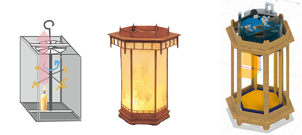
Left: Poetry of traditional revolving lantern; Right: Technological aesthetics of the Magical Revolving Lantern
What Exactly Is It?
Simply put, it's a smart lantern that can "read minds."
Core Features Overview
🎯Precise Rotation Control: Say goodbye to uncontrollable hot air flows, use stepper motors to achieve precise speed control. Want to meditate slowly or party at a fast pace? A gesture does it all.
🌈Programmable Light Magic: 28 WS2812B RGB LEDs arranged in two rows, 360° illumination with no dead angles. From warm candlelight yellow to dreamy rainbow gradients, endless variations at your fingertips.
👋Gesture Recognition: Supports up to three APDS-9960 sensors distributed at 120°, no matter which angle you "interact" with it, it instantly understands your intentions. Up, down, left, right—each gesture has its dedicated light response.
📱Web Remote Control: Phones, computers, tablets—anything that can connect to the internet can control it. During gatherings with friends, everyone can "conduct" the lantern performance together, absolutely becoming the center of attention.
🔗Multi-device Synchronization: Based on MQTT protocol, multiple Magical Revolving Lanterns can form a "lantern array" with synchronized changes—quite a spectacular sight.
Feature Demo: Gesture control, Web interface, synchronization effects
Structural Design
Physical Structure Design
The lantern structure took up a lot of time, as the lantern needs an external frame, an internal rotating structure, and gear mechanisms driven by motors. Integrating these systems together took considerable time.
I used Fusion 360 to design the entire lantern structure, including complex gear systems and assembly design:
- Design file download: https://a360.co/43zU9ao
The rendered effect based on the design file is shown below:
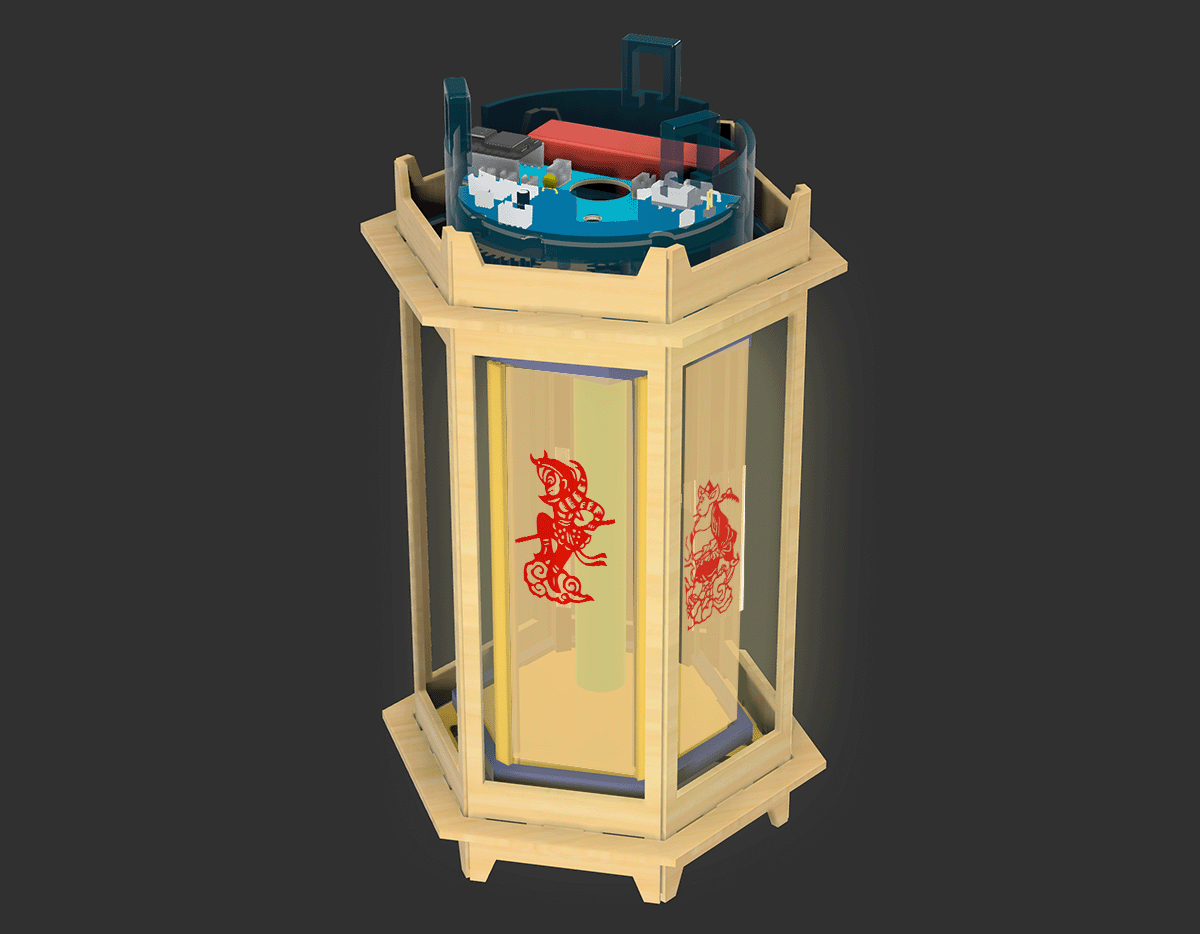
Final design version rendering, designed in Fusion 360
Then I copied a file in Fusion and expanded all structural components as shown in the figure below:
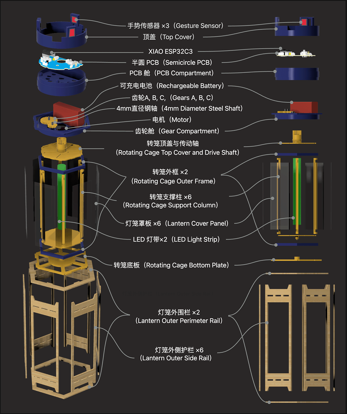
Expanding all components in Fusion 360 and rendering to get the illustration, then I numbered all the structural component files that need to be manufactured
Structural Component List
| Component No. | Part Name | Quantity | Function Description | Manufacturing Method | Material |
|---|---|---|---|---|---|
| Gesture Sensor | 3 | Supports installation of up to 3 gesture sensors to sense gestures from various directions, directly controlling lighting effects and motor rotation | Purchase | ||
| C4 | Top Cover | 1 | Cylindrical, located at the very top of the lantern, with 3 gesture sensor brackets distributed at 120 degrees, nested and fixed with PCB compartment | 3D Printing | PLC/PETG |
| XIAO ESP32C3 | 1 | System core controller | Purchase | ||
| Semicircle PCB | 1 | Electronic hardware development board, positioned in PCB compartment through positioning fixing holes | Milling/JLC Production | Copper Clad Board/FR4 | |
| C3 | PCB Compartment | 1 | Cylindrical structure carrying PCB board, nested and fixed with gear compartment | 3D Printing | PLC/PETG |
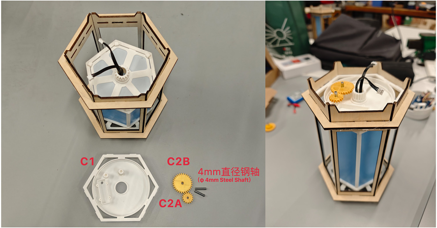
| C2A | Gear A m1.1x16 | 1 | Module 1.1mm, 16 teeth, bore diameter 4.25mm, fixed by 4mm steel shaft; Gear B drives rotating cage shaft gear through Gear A | 3D Printing | PLC |
| C2B | Gear B m1.1x30 | 1 | Module 1.1mm, 30 teeth, bore diameter 4.25mm, fixed by 4mm steel shaft; Gear C drives Gear A through Gear B | 3D Printing | PLC |
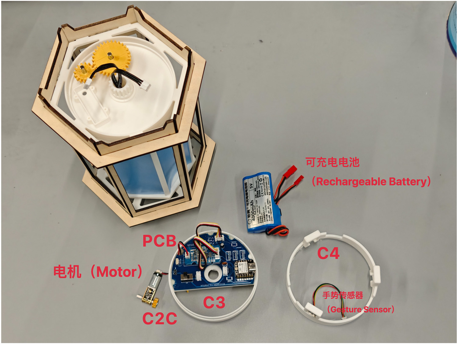
| C2C | Gear C m1.1x8 | 1 | Module 1.1mm, 8 teeth, connected to motor shaft, motor rotation also drives Gear C | 3D Printing | PLC |
| 4mm Diameter Steel Shaft | 2 | Supporting gears | Purchase | ||
| Motor | 1 | Drives gear group, then drives lantern rotating cage | Purchase | ||
| Rechargeable Battery | 1 | Powers the system | Purchase | ||
| C1 | Gear Compartment | 1 | Supports 3 gears, contains motor box and battery compartment; center has round hole for lantern rotating shaft gear to pass through and connect with gears inside gear compartment; fixed with outer rail through slot holes | 3D Printing | PLC/PETG |
| B6 | Rotating Cage Top Cover and Drive Shaft | 1 | Top cover central shaft with gear, driven by Gear A in gear compartment to rotate entire rotating cage | 3D Printing | PLC |
| B5 | Rotating Cage Outer Frame | 2 | Top and bottom of rotating cage each have one, fixing rotating cage top cover, bottom cover and 6 rotating cage support columns | 3D Printing | PLC/PETG |
| LED Light Strip | 2 | Each light strip consists of 14 RGB LEDs | Purchase | ||
| B4 | Rotating Cage Support Column | 6 | Supports rotating cage and fixes lantern cover panels | 3D Printing | PLC |
| B3 | Lantern Cover Panel | 6 | 1mm thick semi-thin panels, 6 panels can have vinyl-cut sticker patterns, customizable DIY according to preferred themes | 3D Printing | PLC/PETG |
| B2 | Rotating Cage Bottom Plate | 1 | Bottom has a conical protrusion that can be placed in cylindrical constraint of lower support base | 3D Printing | PLC |
| B1 | Bottom Bracket of the Cage | 1 | Top has cylindrical fixing hole, fixed with outer rail through slot holes | 3D Printing | PLC |
| A1 | Lantern Outer Side Rail | 6 | Obtained by laser cutting | Laser Cutting | 3mm Wood Board |
| A2 | Lantern Outer Perimeter Rail | 2 | Top and bottom 2 pieces constrain lantern outer side rails | Laser Cutting | 3mm Wood Board |
Component Manufacturing
Manufacturing File Export
According to the numbering, I exported all files needed for manufacturing the structural parts, with the directory structure as follows.
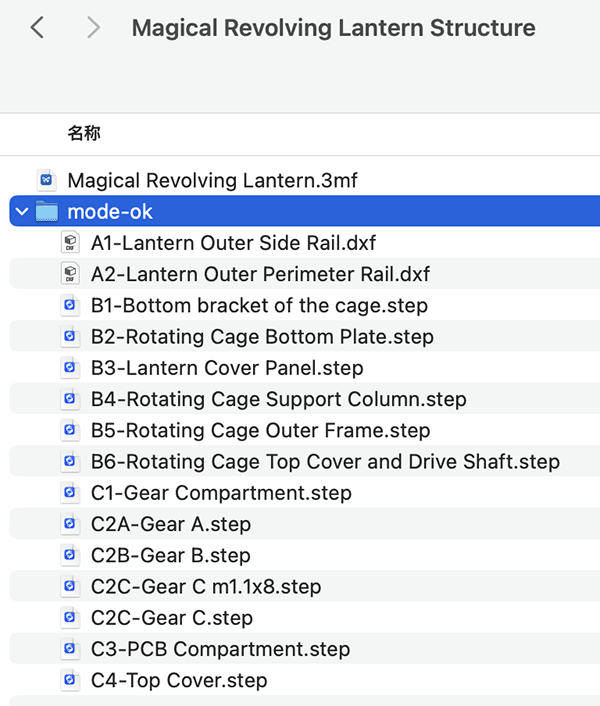
All component files needed for the structural part
Download structure file archive: Magical Revolving Lantern Structure.zip
A1-A2 Laser Cutting
Import A1-Lantern Outer Side Rail.dxf (clone to 6 pieces) and A2-Lantern Outer Perimeter Rail.dxf (clone to 2 pieces) into laser cutting software. For 3mm basswood board, I set 90% laser intensity and processing speed of 15m/s.
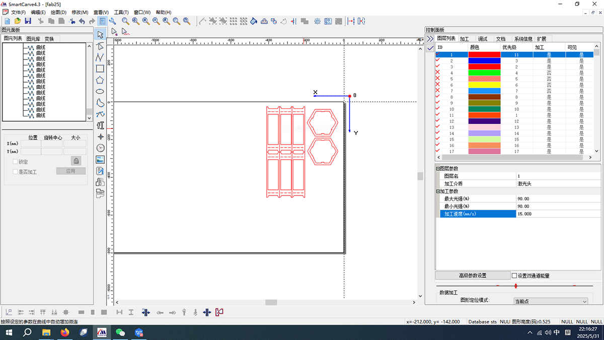
Import A1 and A2 files into laser cutting machine software, clone required quantities, adjust laser energy and speed
Then proceed with cutting.
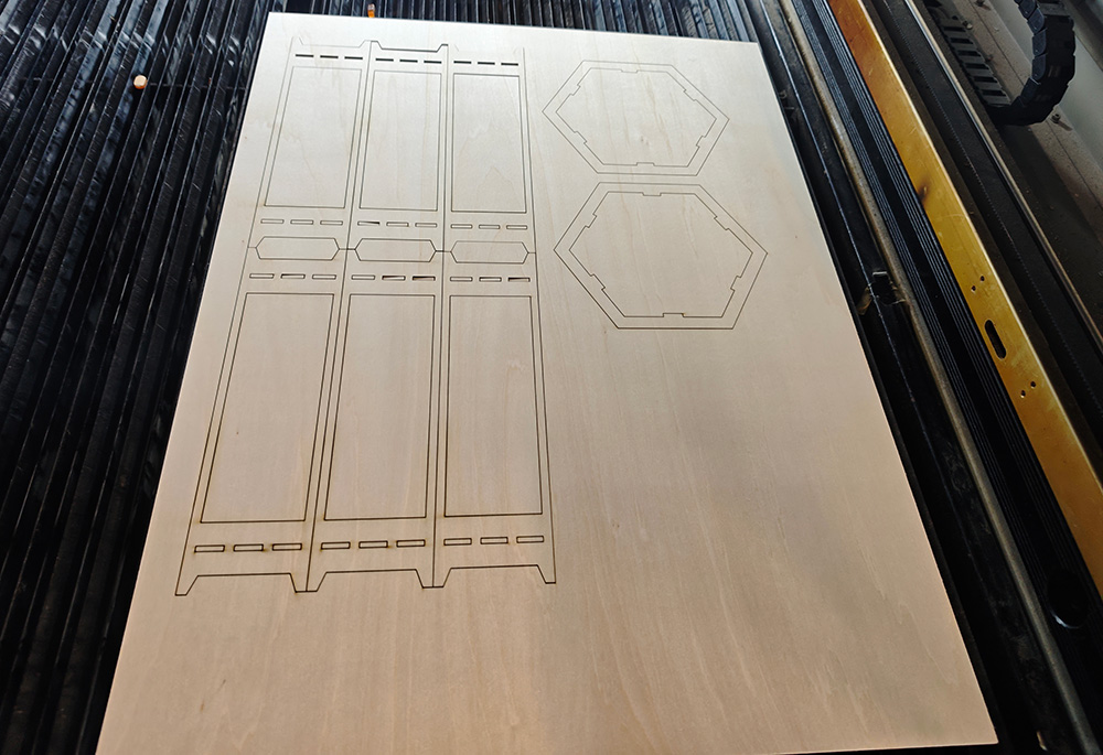
A1-A2 cutting completed
B1-C4 3D Printing
There's a Magical Revolving Lantern.3mf file in the archive, which is a Bambu printer project archive. When opened, you can see the plate distribution effects of all 3D printed parts, convenient for slicing and printing plate by plate.
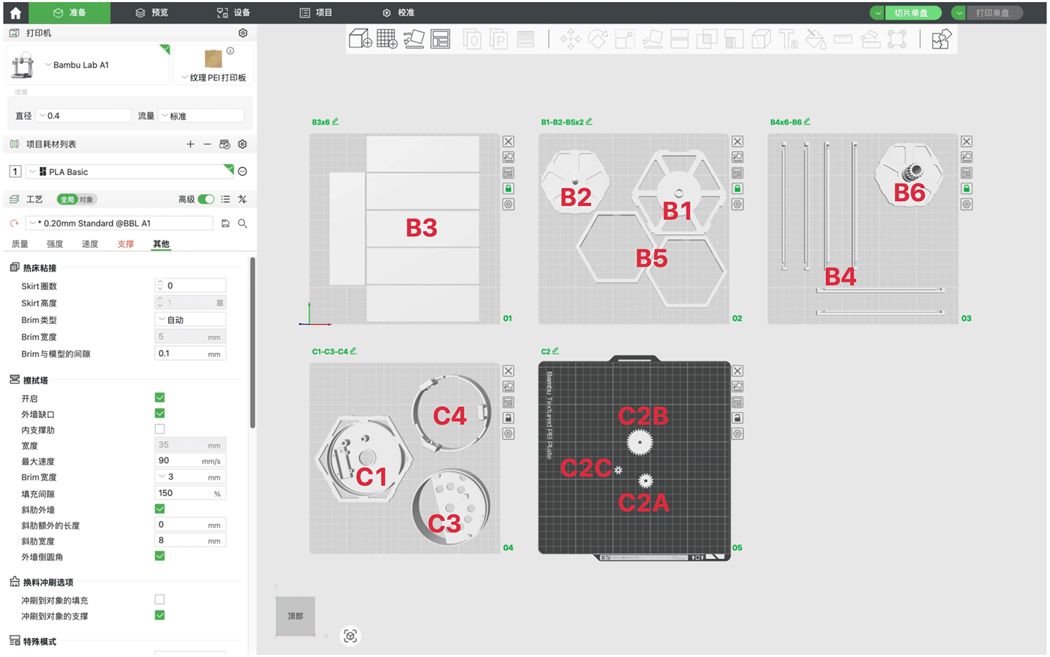
Bambu printer project multi-plate archive
Printing plate by plate, using Bambu LAB A1 printer, I printed all components plate by plate. For B3 lantern cover panels, I used translucent PETE material. For gears, to distinguish them from the gear compartment, I used golden PLA Silk material. Everything else was white PLA material.
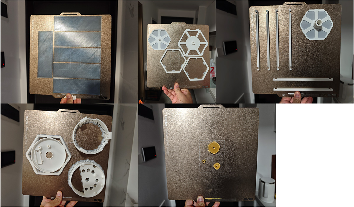
Using Bambu LAB A1 printer, printed all components plate by plate
When printing gears, it's best to use highest quality printing (0.08mm High Quality). I tried it and found that the default 0.2mm makes the holes in the middle of gears smaller, unable to rotate when fitted on 4mm steel shafts.
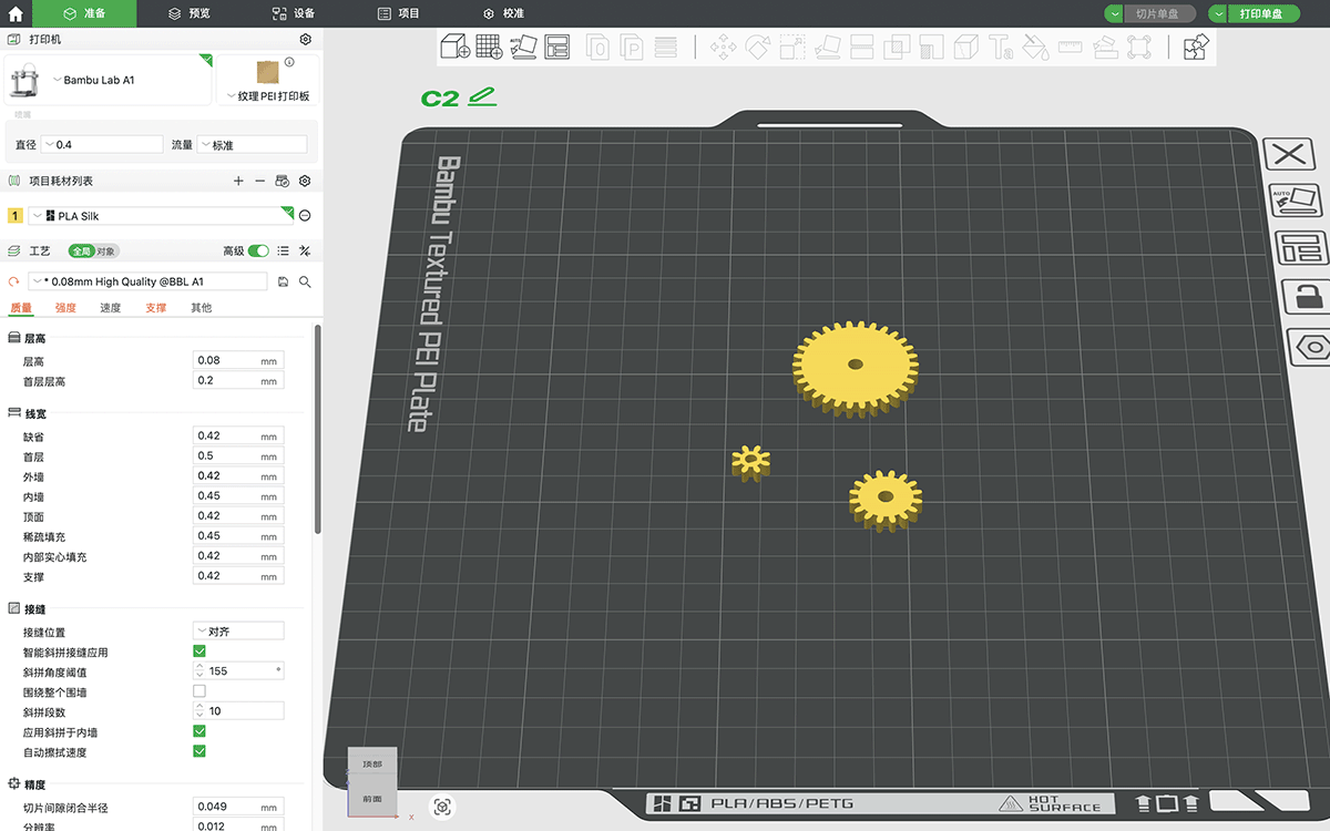
When printing gears, recommend selecting highest quality
Lantern Rotating Cage Cover Sticker Design
For the lantern rotating cage covers, I used light blue translucent PETG material for printing, with 1mm thickness. Single piece dimensions are 48×151 mm, with a total of 6 pieces. I wanted to use vinyl cutting for some Chinese-style paper-cut patterns to stick on the lantern cover surface.
So I tried using the online tool https://www.lovart.ai/, through prompts and Chinese paper-cut reference images, I made requests. After several rounds of communication, I got the Journey to the West paper-cut style patterns I needed.
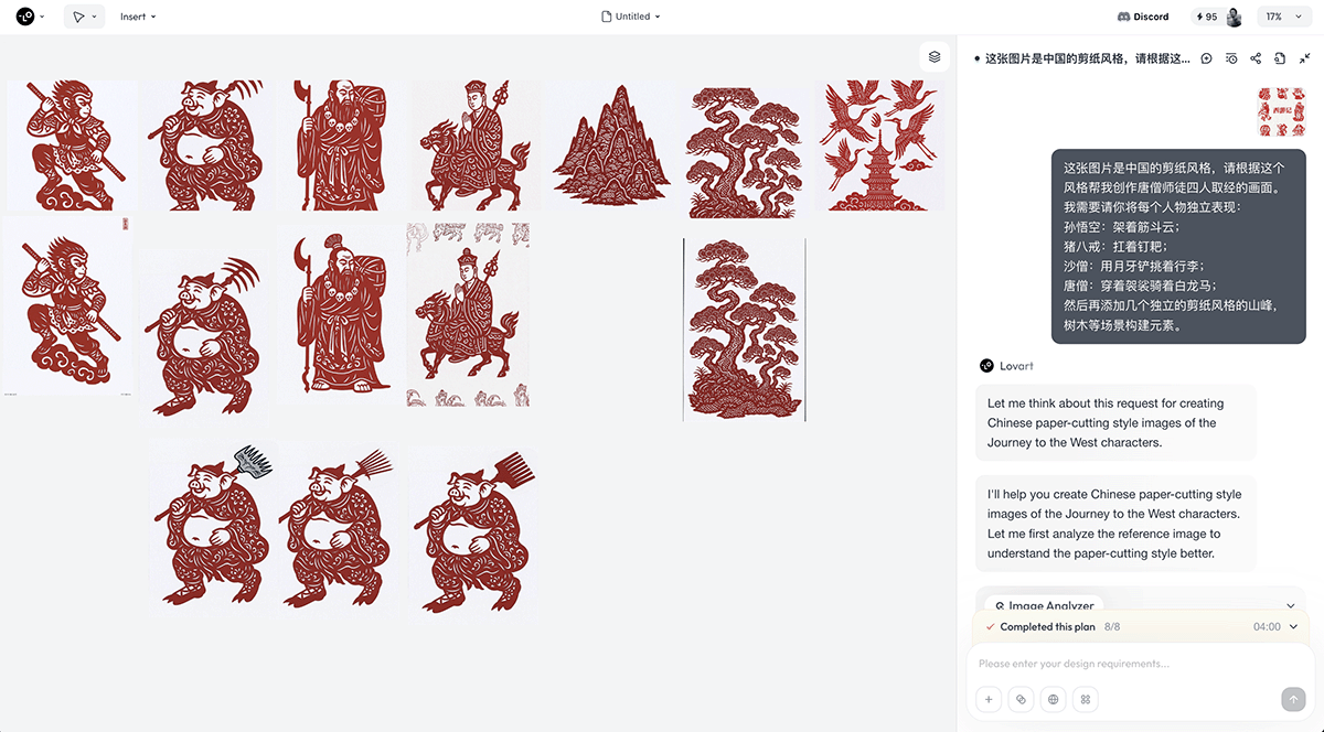
The online tool https://www.lovart.ai/ can generate series of high-quality Journey to the West paper-cut illustrations through the paper-cut reference images I provided and prompts
Then I planned the required patterns according to the dimensions of the 6 rotating cage lantern covers, as shown in the figure below.
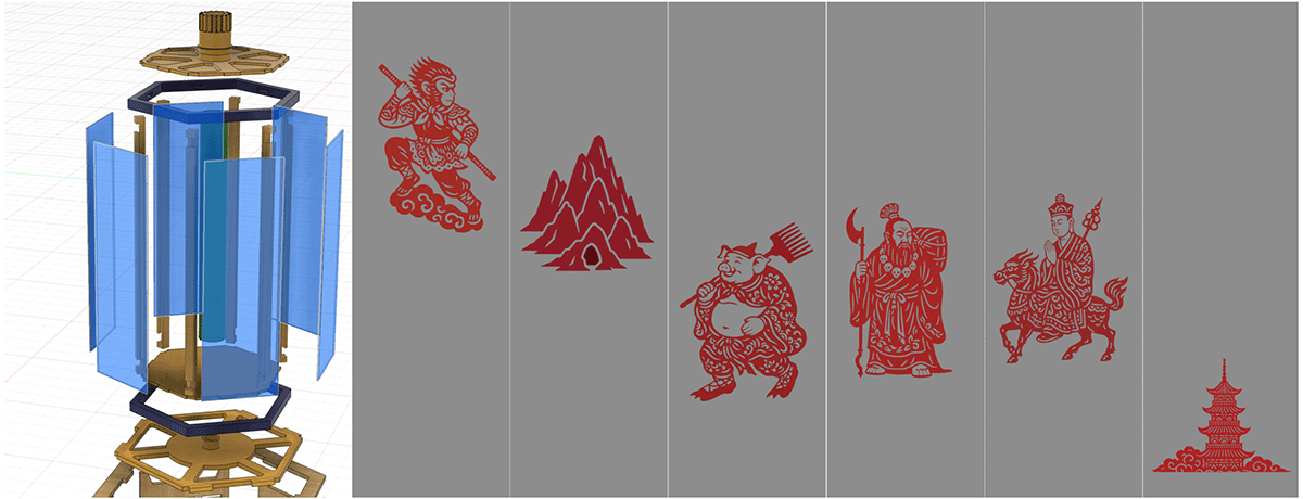
Readjusted the size of AI-generated paper-cut patterns to fit the size of rotating cage cover panels
Obtained the patterns needed for the vinyl cutting machine, as shown in the figure below.

Patterns needed for vinyl cutting machine
Electronic Hardware Design
The PCB of the Magical Revolving Lantern went through 4 major iterations.
Version 1: Weekly Course Electronic Project Verification
In my Fab Academy course weekly projects, I designed an initial version PCB with KiCad and tried both CNC cutting and commercial manufacturing (JLC production). These 2 boards from the first generation helped me complete various electronic projects in the first 15 weeks, verifying various electronic functions required for the lantern.
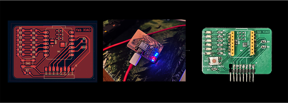
Generation 1 PCB designed for Magical Revolving Lantern. To facilitate light effect testing, I placed the LED array diameter on the PCB and tried both CNC milling and commercial manufacturing
Version 2: Milled Semicircular PCB
The entire PCB of the Magical Revolving Lantern began to be planned as circular to fit exactly on top of the gear compartment, but this left insufficient space for the battery, so according to the structure, I adopted a semicircular ring PCB integrated design to make room for the battery.
From Version 2, I started trying EasyEDA, feeling that its library is much richer and convenient for manufacturing. I first designed a milled PCB aiming for basic functional verification, but found that wiring was troublesome.
Version 2 PCB schematic
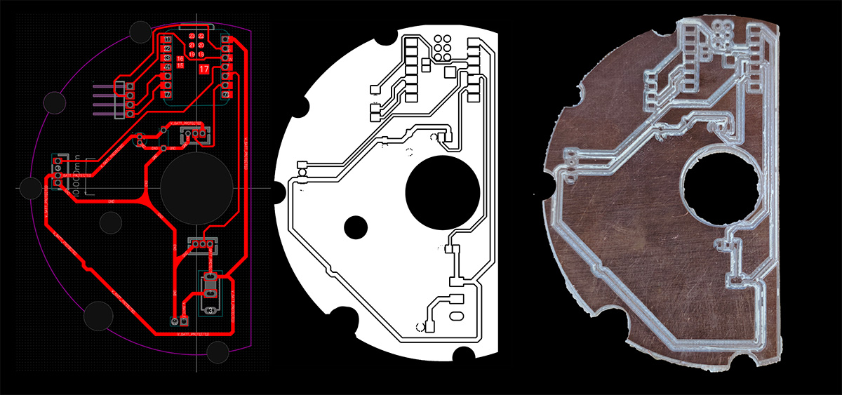
Version 2: Left is the milled PCB design from EasyEDA, middle is PNG converted from nc file for circuit cutting output by CNC, right is the milled PCB
Testing the size of the milled PCB, it fits well with the PCB compartment.
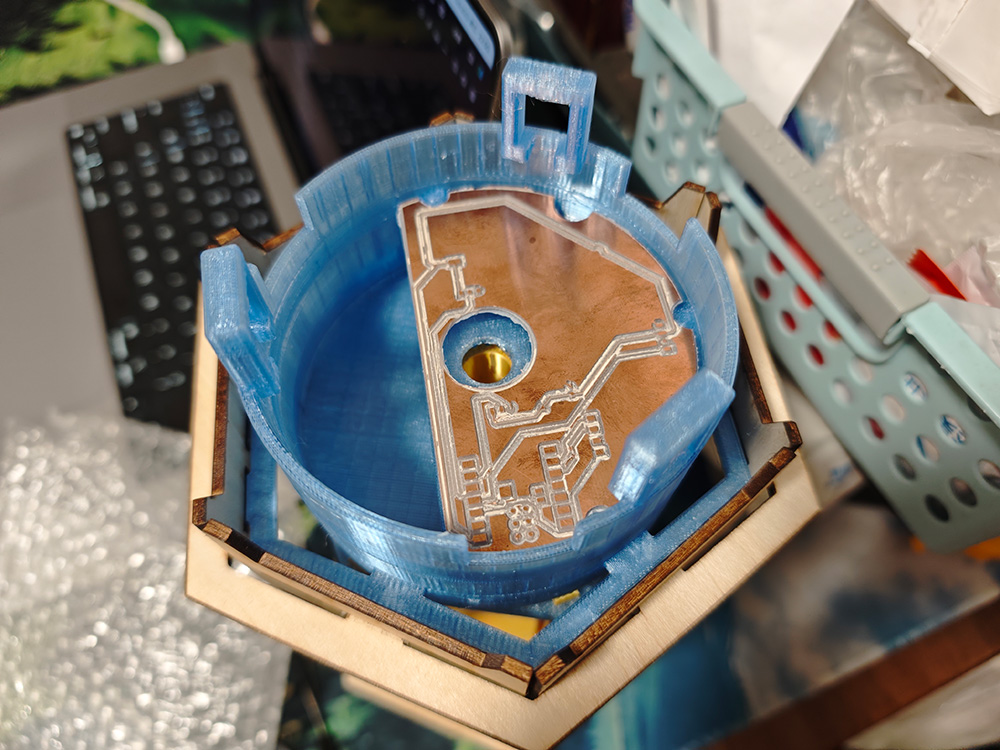
Testing Version 2 milled PCB dimensions
I used this PCB to initially verify XIAO ESP32 C3, battery, switch, motor, LED strips and gesture sensors, but the main problem was that wiring was complex and not very stable.
Version 3: Double-sided PCB Attempt - Various Failure Lessons
Version 2 attempted more complex PCB design (I wrote this process into Week 17 individual assignment), including double-sided and adding wire-to-board connector support. Because the board was quite complex, I had it manufactured through JLC. The board came out beautifully, and I confidently soldered all components.
The soldered board looked great, but reality was that this version's new design had many bugs, causing this board to be completely scrapped. Main problems included:
- Incorrect spacing of XIAO dual-row pin sockets (about 3mm too wide), preventing XIAO from fitting into sockets;
- Reversed wire order for LED strips, gesture sensors and motor connector interfaces, causing all wire orders to be reversed when plugged in;
- AI-suggested Schottky diodes cause voltage drop, preventing battery power supply to XIAO;
I addressed these issues and modified the PCB design a third time.
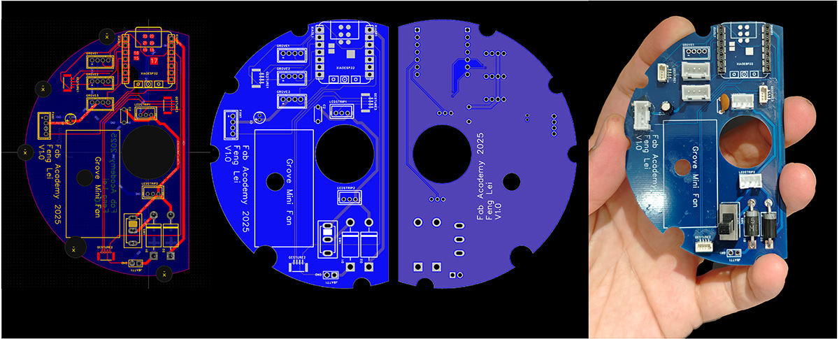
Version 4: Double-sided PCB Revision Attempt - Finally Successful
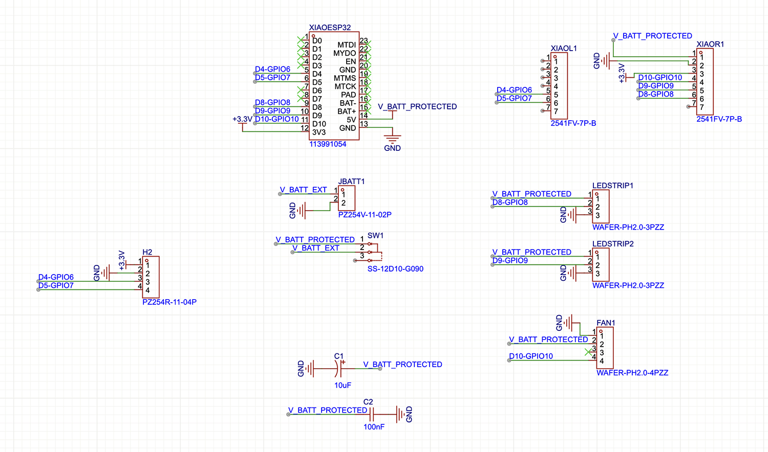
Addressing the problems encountered in actual soldering and testing of the PCB designed and manufactured in Week 17, I made a round of improvements. The final completed circuit schematic is shown below.
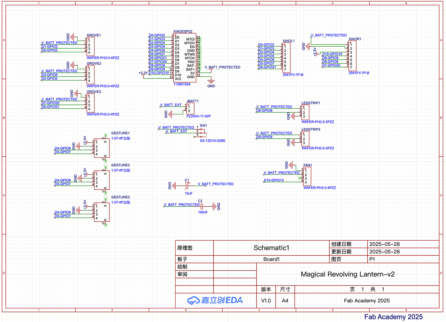
Version 4 PCB design circuit schematic
In EasyEDA, I readjusted components and wiring according to the schematic and remanufactured it. This time the component soldering and testing went very smoothly.
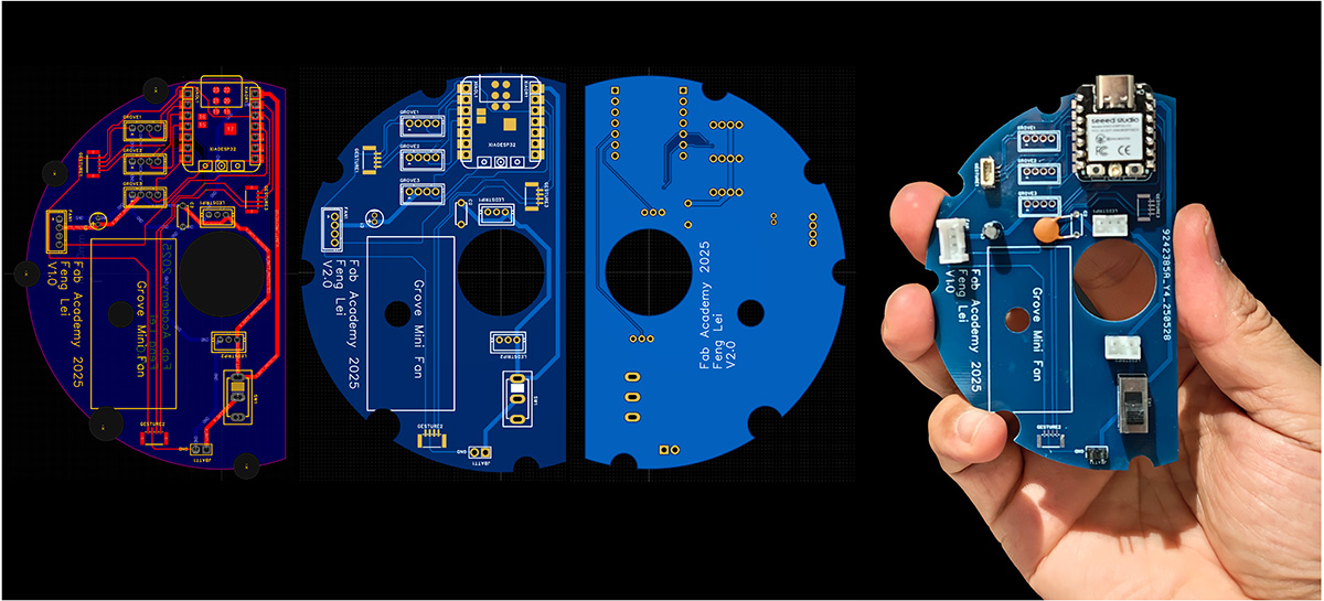
Using EasyEDA for routing and displaying 3D effects
The final module connection diagram is shown below:
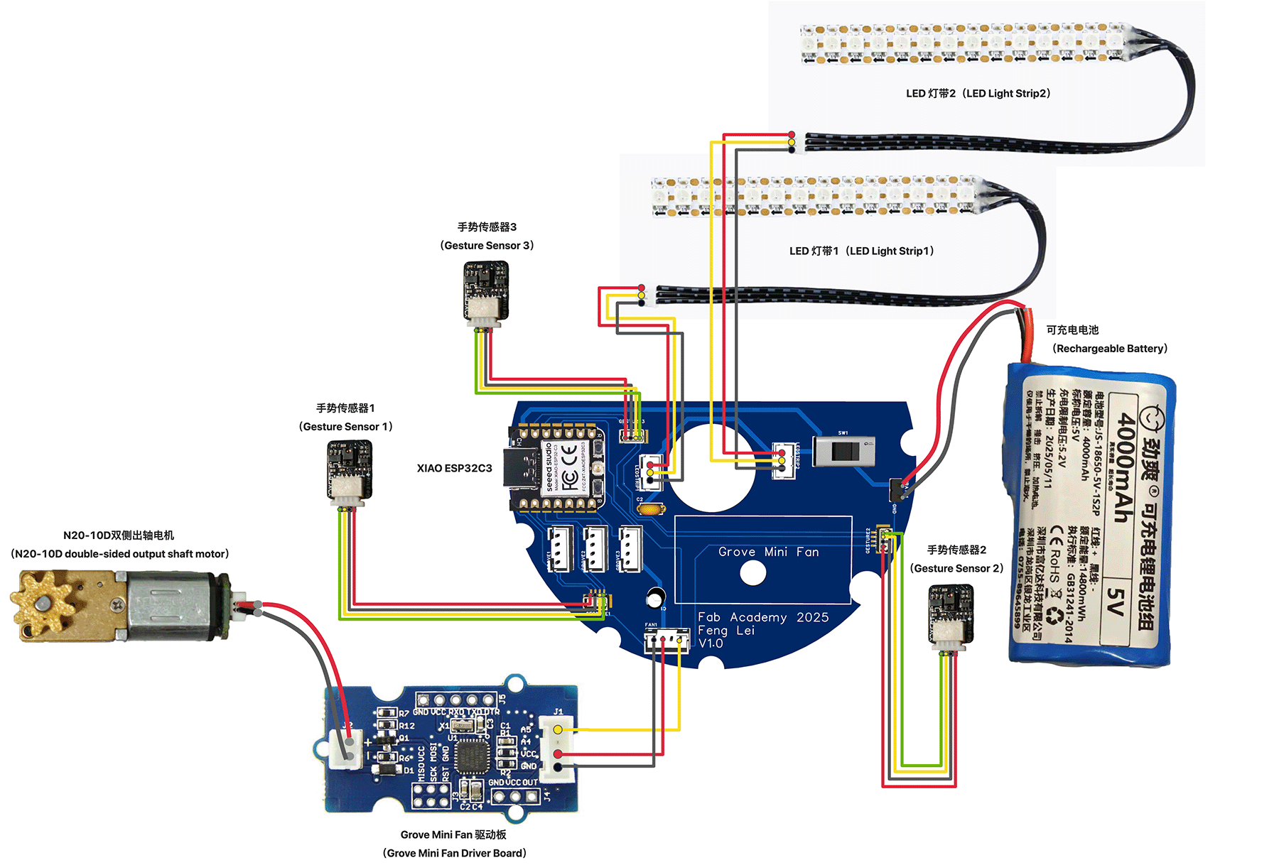
Electronic hardware connection diagram used by the lantern
Control Core: XIAO ESP32C3 I chose this little guy for three reasons: compact size, built-in WiFi, Arduino compatibility. On a coin-sized PCB, it serves as the brain of the entire system.
Sensing System: Three-Eye Detective Three APDS-9960 sensors distributed at 120°, theoretically covering all directions on the horizontal plane. Each sensor can not only recognize gestures but also detect distance and ambient light intensity, leaving expansion space for future intelligence.
Actuator: Gear Transmission + LED Array The mechanical part uses a precisely calculated gear system with optimized transmission ratio, ensuring sufficient torque while controlling speed within reasonable range. The LED part consists of 2 light strips (each strip has 14 RGB LEDs), creating rich light and shadow effects.
Testing Version 4 PCB to ensure all connected devices work properly.
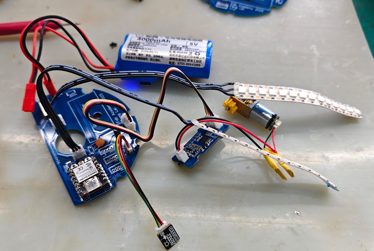
Version 4 PCB testing successful
Assembly Process
With structural components and PCB ready, we can proceed with assembly. Below are all the parts and components of a Magical Revolving Lantern.
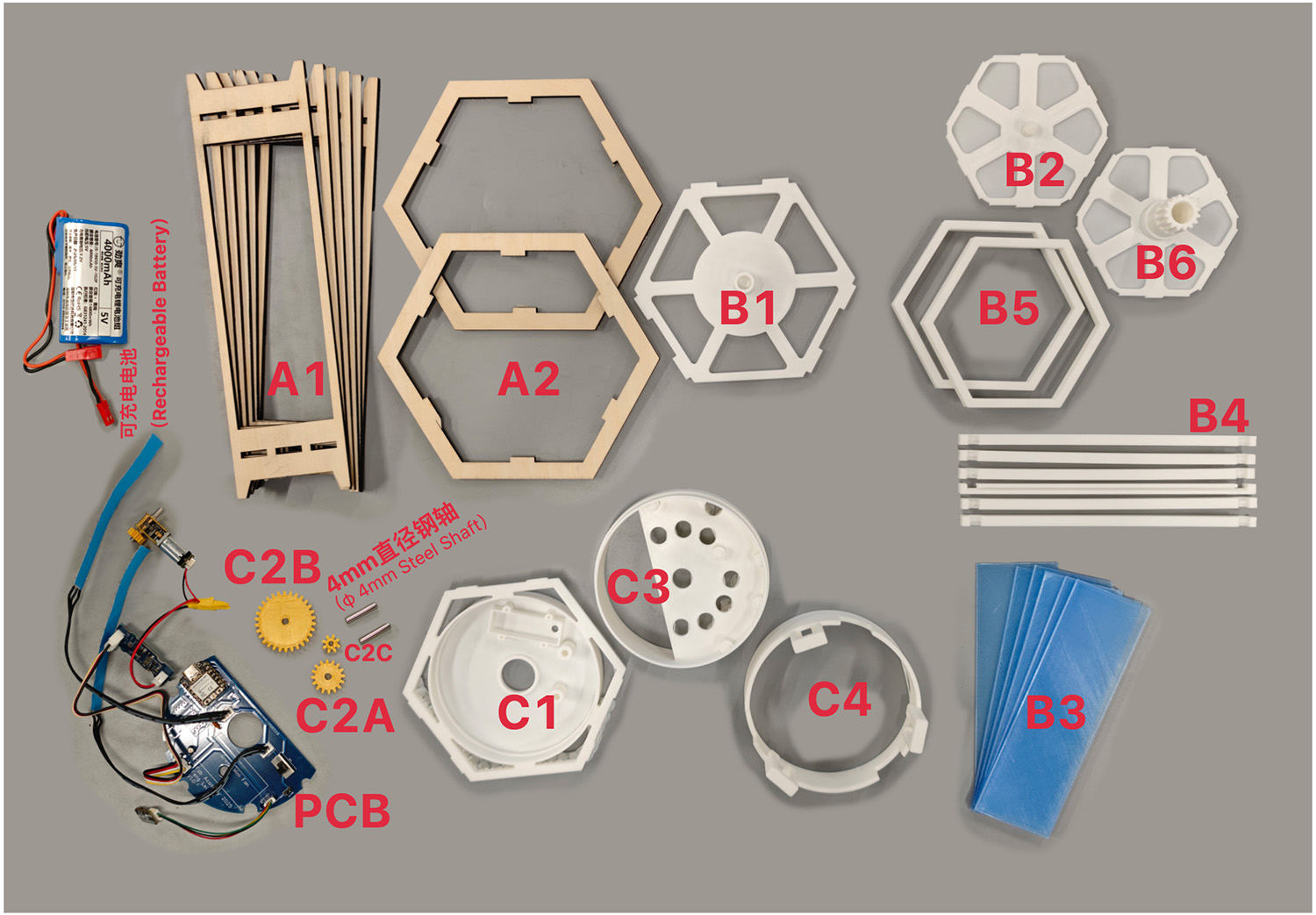
All parts and components of the Magical Revolving Lantern
Assembling Outer Frame Structure A1, A2 and B1
When assembling A1 and A2, you can use a hot glue gun for initial fixing (small amount only, to prevent A1 from falling during inversion). Once assembly is complete, the entire structure becomes very tight and solid. Note that B1 has a cylindrical protrusion that must face upward.
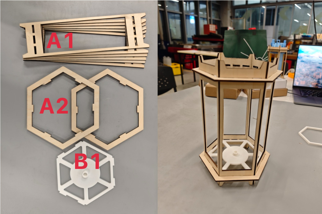
First assemble laser-cut wooden boards A1 and A2, then embed B1 into bottom slots, noting that B1's cylindrical groove should face upward
Assembling Lantern Rotating Cage
This step requires patience. Note that B2 needs the conical rotating shaft face downward so the bottom conical shaft of the rotating cage can be placed into B1's cylindrical groove. The assembled rotating cage is shown below. You can try placing the assembled rotating cage into the outer frame assembled in step 1, ensuring the bottom cone of the rotating cage fits into the lower base's cylindrical groove, allowing easy hand rotation of the rotating cage.
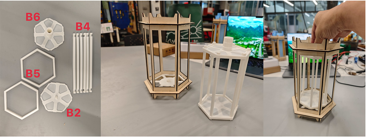
Assemble B2, B4, B5 and B6 to get a solid rotating cage, can be placed into the outer frame assembled in step 1 for testing
Adding Cover Panels and Placing LED Light Strips to Rotating Cage
Carefully embed the rotating cage cover panels (B3) into the grooves on the sides of the rotating cage support columns. When 2 panels remain, remember to thread the thinner plug end of the LED strips from inside through the shaft hole of B6 at the top of the rotating cage, then seal the last two cover panels.
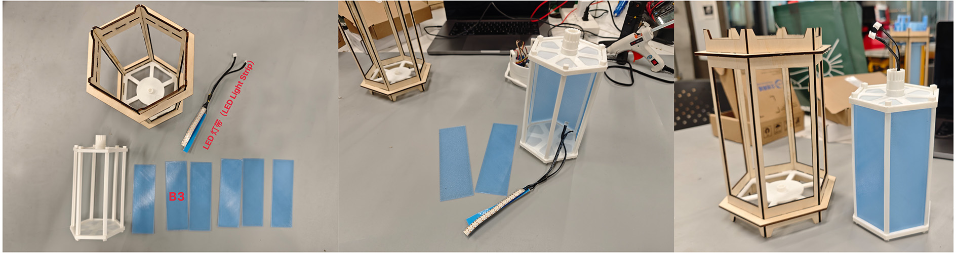
Install lantern cover panels (B3), remember when 2 panels remain, thread the LED strip connectors through the shaft hole of B6 at the top of the rotating cage, then install the remaining 2 panels to seal the lantern
Assembling Gear Compartment (C1) and C2A & C2B Gears
Insert 4mm diameter steel shafts into the 2 shaft holes of B3, and place C2A and C2B gears respectively, then place B3 into the revolving lantern structure, let the rotating cage's geared shaft pass through B3's center hole. Push B3 down into the wooden lantern frame's slots, and the rotating cage truly becomes stable. At this point, you can manually rotate the rotating cage's central shaft gear, and you should see the rotating cage rotate very flexibly while driving C2A and C2B gears to rotate.
Insert 4mm diameter steel shafts into the 2 shaft seats of gear compartment (C1), then place gear C2B (the largest one, positioned close to the rotating cage central shaft gear) and C2A on the steel shafts. Push C1 down along the wooden frame, letting the rotating cage's geared central shaft pass through C1's center hole, then get caught by the wooden side rail slots
Integrating PCB Compartment and Top Cover
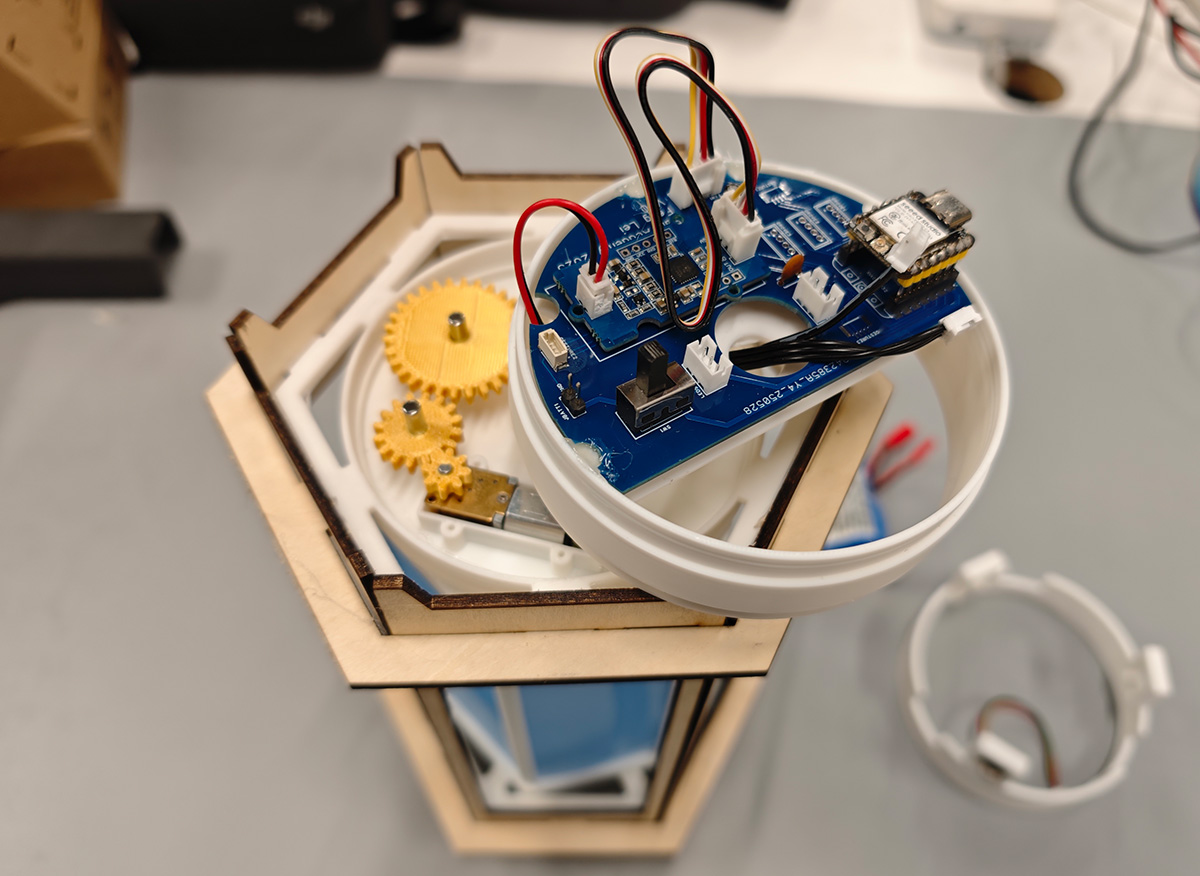
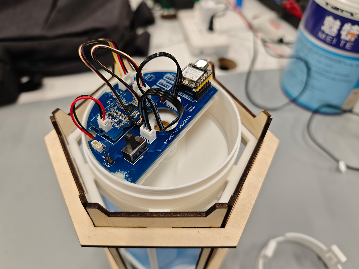
First place the PCB along the positioning holes in the PCB compartment (C3), can use hot glue gun to fix the PCB, then also fix the Grove Mini FAN control board on the PCB, and connect the PCB and control board with Grove wire. The 2P motor wire from one end of the control board can pass through the hole on the side of the PCB, connecting to the motor. Then fix the head of 1 gesture sensor on the bracket reserved in C4 with hot glue gun, noting that the sensor probe faces outward.
Place the PCB board in PCB compartment (C3), connect the motor control board, the 2P motor wire from one end of the control board can pass through the hole on the side of the PCB; fix the head of 1 gesture sensor on the bracket reserved in C4 with hot glue gun
Install C2C gear on the motor shaft and place in the battery compartment.
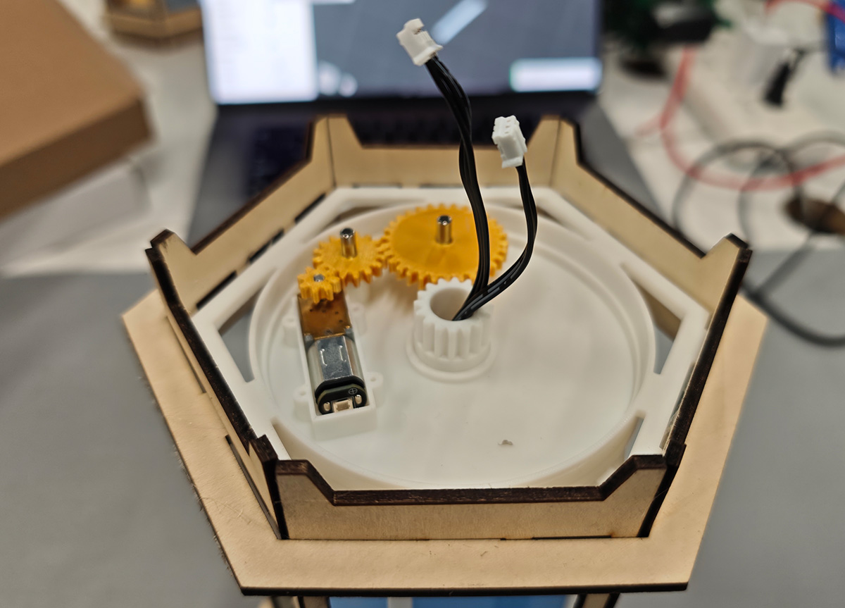
First place the motor in the battery compartment
Before installing the PCB compartment, remember to connect the motor's 2P power wire.
Connect the motor 2P wire first, then install the PCB compartment
Carefully insert the PCB compartment on top of the gear compartment, then connect the 2 LED strip connectors.
Install PCB compartment and plug in LED strip connectors
Insert the battery and connect the battery to the PCB socket, being careful not to reverse the red and black wires.
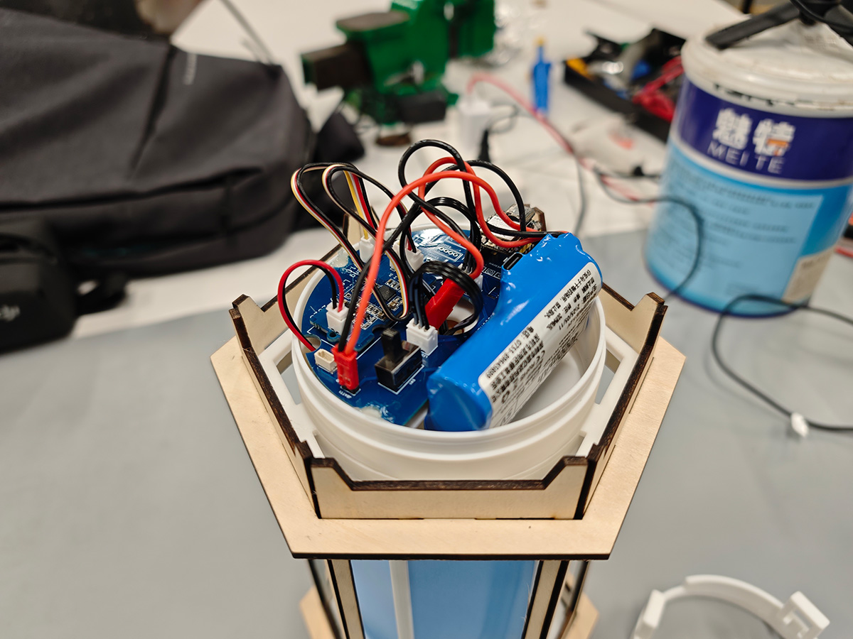
Connect battery
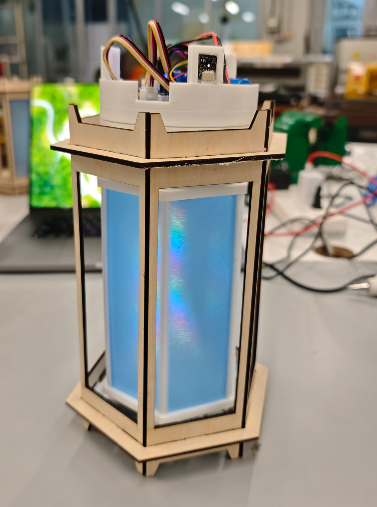
Finally, connect the gesture sensor connector to the PCB socket, then plug in the top cover, turn on the switch, now the motor, light strips and gesture sensors all work.
Vinyl Sticker Cutting and Installation
The printed stickers, with my wife's help, completed the transfer of 1 pattern. The finally cut stickers were applied to the rotating cage cover panels.
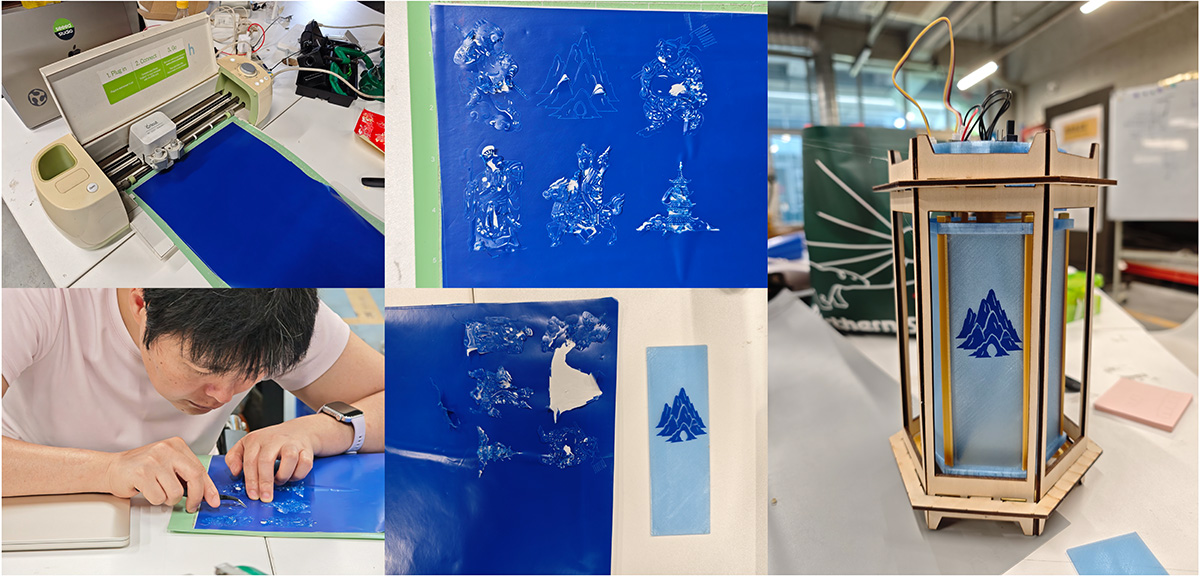
Used vinyl cutting machine to cut paper-cut style stickers, then with wife's help transferred them to the rotating cage cover panels
Interaction Design
This part has been verified and tested in previous courses. Control of the revolving lantern is through 3 methods:
- Lantern gesture sensors
- Web control via Wi-Fi
- Multiple lanterns can automatically synchronize via Wi-Fi/MQTT
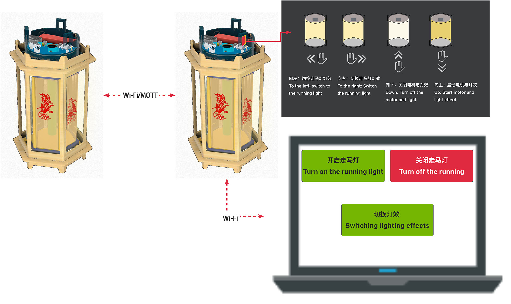
Lantern can be controlled in 3 ways
Gesture Sensor Control
I integrated ultra-mini APDS-9960 gesture sensors, related programs have been verified in Week 9 assignment. Here I adjusted the gesture control functions:
- Left/Right gestures: Switch between multiple lighting effect modes (traditional revolving lantern, flame effect, rainbow rotation, breathing sync, meteor chase, festival celebration)
- Up gesture: Turn on revolving lantern (simultaneously start motor and lighting effects)
- Down gesture: Turn off revolving lantern (stop motor and lighting effects)
Web Control via Wi-Fi
Related programs have been verified in Week 15 individual assignment. For Web control in the Final Project, I plan to place 3 buttons:
- Switch lighting effects
- Turn on revolving lantern
- Turn off revolving lantern
Multiple Lanterns Can Automatically Synchronize via Wi-Fi/MQTT
Related programs have been verified in Week 11 individual assignment. Multiple lanterns will automatically synchronize via Wi-Fi using MQTT protocol.
Software Architecture
The software part adopts a multi-task concurrent architecture design, fully utilizing the dual-core advantages of ESP32C3.
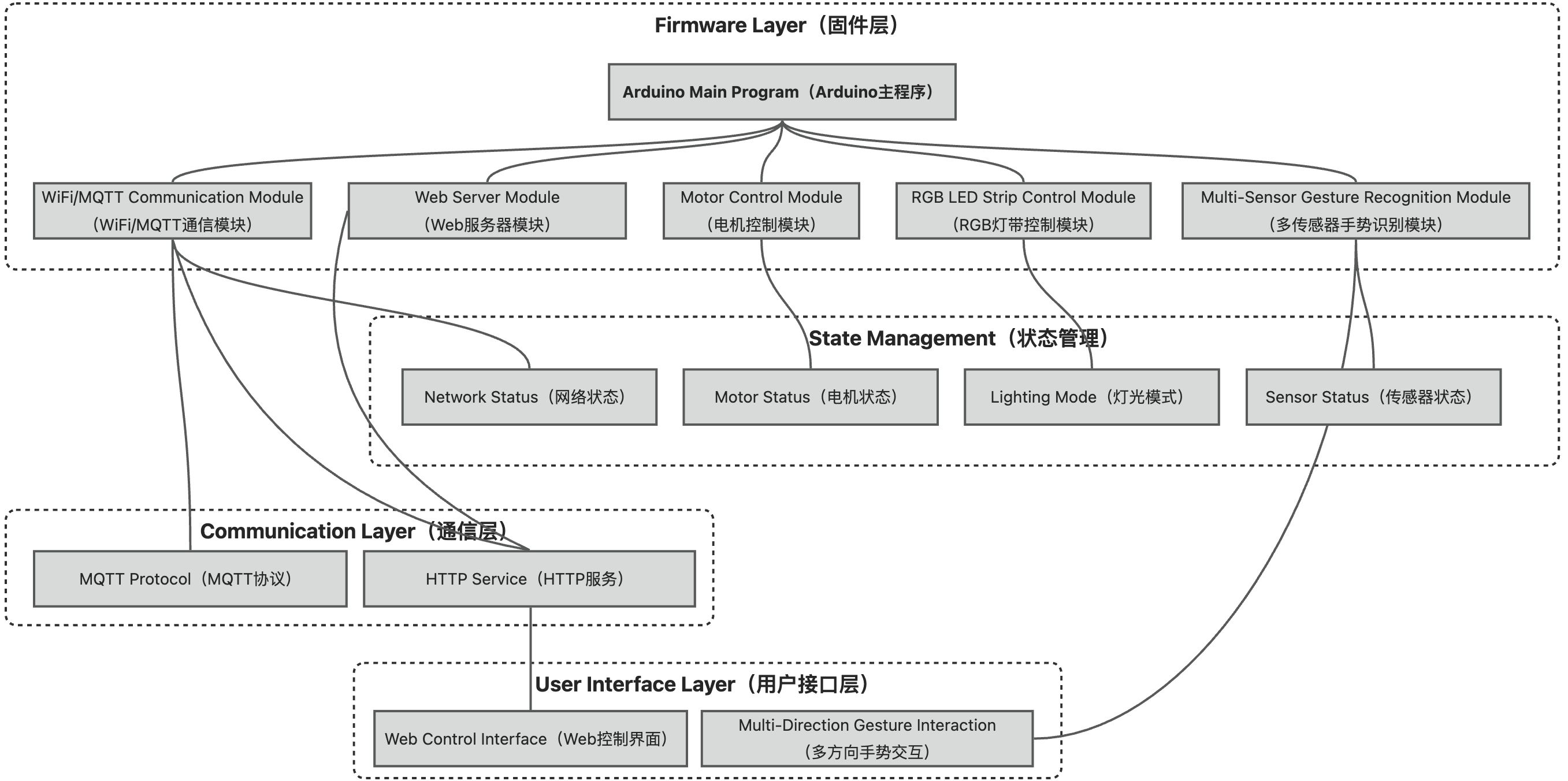
Software Architecture: Multi-task concurrent processing diagram
Gesture Recognition Algorithm: Not simple direction judgment, but composite gesture recognition based on timing analysis. For example, "circle drawing" gesture triggers rainbow mode, "upward push" gesture gradually increases brightness.
LED Control Strategy: Implements smooth color transition algorithms, avoiding abrupt jumps. Also supports multiple preset modes: breathing light, flowing light, strobe, gradient, etc.
Communication Protocol Design: Combines WiFi and ESP-NOW communication methods. Daily control uses WiFi (stable, long distance), group synchronization uses ESP-NOW (low latency, no router needed).
Staged Testing Programs
Special Note: All programs in this project were written by Claude Sonnet 4. The AI generated the code based on other relevant course assignment documents and requirements I provided, which were then tested and improved upon.
Motor Switch Test Program
Initially only connecting the motor and testing if the motor can work normally, test program as follows:
#define MOTOR_PIN 10

void setup() {
  Serial.begin(115200);
  delay(2000);
  Serial.println("Basic Motor Test - ON/OFF only");

  pinMode(MOTOR_PIN, OUTPUT);
  digitalWrite(MOTOR_PIN, LOW);
}

void loop() {
  Serial.println("Motor ON");
  digitalWrite(MOTOR_PIN, HIGH);
  delay(3000);

  Serial.println("Motor OFF");
  digitalWrite(MOTOR_PIN, LOW);
  delay(3000);
}LED Light Effect Test
Then only connecting 1 LED light (GPIO9), testing light effect control program as follows:
#include <Adafruit_NeoPixel.h>
#define PIN 9    // Changed to GPIO 9
#define MAX_LED 14

Adafruit_NeoPixel strip = Adafruit_NeoPixel(MAX_LED, PIN, NEO_GRB + NEO_KHZ800);

void setup() {
  Serial.begin(115200);
  delay(2000);

  Serial.println("Testing GPIO 9...");

  strip.begin();
  strip.setBrightness(20);

  // Stable initialization
  strip.clear();
  strip.show();
  delay(100);
  strip.clear();
  strip.show();
  delay(100);
}

void loop() {
  // Simple red green blue test
  Serial.println("RED");
  for(int i = 0; i < MAX_LED; i++) {
    strip.setPixelColor(i, strip.Color(50, 0, 0));
  }
  strip.show();
  delay(1000);

  Serial.println("GREEN");
  for(int i = 0; i < MAX_LED; i++) {
    strip.setPixelColor(i, strip.Color(0, 50, 0));
  }
  strip.show();
  delay(1000);

  Serial.println("BLUE");
  for(int i = 0; i < MAX_LED; i++) {
    strip.setPixelColor(i, strip.Color(0, 0, 50));
  }
  strip.show();
  delay(1000);

  Serial.println("OFF");
  strip.clear();
  strip.show();
  delay(1000);
}LED Light Effects and Motor Program
After multiple debugging and revisions, completed the test program for motor and 2 LEDs working synchronously:
#include <Adafruit_NeoPixel.h>

// Hardware definitions
#define LED_PIN_1 9      // GPIO9 controls first LED strip
#define LED_PIN_2 8      // GPIO8 controls second LED strip
#define MOTOR_PIN 10     // GPIO10 controls motor
#define MAX_LED 14       // 14 LEDs

// Dual LED strip initialization
Adafruit_NeoPixel strip1 = Adafruit_NeoPixel(MAX_LED, LED_PIN_1, NEO_GRB + NEO_KHZ800);
Adafruit_NeoPixel strip2 = Adafruit_NeoPixel(MAX_LED, LED_PIN_2, NEO_GRB + NEO_KHZ800);

// PWM parameters
const int PWM_FREQ = 5000;
const int PWM_RESOLUTION = 8;

// Color definitions (low brightness)
#define RED    strip1.Color(50, 0, 0)
#define GREEN  strip1.Color(0, 50, 0)
#define BLUE   strip1.Color(0, 0, 50)
#define YELLOW strip1.Color(50, 50, 0)
#define PURPLE strip1.Color(50, 0, 50)
#define CYAN   strip1.Color(0, 50, 50)
#define WHITE  strip1.Color(30, 30, 30)
#define ORANGE strip1.Color(60, 20, 0)
#define OFF    strip1.Color(0, 0, 0)

// Current mode
int currentMode = 0;
const int TOTAL_MODES = 6;

// Helper function: Set both LED strips' pixel colors simultaneously
void setDualPixelColor(int pixel, uint32_t color) {
  strip1.setPixelColor(pixel, color);
  strip2.setPixelColor(pixel, color);
}

// Helper function: Display both LED strips simultaneously
void showDualStrips() {
  strip1.show();
  strip2.show();
}

// Helper function: Clear both LED strips simultaneously
void clearDualStrips() {
  strip1.clear();
  strip2.clear();
}

// Helper function: Create color (compatible with both strips)
uint32_t createColor(int r, int g, int b) {
  return strip1.Color(r, g, b);
}

void setup() {
  Serial.begin(115200);
  delay(2000);

  Serial.println("=== Magical Revolving Lantern Dual LED Version Startup ===");
  Serial.println("Smart Lantern - Dual LED & Motor Integration");

  // Initialize both LED strips
  strip1.begin();
  strip1.setBrightness(20);
  strip1.clear();
  strip1.show();

  strip2.begin();
  strip2.setBrightness(20);
  strip2.clear();
  strip2.show();

  delay(100);

  clearDualStrips();
  showDualStrips();

  // Initialize motor PWM
  ledcAttach(MOTOR_PIN, PWM_FREQ, PWM_RESOLUTION);
  ledcWrite(MOTOR_PIN, 0);

  // Startup animation
  startupSequence();

  Serial.println("\nDual LED system ready! Starting effect operations...\n");
}

void loop() {
  switch(currentMode) {
    case 0:
      Serial.println("Mode 1: Traditional Lantern (Dual LED)");
      traditionalLanternMode();
      break;

    case 1:
      Serial.println("Mode 2: Fire Effect (Dual LED)");
      fireMode();
      break;

    case 2:
      Serial.println("Mode 3: Rainbow Spin (Dual LED)");
      rainbowSpinMode();
      break;

    case 3:
      Serial.println("Mode 4: Breathing Sync (Dual LED)");
      breathingSyncMode();
      break;

    case 4:
      Serial.println("Mode 5: Meteor Chase (Dual LED)");
      meteorChaseMode();
      break;

    case 5:
      Serial.println("Mode 6: Festival Mode (Dual LED)");
      festivalMode();
      break;
  }

  // Switch to next mode
  currentMode = (currentMode + 1) % TOTAL_MODES;

  // Inter-mode transition
  transitionEffect();
}

// Startup animation
void startupSequence() {
  Serial.println("Startup sequence - Dual LED sync...");

  // Motor slow startup
  for(int speed = 0; speed <= 100; speed += 5) {
    ledcWrite(MOTOR_PIN, speed);
    delay(30);
  }

  // Both LED strips light up one by one synchronously
  for(int i = 0; i < MAX_LED; i++) {
    setDualPixelColor(i, WHITE);
    showDualStrips();
    delay(50);
  }

  delay(500);

  // Turn off all
  clearDualStrips();
  showDualStrips();
  ledcWrite(MOTOR_PIN, 0);
  delay(500);
}

// Mode 1: Traditional lantern effect
void traditionalLanternMode() {
  uint32_t colors[] = {RED, ORANGE, YELLOW, GREEN, CYAN, BLUE};
  int numColors = 6;

  // Motor medium speed rotation
  ledcWrite(MOTOR_PIN, 120);

  // Run for 30 seconds
  unsigned long startTime = millis();
  int offset = 0;

  while(millis() - startTime < 30000) {
    // Dual LED color flow
    for(int i = 0; i < MAX_LED; i++) {
      int colorIndex = (i + offset) % numColors;
      setDualPixelColor(i, colors[colorIndex]);
    }
    showDualStrips();

    offset++;
    delay(200);  // Match motor speed
  }

  // Gradually stop
  for(int speed = 120; speed >= 0; speed -= 5) {
    ledcWrite(MOTOR_PIN, speed);
    delay(50);
  }
}

// Mode 2: Fire effect
void fireMode() {
  // Motor slow rotation, simulating flame flickering
  ledcWrite(MOTOR_PIN, 80);

  unsigned long startTime = millis();

  while(millis() - startTime < 30000) {
    // Flame flicker effect
    for(int i = 0; i < MAX_LED; i++) {
      int flicker = random(20, 80);
      int r = flicker;
      int g = flicker * 0.3;
      int b = 0;
      setDualPixelColor(i, createColor(r, g, b));
    }
    showDualStrips();

    // Motor speed random variation
    int motorSpeed = 60 + random(-20, 20);
    ledcWrite(MOTOR_PIN, motorSpeed);

    delay(50);
  }

  ledcWrite(MOTOR_PIN, 0);
}

// Mode 3: Rainbow spin
void rainbowSpinMode() {
  unsigned long startTime = millis();
  int colorOffset = 0;

  int loopCount = 0;

  while(millis() - startTime < 30000) {
    // Dual LED rainbow display - using simple RGB cycle
    for(int i = 0; i < MAX_LED; i++) {
      // Create rainbow effect
      int phase = ((i * 255 / MAX_LED) + (colorOffset * 10)) % 255;
      int r = 0, g = 0, b = 0;

      if(phase < 85) {
        // Red to green
        r = (255 - phase * 3) / 5;  // Directly divide by 5 to reduce brightness
        g = (phase * 3) / 5;
        b = 0;
      } else if(phase < 170) {
        // Green to blue
        phase -= 85;
        r = 0;
        g = (255 - phase * 3) / 5;
        b = (phase * 3) / 5;
      } else {
        // Blue to red
        phase -= 170;
        r = (phase * 3) / 5;
        g = 0;
        b = (255 - phase * 3) / 5;
      }

      setDualPixelColor(i, createColor(r, g, b));
    }
    showDualStrips();

    // Motor speed varies with rainbow
    int motorSpeed = 120;  // Fixed speed
    ledcWrite(MOTOR_PIN, motorSpeed);

    colorOffset = (colorOffset + 1) % 26;  // Cycle range
    delay(100);  // Delay

    // Debug output
    loopCount++;
    if(loopCount % 10 == 0) {
      Serial.print(".");
    }
  }

  ledcWrite(MOTOR_PIN, 0);
}

// Mode 4: Breathing sync
void breathingSyncMode() {
  unsigned long startTime = millis();

  while(millis() - startTime < 30000) {
    // Breathing cycle
    // Brighten + accelerate
    for(int level = 0; level <= 100; level += 2) {
      // Dual LED brightness
      int brightness = level / 2;
      for(int i = 0; i < MAX_LED; i++) {
        setDualPixelColor(i, createColor(brightness, brightness/2, 0));
      }
      showDualStrips();

      // Motor speed
      ledcWrite(MOTOR_PIN, 50 + level);
      delay(30);
    }

    // Dim + decelerate
    for(int level = 100; level >= 0; level -= 2) {
      // Dual LED brightness
      int brightness = level / 2;
      for(int i = 0; i < MAX_LED; i++) {
        setDualPixelColor(i, createColor(brightness, brightness/2, 0));
      }
      showDualStrips();

      // Motor speed
      ledcWrite(MOTOR_PIN, 50 + level);
      delay(30);
    }
  }

  ledcWrite(MOTOR_PIN, 0);
}

// Mode 5: Meteor chase
void meteorChaseMode() {
  // Motor fast rotation
  ledcWrite(MOTOR_PIN, 180);

  unsigned long startTime = millis();
  int position = 0;

  while(millis() - startTime < 30000) {
    clearDualStrips();

    // Main meteor
    setDualPixelColor(position, WHITE);

    // Trail
    if(position > 0) {
      setDualPixelColor((position - 1) % MAX_LED, createColor(20, 20, 20));
    }
    if(position > 1) {
      setDualPixelColor((position - 2) % MAX_LED, createColor(10, 10, 10));
    }
    if(position > 2) {
      setDualPixelColor((position - 3) % MAX_LED, createColor(5, 5, 5));
    }

    showDualStrips();

    position = (position + 1) % MAX_LED;
    delay(50);
  }

  // Decelerate stop
  for(int speed = 180; speed >= 0; speed -= 5) {
    ledcWrite(MOTOR_PIN, speed);
    delay(30);
  }
}

// Mode 6: Festival celebration
void festivalMode() {
  uint32_t festiveColors[] = {RED, GREEN, YELLOW, BLUE, PURPLE};

  // Motor medium speed rotation
  ledcWrite(MOTOR_PIN, 130);

  unsigned long startTime = millis();

  while(millis() - startTime < 30000) {
    // Random flashing
    for(int i = 0; i < MAX_LED; i++) {
      if(random(10) > 7) {  // 30% chance to flash
        setDualPixelColor(i, festiveColors[random(5)]);
      } else {
        setDualPixelColor(i, OFF);
      }
    }
    showDualStrips();

    // Occasional motor speed change
    if(random(100) > 90) {
      ledcWrite(MOTOR_PIN, 100 + random(60));
    }

    delay(100);
  }

  ledcWrite(MOTOR_PIN, 0);
}

// Inter-mode transition effect
void transitionEffect() {
  Serial.println("Mode switching - Dual LED sync...");

  // Stop motor
  ledcWrite(MOTOR_PIN, 0);

  // Gradually dim all LEDs
  for(int brightness = 20; brightness >= 0; brightness--) {
    for(int i = 0; i < MAX_LED; i++) {
      setDualPixelColor(i, createColor(brightness, brightness, brightness));
    }
    showDualStrips();
    delay(50);
  }

  clearDualStrips();
  showDualStrips();
  delay(1000);
}Adding Multi-Gesture Sensor Test Program
#include <Adafruit_NeoPixel.h>
#include <Wire.h>
#include "XLOT_APDS9960AD.h"

// Hardware definitions
#define LED_PIN_1 9      // GPIO9 controls first LED strip
#define LED_PIN_2 8      // GPIO8 controls second LED strip
#define MOTOR_PIN 10     // GPIO10 controls motor
#define MAX_LED 14       // 14 LEDs

// I2C pin definitions (for gesture sensors)
#define SDA_PIN 6        // GPIO6 (D4) - I2C data line
#define SCL_PIN 7        // GPIO7 (D5) - I2C clock line

// Dual LED strip initialization
Adafruit_NeoPixel strip1 = Adafruit_NeoPixel(MAX_LED, LED_PIN_1, NEO_GRB + NEO_KHZ800);
Adafruit_NeoPixel strip2 = Adafruit_NeoPixel(MAX_LED, LED_PIN_2, NEO_GRB + NEO_KHZ800);

// Gesture sensor initialization
XLOT_APDS9960AD apds;

// PWM parameters
const int PWM_FREQ = 5000;
const int PWM_RESOLUTION = 8;

// Color definitions (low brightness)
#define RED    strip1.Color(50, 0, 0)
#define GREEN  strip1.Color(0, 50, 0)
#define BLUE   strip1.Color(0, 0, 50)
#define YELLOW strip1.Color(50, 50, 0)
#define PURPLE strip1.Color(50, 0, 50)
#define CYAN   strip1.Color(0, 50, 50)
#define WHITE  strip1.Color(30, 30, 30)
#define ORANGE strip1.Color(60, 20, 0)
#define OFF    strip1.Color(0, 0, 0)

// System state control
bool lanternOn = false;          // Lantern on/off state
int currentMode = 0;             // Current light effect mode
const int TOTAL_MODES = 6;       // Total number of modes
int currentBrightness = 20;      // Current brightness

// Mode control variables
unsigned long modeStartTime = 0; // Mode start time
int modeOffset = 0;              // Mode internal offset

// Gesture control debounce
unsigned long lastGestureTime = 0;
const unsigned long GESTURE_DELAY = 800; // Gesture interval 800ms

// Mode name array (for debug output)
const char* modeNames[TOTAL_MODES] = {
  "Traditional Lantern",
  "Fire Effect",
  "Rainbow Spin",
  "Breathing Sync",
  "Meteor Chase",
  "Festival Mode"
};

// Helper function: Set both LED strips' pixel colors simultaneously
void setDualPixelColor(int pixel, uint32_t color) {
  strip1.setPixelColor(pixel, color);
  strip2.setPixelColor(pixel, color);
}

// Helper function: Display both LED strips simultaneously
void showDualStrips() {
  strip1.show();
  strip2.show();
}

// Helper function: Clear both LED strips simultaneously
void clearDualStrips() {
  strip1.clear();
  strip2.clear();
}

// Helper function: Create color (compatible with both strips)
uint32_t createColor(int r, int g, int b) {
  return strip1.Color(r, g, b);
}

// Gesture handling function
void handleGestures() {
  uint8_t gesture = apds.readGesture();

  if (gesture != 0) {
    // Gesture debounce processing
    if (millis() - lastGestureTime < GESTURE_DELAY) {
      return;
    }
    lastGestureTime = millis();

    switch (gesture) {
      case APDS9960_LEFT:
        Serial.println("🔄 Gesture: ← (Switch to previous mode)");
        switchMode(-1);
        break;

      case APDS9960_RIGHT:
        Serial.println("🔄 Gesture: → (Switch to next mode)");
        switchMode(1);
        break;

      case APDS9960_UP:
        Serial.println("🔆 Gesture: ↑ (Turn on lantern)");
        turnOnLantern();
        break;

      case APDS9960_DOWN:
        Serial.println("🔅 Gesture: ↓ (Turn off lantern)");
        turnOffLantern();
        break;
    }
  }
}

// Mode switching function
void switchMode(int direction) {
  // Can only switch modes when lantern is on
  if (!lanternOn) {
    Serial.println("   ⚠️ Lantern not on, please swipe up first to turn on");
    return;
  }

  // Calculate new mode
  currentMode += direction;
  if (currentMode < 0) {
    currentMode = TOTAL_MODES - 1;
  } else if (currentMode >= TOTAL_MODES) {
    currentMode = 0;
  }

  // Reset mode time and offset
  modeStartTime = millis();
  modeOffset = 0;

  Serial.print("   ✅ Switched to mode ");
  Serial.print(currentMode + 1);
  Serial.print(": ");
  Serial.println(modeNames[currentMode]);

  // Show mode switch indicator
  showModeIndicator();
}

// Turn on lantern
void turnOnLantern() {
  if (lanternOn) {
    Serial.println("   ℹ️ Lantern already on");
    return;
  }

  lanternOn = true;
  modeStartTime = millis();
  modeOffset = 0;

  Serial.println("   ✅ Lantern turned on");
  Serial.print("   🎨 Current mode: ");
  Serial.println(modeNames[currentMode]);

  // Show startup animation
  showStartupAnimation();
}

// Turn off lantern
void turnOffLantern() {
  if (!lanternOn) {
    Serial.println("   ℹ️ Lantern already off");
    return;
  }

  lanternOn = false;

  Serial.println("   ✅ Lantern turned off");

  // Show shutdown animation
  showShutdownAnimation();

  // Stop motor and clear LEDs
  ledcWrite(MOTOR_PIN, 0);
  clearDualStrips();
  showDualStrips();
}

// Show mode switch indicator
void showModeIndicator() {
  clearDualStrips();

  // Show different colors based on mode
  uint32_t indicatorColor;
  switch(currentMode) {
    case 0: indicatorColor = ORANGE; break;  // Traditional lantern - orange
    case 1: indicatorColor = RED; break;     // Fire effect - red
    case 2: indicatorColor = createColor(25, 25, 25); break; // Rainbow spin - white
    case 3: indicatorColor = YELLOW; break;  // Breathing sync - yellow
    case 4: indicatorColor = CYAN; break;    // Meteor chase - cyan
    case 5: indicatorColor = PURPLE; break;  // Festival mode - purple
  }

  // Show LED quantity corresponding to mode number
  for (int i = 0; i <= currentMode; i++) {
    setDualPixelColor(i, indicatorColor);
  }
  showDualStrips();
  delay(800);

  clearDualStrips();
  showDualStrips();
  delay(200);
}

// Show startup animation
void showStartupAnimation() {
  Serial.println("   🎬 Playing startup animation...");

  // LEDs spread out from center
  for (int i = 0; i < MAX_LED; i++) {
    setDualPixelColor(i, GREEN);
    showDualStrips();
    delay(80);
  }

  delay(300);

  // Motor slow startup
  for (int speed = 0; speed <= 120; speed += 10) {
    ledcWrite(MOTOR_PIN, speed);
    delay(50);
  }

  clearDualStrips();
  showDualStrips();
}

// Show shutdown animation
void showShutdownAnimation() {
  Serial.println("   🎬 Playing shutdown animation...");

  // Motor gradual stop
  int currentSpeed = 120;
  while (currentSpeed > 0) {
    ledcWrite(MOTOR_PIN, currentSpeed);
    currentSpeed -= 10;
    delay(100);
  }
  ledcWrite(MOTOR_PIN, 0);

  // LEDs turn off from outside to inside
  for (int i = MAX_LED - 1; i >= 0; i--) {
    setDualPixelColor(i, OFF);
    showDualStrips();
    delay(80);
  }
}

// Run current mode light effects
void runCurrentMode() {
  if (!lanternOn) {
    return; // Don't run any effects when lantern is off
  }

  switch(currentMode) {
    case 0:
      traditionalLanternMode();
      break;
    case 1:
      fireMode();
      break;
    case 2:
      rainbowSpinMode();
      break;
    case 3:
      breathingSyncMode();
      break;
    case 4:
      meteorChaseMode();
      break;
    case 5:
      festivalMode();
      break;
  }
}

// Mode 1: Traditional lantern effect
void traditionalLanternMode() {
  uint32_t colors[] = {RED, ORANGE, YELLOW, GREEN, CYAN, BLUE};
  int numColors = 6;

  // Motor medium speed rotation
  ledcWrite(MOTOR_PIN, 120);

  // Dual LED color flow
  for(int i = 0; i < MAX_LED; i++) {
    int colorIndex = (i + modeOffset) % numColors;
    setDualPixelColor(i, colors[colorIndex]);
  }
  showDualStrips();

  // Update offset every 200ms
  if (millis() - modeStartTime > (modeOffset + 1) * 200) {
    modeOffset++;
  }
}

// Mode 2: Fire effect
void fireMode() {
  // Motor slow rotation, simulating flame flickering
  int motorSpeed = 80 + random(-15, 15);
  ledcWrite(MOTOR_PIN, motorSpeed);

  // Flame flicker effect
  for(int i = 0; i < MAX_LED; i++) {
    int flicker = random(20, 80);
    int r = flicker;
    int g = flicker * 0.3;
    int b = 0;
    setDualPixelColor(i, createColor(r, g, b));
  }
  showDualStrips();
}

// Mode 3: Rainbow spin
void rainbowSpinMode() {
  // Motor fixed speed
  ledcWrite(MOTOR_PIN, 120);

  // Dual LED rainbow display
  for(int i = 0; i < MAX_LED; i++) {
    int phase = ((i * 255 / MAX_LED) + (modeOffset * 10)) % 255;
    int r = 0, g = 0, b = 0;

    if(phase < 85) {
      r = (255 - phase * 3) / 5;
      g = (phase * 3) / 5;
      b = 0;
    } else if(phase < 170) {
      phase -= 85;
      r = 0;
      g = (255 - phase * 3) / 5;
      b = (phase * 3) / 5;
    } else {
      phase -= 170;
      r = (phase * 3) / 5;
      g = 0;
      b = (255 - phase * 3) / 5;
    }

    setDualPixelColor(i, createColor(r, g, b));
  }
  showDualStrips();

  // Update offset every 100ms
  if (millis() - modeStartTime > (modeOffset + 1) * 100) {
    modeOffset++;
    if (modeOffset > 25) modeOffset = 0;
  }
}

// Mode 4: Breathing sync
void breathingSyncMode() {
  // Calculate breathing cycle
  unsigned long cycleTime = (millis() - modeStartTime) % 4000; // 4 second cycle
  int breathLevel = 0;

  if (cycleTime < 2000) {
    // Brightening process
    breathLevel = map(cycleTime, 0, 2000, 0, 100);
  } else {
    // Dimming process
    breathLevel = map(cycleTime, 2000, 4000, 100, 0);
  }

  // Dual LED brightness
  int brightness = breathLevel / 2;
  for(int i = 0; i < MAX_LED; i++) {
    setDualPixelColor(i, createColor(brightness, brightness/2, 0));
  }
  showDualStrips();

  // Motor speed varies with breathing
  ledcWrite(MOTOR_PIN, 50 + breathLevel);
}

// Mode 5: Meteor chase
void meteorChaseMode() {
  // Motor fast rotation
  ledcWrite(MOTOR_PIN, 180);

  // Calculate meteor position
  int position = (modeOffset) % MAX_LED;

  clearDualStrips();

  // Main meteor
  setDualPixelColor(position, WHITE);

  // Trail
  for (int i = 1; i <= 3; i++) {
    int tailPos = (position - i + MAX_LED) % MAX_LED;
    int brightness = 30 - (i * 8);
    if (brightness > 0) {
      setDualPixelColor(tailPos, createColor(brightness, brightness, brightness));
    }
  }

  showDualStrips();

  // Update position every 50ms
  if (millis() - modeStartTime > (modeOffset + 1) * 50) {
    modeOffset++;
  }
}

// Mode 6: Festival celebration
void festivalMode() {
  uint32_t festiveColors[] = {RED, GREEN, YELLOW, BLUE, PURPLE};

  // Motor medium speed rotation
  ledcWrite(MOTOR_PIN, 130);

  // Random flashing
  for(int i = 0; i < MAX_LED; i++) {
    if(random(10) > 7) {  // 30% chance to flash
      setDualPixelColor(i, festiveColors[random(5)]);
    } else {
      setDualPixelColor(i, OFF);
    }
  }
  showDualStrips();

  // Occasional motor speed change
  if(random(100) > 95) {
    ledcWrite(MOTOR_PIN, 100 + random(60));
  }
}

void setup() {
  Serial.begin(115200);
  delay(2000);

  Serial.println("=== Magical Revolving Lantern Gesture Control System Startup ===");
  Serial.println("Smart Lantern - Gesture Control System");

  // Initialize I2C bus (for gesture sensors)
  Wire.begin(SDA_PIN, SCL_PIN);

  // Initialize gesture sensor
  if(!apds.begin()){
    Serial.println("❌ Gesture sensor initialization failed! Please check wiring.");
    Serial.println("   Running in non-gesture control mode...");
  } else {
    Serial.println("✅ Gesture sensor initialization successful!");
    // Configure gesture sensor
    apds.enableProximity(true);
    apds.enableGesture(true);
    apds.setProxGain(APDS9960_PGAIN_8X);
    apds.setGestureGain(APDS9960_PGAIN_8X);
    apds.setGestureGain(APDS9960_AGAIN_64X);
    apds.setGestureGain(APDS9960_GGAIN_8);
  }

  // Initialize both LED strips
  strip1.begin();
  strip1.setBrightness(currentBrightness);
  strip1.clear();
  strip1.show();

  strip2.begin();
  strip2.setBrightness(currentBrightness);
  strip2.clear();
  strip2.show();

  // Initialize motor PWM
  ledcAttach(MOTOR_PIN, PWM_FREQ, PWM_RESOLUTION);
  ledcWrite(MOTOR_PIN, 0);

  Serial.println("\n🎮 Gesture control instructions:");
  Serial.println("   ↑ : Turn on lantern");
  Serial.println("   ↓ : Turn off lantern");
  Serial.println("   ← : Switch to previous light effect mode");
  Serial.println("   → : Switch to next light effect mode");
  Serial.println("\n💡 System ready, waiting for gesture control...");

  // Show ready indicator
  for(int i = 0; i < 3; i++) {
    setDualPixelColor(0, GREEN);
    showDualStrips();
    delay(200);
    clearDualStrips();
    showDualStrips();
    delay(200);
  }
}

void loop() {
  // Detect gestures
  handleGestures();

  // Run current mode (only when on)
  runCurrentMode();

  // Short delay
  delay(50);
}Now gestures, light strips and motor all respond.

Adding Web Module Test Program
- Web Interface Features
Modern design: gradient backgrounds, frosted glass effects, shadow animations.
Responsive layout: perfect display on phones, tablets and computers.
Real-time status display: current on/off status and mode names.
Three core buttons:
🔆 Turn on lantern
🔅 Turn off lantern
🎨 Switch light effects
- API Interfaces
GET /api/status: Get current status (on/off status, mode information).
POST /api/control: Send control commands (on/off/switch).
- Smart Interaction
Status sync: Web interface automatically updates status every 3 seconds.
Operation feedback: Every operation has success/failure prompts.
Prevent misoperation: Cannot switch modes when off (consistent with gestures and web).
🔧 Usage
Modify WiFi information:
const char* ssid = "YourWiFiName";        // Change to your WiFi name
const char* password = "YourWiFiPassword"; // Change to your WiFi passwordAfter uploading program:
Serial monitor will display IP address
Use browser to access that IP address to see control interface
Dual control:
Gesture control: up to turn on, down to turn off, left/right to switch modes
Web control: click buttons to achieve same functions
#include <Adafruit_NeoPixel.h>
#include <Wire.h>
#include <WiFi.h>
#include <AsyncTCP.h>
#include <ESPAsyncWebServer.h>
#include <ArduinoJson.h>
#include "XLOT_APDS9960AD.h"

// WiFi settings - Please modify to your WiFi information
const char* ssid = "YourWiFiName";
const char* password = "YourWiFiPassword";

// Web server
AsyncWebServer server(80);

// Hardware definitions
#define LED_PIN_1 9      // GPIO9 controls first LED strip
#define LED_PIN_2 8      // GPIO8 controls second LED strip
#define MOTOR_PIN 10     // GPIO10 controls motor
#define MAX_LED 14       // 14 LEDs

// I2C pin definitions
#define SDA_PIN 6        // GPIO6 - I2C data line
#define SCL_PIN 7        // GPIO7 - I2C clock line

// LED strips
Adafruit_NeoPixel strip1 = Adafruit_NeoPixel(MAX_LED, LED_PIN_1, NEO_GRB + NEO_KHZ800);
Adafruit_NeoPixel strip2 = Adafruit_NeoPixel(MAX_LED, LED_PIN_2, NEO_GRB + NEO_KHZ800);

// Gesture sensor
XLOT_APDS9960AD apds;

// PWM parameters
const int PWM_FREQ = 5000;
const int PWM_RESOLUTION = 8;

// System state
bool lanternOn = false;
int currentMode = 0;
const int TOTAL_MODES = 6;
int currentBrightness = 20;

// Gesture control debounce
unsigned long lastGestureTime = 0;
const unsigned long GESTURE_DELAY = 800;

// Mode names
const char* modeNames[TOTAL_MODES] = {
  "Traditional Lantern", "Fire Effect", "Rainbow Spin",
  "Breathing Sync", "Meteor Chase", "Festival Mode"
};

// Mode control variables
unsigned long modeStartTime = 0;
int modeOffset = 0;

// Helper functions
void setDualPixelColor(int pixel, uint32_t color) {
  strip1.setPixelColor(pixel, color);
  strip2.setPixelColor(pixel, color);
}

void showDualStrips() {
  strip1.show();
  strip2.show();
}

void clearDualStrips() {
  strip1.clear();
  strip2.clear();
}

uint32_t createColor(int r, int g, int b) {
  return strip1.Color(r, g, b);
}

// This function is not needed in current program as we use LED strips instead of individual LEDs
// void updateLEDs() {
//   // This function is for individual LED control, current program uses LED strips
// }

// WiFi connection
void connectToWiFi() {
  Serial.println("Connecting WiFi...");
  WiFi.begin(ssid, password);

  int retries = 0;
  while (WiFi.status() != WL_CONNECTED && retries < 20) {
    delay(500);
    Serial.print(".");
    retries++;
  }

  if (WiFi.status() == WL_CONNECTED) {
    Serial.println("");
    Serial.println("WiFi connected successfully!");
    Serial.print("IP address: ");
    Serial.println(WiFi.localIP());
  } else {
    Serial.println("");
    Serial.println("WiFi connection failed!");
  }
}

// Web server setup
void setupWebServer() {
  // Homepage
  server.on("/", HTTP_GET, [](AsyncWebServerRequest *request) {
    String html = "<!DOCTYPE html><html><head><meta charset='UTF-8'>";
    html += "<title>Magical Revolving Lantern Control</title>";
    html += "<style>body{font-family:Arial;text-align:center;background:#667eea;color:white;padding:20px}";
    html += ".container{background:rgba(255,255,255,0.1);padding:30px;border-radius:15px;max-width:400px;margin:0 auto}";
    html += "button{width:100%;padding:15px;margin:10px 0;border:none;border-radius:10px;font-size:16px;cursor:pointer}";
    html += ".btn-on{background:#4CAF50;color:white}";
    html += ".btn-off{background:#f44336;color:white}";
    html += ".btn-switch{background:#2196F3;color:white}";
    html += ".status{background:rgba(255,255,255,0.2);padding:10px;border-radius:8px;margin:20px 0}";
    html += "</style></head><body>";
    html += "<div class='container'>";
    html += "<h1>Magical Revolving Lantern</h1>";
    html += "<div class='status'>";
    html += "<p>Status: <span id='status'>Loading</span></p>";
    html += "<p>Mode: <span id='mode'>Loading</span></p>";
    html += "</div>";
    html += "<button class='btn-on' onclick='sendCmd(\"on\")'>Turn On Lantern</button>";
    html += "<button class='btn-off' onclick='sendCmd(\"off\")'>Turn Off Lantern</button>";
    html += "<button class='btn-switch' onclick='sendCmd(\"switch\")'>Switch Light Effect</button>";
    html += "</div>";
    html += "<script>";
    html += "var modes=['Traditional Lantern','Fire Effect','Rainbow Spin','Breathing Sync','Meteor Chase','Festival Mode'];";
    html += "function updateStatus(){";
    html += "fetch('/api/status').then(r=>r.json()).then(d=>{";
    html += "document.getElementById('status').innerText=d.on?'On':'Off';";
    html += "document.getElementById('mode').innerText=modes[d.mode]||'Unknown';";
    html += "}).catch(e=>document.getElementById('status').innerText='Connection Failed');}";
    html += "function sendCmd(cmd){";
    html += "fetch('/api/control',{method:'POST',headers:{'Content-Type':'application/x-www-form-urlencoded'},";
    html += "body:'command='+cmd}).then(r=>r.json()).then(d=>{";
    html += "if(d.success)setTimeout(updateStatus,200);else alert('Operation failed:'+d.message);";
    html += "}).catch(e=>alert('Network error'));}";
    html += "updateStatus();setInterval(updateStatus,3000);";
    html += "</script></body></html>";

    request->send(200, "text/html", html);
  });

  // API: Get status
  server.on("/api/status", HTTP_GET, [](AsyncWebServerRequest *request) {
    DynamicJsonDocument doc(128);
    doc["on"] = lanternOn;
    doc["mode"] = currentMode;

    String response;
    serializeJson(doc, response);
    request->send(200, "application/json", response);
  });

  // API: Control commands
  server.on("/api/control", HTTP_POST, [](AsyncWebServerRequest *request) {
    DynamicJsonDocument responseDoc(128);
    responseDoc["success"] = false;
    responseDoc["message"] = "Invalid request";

    if (request->hasParam("command", true)) {
      String command = request->getParam("command", true)->value();

      if (command == "on") {
        if (!lanternOn) {
          turnOnLantern();
          responseDoc["success"] = true;
          responseDoc["message"] = "Lantern turned on";
        } else {
          responseDoc["message"] = "Lantern already on";
        }
      }
      else if (command == "off") {
        if (lanternOn) {
          turnOffLantern();
          responseDoc["success"] = true;
          responseDoc["message"] = "Lantern turned off";
        } else {
          responseDoc["message"] = "Lantern already off";
        }
      }
      else if (command == "switch") {
        if (lanternOn) {
          switchMode(1);
          responseDoc["success"] = true;
          responseDoc["message"] = String("Switched to: ") + modeNames[currentMode];
        } else {
          responseDoc["message"] = "Please turn on lantern first";
        }
      }
    }

    String response;
    serializeJson(responseDoc, response);
    request->send(200, "application/json", response);
  });

  server.begin();
  Serial.println("Web server started");
}

// Gesture handling
void handleGestures() {
  uint8_t gesture = apds.readGesture();

  if (gesture != 0) {
    if (millis() - lastGestureTime < GESTURE_DELAY) {
      return;
    }
    lastGestureTime = millis();

    switch (gesture) {
      case APDS9960_LEFT:
        Serial.println("Gesture: ← (Previous mode)");
        switchMode(-1);
        break;

      case APDS9960_RIGHT:
        Serial.println("Gesture: → (Next mode)");
        switchMode(1);
        break;

      case APDS9960_UP:
        Serial.println("Gesture: ↑ (Turn on lantern)");
        turnOnLantern();
        break;

      case APDS9960_DOWN:
        Serial.println("Gesture: ↓ (Turn off lantern)");
        turnOffLantern();
        break;
    }
  }
}

// Switch mode
void switchMode(int direction) {
  if (!lanternOn) {
    Serial.println("Lantern not on, please swipe up first to turn on");
    return;
  }

  currentMode += direction;
  if (currentMode < 0) {
    currentMode = TOTAL_MODES - 1;
  } else if (currentMode >= TOTAL_MODES) {
    currentMode = 0;
  }

  modeStartTime = millis();
  modeOffset = 0;

  Serial.print("Switched to mode: ");
  Serial.println(modeNames[currentMode]);

  showModeIndicator();
}

// Turn on lantern
void turnOnLantern() {
  if (lanternOn) {
    Serial.println("Lantern already on");
    return;
  }

  lanternOn = true;
  modeStartTime = millis();
  modeOffset = 0;

  Serial.println("Lantern turned on");
  Serial.print("Current mode: ");
  Serial.println(modeNames[currentMode]);

  showStartupAnimation();
}

// Turn off lantern
void turnOffLantern() {
  if (!lanternOn) {
    Serial.println("Lantern already off");
    return;
  }

  lanternOn = false;
  Serial.println("Lantern turned off");

  showShutdownAnimation();

  ledcWrite(MOTOR_PIN, 0);
  clearDualStrips();
  showDualStrips();
}

// Show mode indicator
void showModeIndicator() {
  clearDualStrips();

  uint32_t indicatorColor;
  switch(currentMode) {
    case 0: indicatorColor = createColor(60, 20, 0); break;  // Orange
    case 1: indicatorColor = createColor(50, 0, 0); break;   // Red
    case 2: indicatorColor = createColor(25, 25, 25); break; // White
    case 3: indicatorColor = createColor(50, 50, 0); break;  // Yellow
    case 4: indicatorColor = createColor(0, 50, 50); break;  // Cyan
    case 5: indicatorColor = createColor(50, 0, 50); break;  // Purple
  }

  for (int i = 0; i <= currentMode; i++) {
    setDualPixelColor(i, indicatorColor);
  }
  showDualStrips();
  delay(800);

  clearDualStrips();
  showDualStrips();
  delay(200);
}

// Startup animation
void showStartupAnimation() {
  Serial.println("Playing startup animation...");

  for (int i = 0; i < MAX_LED; i++) {
    setDualPixelColor(i, createColor(0, 50, 0));
    showDualStrips();
    delay(80);
  }

  delay(300);

  for (int speed = 0; speed <= 120; speed += 10) {
    ledcWrite(MOTOR_PIN, speed);
    delay(50);
  }

  clearDualStrips();
  showDualStrips();
}

// Shutdown animation
void showShutdownAnimation() {
  Serial.println("Playing shutdown animation...");

  int currentSpeed = 120;
  while (currentSpeed > 0) {
    ledcWrite(MOTOR_PIN, currentSpeed);
    currentSpeed -= 10;
    delay(100);
  }
  ledcWrite(MOTOR_PIN, 0);

  for (int i = MAX_LED - 1; i >= 0; i--) {
    setDualPixelColor(i, createColor(0, 0, 0));
    showDualStrips();
    delay(80);
  }
}

// Run current mode
void runCurrentMode() {
  if (!lanternOn) {
    return;
  }

  switch(currentMode) {
    case 0:
      traditionalLanternMode();
      break;
    case 1:
      fireMode();
      break;
    case 2:
      rainbowSpinMode();
      break;
    case 3:
      breathingSyncMode();
      break;
    case 4:
      meteorChaseMode();
      break;
    case 5:
      festivalMode();
      break;
  }
}

// Mode 1: Traditional lantern
void traditionalLanternMode() {
  uint32_t colors[] = {
    createColor(50, 0, 0),   // Red
    createColor(60, 20, 0),  // Orange
    createColor(50, 50, 0),  // Yellow
    createColor(0, 50, 0),   // Green
    createColor(0, 50, 50),  // Cyan
    createColor(0, 0, 50)    // Blue
  };
  int numColors = 6;

  ledcWrite(MOTOR_PIN, 120);

  for(int i = 0; i < MAX_LED; i++) {
    int colorIndex = (i + modeOffset) % numColors;
    setDualPixelColor(i, colors[colorIndex]);
  }
  showDualStrips();

  if (millis() - modeStartTime > (modeOffset + 1) * 200) {
    modeOffset++;
  }
}

// Mode 2: Fire effect
void fireMode() {
  int motorSpeed = 80 + random(-15, 15);
  ledcWrite(MOTOR_PIN, motorSpeed);

  for(int i = 0; i < MAX_LED; i++) {
    int flicker = random(20, 80);
    int r = flicker;
    int g = flicker * 0.3;
    int b = 0;
    setDualPixelColor(i, createColor(r, g, b));
  }
  showDualStrips();
}

// Mode 3: Rainbow spin
void rainbowSpinMode() {
  ledcWrite(MOTOR_PIN, 120);

  for(int i = 0; i < MAX_LED; i++) {
    int phase = ((i * 255 / MAX_LED) + (modeOffset * 10)) % 255;
    int r = 0, g = 0, b = 0;

    if(phase < 85) {
      r = (255 - phase * 3) / 5;
      g = (phase * 3) / 5;
      b = 0;
    } else if(phase < 170) {
      phase -= 85;
      r = 0;
      g = (255 - phase * 3) / 5;
      b = (phase * 3) / 5;
    } else {
      phase -= 170;
      r = (phase * 3) / 5;
      g = 0;
      b = (255 - phase * 3) / 5;
    }

    setDualPixelColor(i, createColor(r, g, b));
  }
  showDualStrips();

  if (millis() - modeStartTime > (modeOffset + 1) * 100) {
    modeOffset++;
    if (modeOffset > 25) modeOffset = 0;
  }
}

// Mode 4: Breathing sync
void breathingSyncMode() {
  unsigned long cycleTime = (millis() - modeStartTime) % 4000;
  int breathLevel = 0;

  if (cycleTime < 2000) {
    breathLevel = map(cycleTime, 0, 2000, 0, 100);
  } else {
    breathLevel = map(cycleTime, 2000, 4000, 100, 0);
  }

  int brightness = breathLevel / 2;
  for(int i = 0; i < MAX_LED; i++) {
    setDualPixelColor(i, createColor(brightness, brightness/2, 0));
  }
  showDualStrips();

  ledcWrite(MOTOR_PIN, 50 + breathLevel);
}

// Mode 5: Meteor chase
void meteorChaseMode() {
  ledcWrite(MOTOR_PIN, 180);

  int position = (modeOffset) % MAX_LED;

  clearDualStrips();

  setDualPixelColor(position, createColor(30, 30, 30));

  for (int i = 1; i <= 3; i++) {
    int tailPos = (position - i + MAX_LED) % MAX_LED;
    int brightness = 30 - (i * 8);
    if (brightness > 0) {
      setDualPixelColor(tailPos, createColor(brightness, brightness, brightness));
    }
  }

  showDualStrips();

  if (millis() - modeStartTime > (modeOffset + 1) * 50) {
    modeOffset++;
  }
}

// Mode 6: Festival celebration
void festivalMode() {
  uint32_t festiveColors[] = {
    createColor(50, 0, 0),   // Red
    createColor(0, 50, 0),   // Green
    createColor(50, 50, 0),  // Yellow
    createColor(0, 0, 50),   // Blue
    createColor(50, 0, 50)   // Purple
  };

  ledcWrite(MOTOR_PIN, 130);

  for(int i = 0; i < MAX_LED; i++) {
    if(random(10) > 7) {
      setDualPixelColor(i, festiveColors[random(5)]);
    } else {
      setDualPixelColor(i, createColor(0, 0, 0));
    }
  }
  showDualStrips();

  if(random(100) > 95) {
    ledcWrite(MOTOR_PIN, 100 + random(60));
  }
}

void setup() {
  Serial.begin(115200);
  delay(2000);

  Serial.println("=== Magical Revolving Lantern Gesture+Web Control System Startup ===");

  // Initialize I2C
  Wire.begin(SDA_PIN, SCL_PIN);

  // Initialize gesture sensor
  if(!apds.begin()){
    Serial.println("Gesture sensor initialization failed!");
  } else {
    Serial.println("Gesture sensor initialization successful!");
    apds.enableProximity(true);
    apds.enableGesture(true);
    apds.setProxGain(APDS9960_PGAIN_8X);
    apds.setGestureGain(APDS9960_PGAIN_8X);
    apds.setGestureGain(APDS9960_AGAIN_64X);
    apds.setGestureGain(APDS9960_GGAIN_8);
  }

  // Initialize LEDs
  strip1.begin();
  strip1.setBrightness(currentBrightness);
  strip1.clear();
  strip1.show();

  strip2.begin();
  strip2.setBrightness(currentBrightness);
  strip2.clear();
  strip2.show();

  // Initialize motor
  ledcAttach(MOTOR_PIN, PWM_FREQ, PWM_RESOLUTION);
  ledcWrite(MOTOR_PIN, 0);

  // Connect WiFi
  connectToWiFi();

  // Setup web server
  if (WiFi.status() == WL_CONNECTED) {
    setupWebServer();
  }

  Serial.println("System ready!");
  Serial.println("Gesture control:");
  Serial.println("  ↑ : Turn on lantern");
  Serial.println("  ↓ : Turn off lantern");
  Serial.println("  ← → : Switch light effect modes");

  if (WiFi.status() == WL_CONNECTED) {
    Serial.println("Web control:");
    Serial.print("  Access URL: http://");
    Serial.println(WiFi.localIP());
  }
}

void loop() {
  // Detect gestures
  handleGestures();

  // Run current mode
  runCurrentMode();

  // Check WiFi connection
  if (WiFi.status() != WL_CONNECTED) {
    Serial.println("WiFi connection lost, attempting reconnection...");
    WiFi.reconnect();
  }

  delay(50);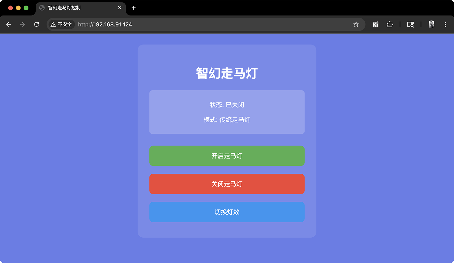
}Successfully compiled and uploaded. In the serial monitor, you can see the IP address provided by XIAO ESP32C3 as shown below. If you need Web control, access: http://192.168.91.124. Note that to access this IP address, your phone or computer needs to use the same Wi-Fi as XIAO ESP32C3.

After successful program compilation and upload, it will show the IP address available in Web mode
I connected my PC to the same Wi-Fi as XIAO and then used browser to access http://192.168.91.124
Final Version Program: Gesture+Web+MQTT Sync
Complete Feature List
✅ Gesture Control
- Four-direction gesture recognition (up, down, left, right)
- Multi-retry initialization mechanism
- Time-division detection to avoid resource conflicts
✅ Web Control Interface
- Modern responsive design
- Real-time status display
- Three control buttons + sync switch
✅ MQTT Multi-device Synchronization
- Automatic device discovery
- Real-time status synchronization
- Anti-loop message mechanism
✅ Six Light Effect Modes
- Traditional lantern
- Fire effect
- Rainbow spin
- Breathing sync
- Meteor chase
- Festival celebration
#include <Adafruit_NeoPixel.h>
#include <Wire.h>
#include <WiFi.h>
#include <AsyncTCP.h>
#include <ESPAsyncWebServer.h>
#include <ArduinoJson.h>
#include <PubSubClient.h>
#include "XLOT_APDS9960AD.h"

// WiFi settings - Please modify to your WiFi information
const char* ssid = "xiao";
const char* password = "12345678";

// MQTT settings
const char* mqtt_broker = "broker.hivemq.com";
const int mqtt_port = 1883;
const char* mqtt_topic_command = "smart_lantern/command";
const char* mqtt_topic_status = "smart_lantern/status";
const char* mqtt_topic_heartbeat = "smart_lantern/heartbeat";

// Web server and MQTT client
AsyncWebServer server(80);
WiFiClient espClient;
PubSubClient mqttClient(espClient);

// Hardware definitions
#define LED_PIN_1 9      // GPIO9 controls first LED strip
#define LED_PIN_2 8      // GPIO8 controls second LED strip
#define MOTOR_PIN 10     // GPIO10 controls motor
#define MAX_LED 14       // 14 LEDs

// I2C pin definitions
#define SDA_PIN 6        // GPIO6 - I2C data line
#define SCL_PIN 7        // GPIO7 - I2C clock line

// LED strips
Adafruit_NeoPixel strip1 = Adafruit_NeoPixel(MAX_LED, LED_PIN_1, NEO_GRB + NEO_KHZ800);
Adafruit_NeoPixel strip2 = Adafruit_NeoPixel(MAX_LED, LED_PIN_2, NEO_GRB + NEO_KHZ800);

// Gesture sensor
XLOT_APDS9960AD apds;

// PWM parameters
const int PWM_FREQ = 5000;
const int PWM_RESOLUTION = 8;

// System state
bool lanternOn = false;
int currentMode = 0;
const int TOTAL_MODES = 6;
int currentBrightness = 20;
bool gestureEnabled = false;

// Device unique identifier
String deviceId;
bool syncEnabled = true;

// Task time management
unsigned long lastGestureCheck = 0;
unsigned long lastMqttCheck = 0;
unsigned long lastHeartbeat = 0;
unsigned long lastMqttAttempt = 0;

// Task interval control
const unsigned long GESTURE_CHECK_INTERVAL = 50;    // Check gestures every 50ms
const unsigned long MQTT_CHECK_INTERVAL = 100;      // Check MQTT every 100ms
const unsigned long HEARTBEAT_INTERVAL = 30000;     // 30 second heartbeat
const unsigned long MQTT_RETRY_INTERVAL = 5000;     // 5 second reconnection interval

// Gesture control debounce
unsigned long lastGestureTime = 0;
const unsigned long GESTURE_DELAY = 800;

// Mode names
const char* modeNames[TOTAL_MODES] = {
  "Traditional Lantern", "Fire Effect", "Rainbow Spin",
  "Breathing Sync", "Meteor Chase", "Festival Mode"
};

// Mode control variables
unsigned long modeStartTime = 0;
int modeOffset = 0;

// Initialize device ID
void initDeviceId() {
  uint64_t chipId = ESP.getEfuseMac();
  char deviceIdBuffer[20];
  snprintf(deviceIdBuffer, sizeof(deviceIdBuffer), "Lantern%llX", chipId & 0xFFFFFF);
  deviceId = String(deviceIdBuffer);
  Serial.print("Device ID: ");
  Serial.println(deviceId);
}

// Helper functions
void setDualPixelColor(int pixel, uint32_t color) {
  strip1.setPixelColor(pixel, color);
  strip2.setPixelColor(pixel, color);
}

void showDualStrips() {
  strip1.show();
  strip2.show();
}

void clearDualStrips() {
  strip1.clear();
  strip2.clear();
}

uint32_t createColor(int r, int g, int b) {
  return strip1.Color(r, g, b);
}

// I2C device scanner
void scanI2CDevices() {
  Serial.println("\n=== I2C Device Scanner ===");
  byte error, address;
  int deviceCount = 0;

  for(address = 1; address < 127; address++) {
    Wire.beginTransmission(address);
    error = Wire.endTransmission();

    if (error == 0) {
      Serial.print("Device found at 0x");
      if (address < 16) {
        Serial.print("0");
      }
      Serial.print(address, HEX);

      if (address == 0x39) {
        Serial.print(" <- APDS-9960 Gesture Sensor!");
      }

      Serial.println();
      deviceCount++;
    }
  }

  if (deviceCount == 0) {
    Serial.println("No I2C devices found");
  } else {
    Serial.print("Found ");
    Serial.print(deviceCount);
    Serial.println(" I2C device(s)");
  }
  Serial.println("==========================");
}

// Enhanced gesture sensor initialization
bool initGestureSensor() {
  Serial.println("\n=== Enhanced Gesture Sensor Init ===");

  // First scan I2C devices
  scanI2CDevices();

  // Reset I2C bus
  Serial.println("Resetting I2C bus...");
  Wire.end();
  delay(100);
  Wire.begin(SDA_PIN, SCL_PIN);
  delay(500);

  // Multiple initialization attempts, reset before each attempt
  for(int attempt = 1; attempt <= 5; attempt++) {
    Serial.print("Gesture sensor init attempt ");
    Serial.print(attempt);
    Serial.print("/5: ");

    // Slight delay before each attempt
    delay(attempt * 200);

    if(apds.begin()) {
      Serial.println("SUCCESS!");

      // Verify sensor is actually usable
      delay(100);

      // Configure sensor
      Serial.println("Configuring sensor...");
      apds.enableProximity(true);
      delay(50);
      apds.enableGesture(true);
      delay(50);
      apds.setProxGain(APDS9960_PGAIN_8X);
      delay(50);
      apds.setGestureGain(APDS9960_PGAIN_8X);
      delay(50);
      apds.setGestureGain(APDS9960_AGAIN_64X);
      delay(50);
      apds.setGestureGain(APDS9960_GGAIN_8);
      delay(50);

      Serial.println("Sensor configured successfully!");

      // Test read function
      Serial.println("Testing sensor read...");
      for(int test = 0; test < 5; test++) {
        uint8_t testGesture = apds.readGesture();
        delay(100);
      }
      Serial.println("Sensor test completed!");

      return true;
    } else {
      Serial.println("FAILED");

      // Re-scan I2C after failures
      if(attempt == 3) {
        Serial.println("Re-scanning I2C after failures...");
        scanI2CDevices();
      }
    }
  }

  Serial.println("All gesture sensor init attempts failed!");
  return false;
}

// WiFi connection
void connectToWiFi() {
  Serial.println("Connecting to WiFi...");
  WiFi.mode(WIFI_STA);
  WiFi.begin(ssid, password);

  int retries = 0;
  while (WiFi.status() != WL_CONNECTED && retries < 20) {
    delay(500);
    Serial.print(".");
    retries++;
  }

  if (WiFi.status() == WL_CONNECTED) {
    Serial.println("");
    Serial.println("WiFi connected successfully!");
    Serial.print("IP address: ");
    Serial.println(WiFi.localIP());
  } else {
    Serial.println("");
    Serial.println("WiFi connection failed!");
  }
}

// MQTT connection
void connectToMQTT() {
  if (!mqttClient.connected() && WiFi.status() == WL_CONNECTED) {
    if (millis() - lastMqttAttempt > MQTT_RETRY_INTERVAL) {
      lastMqttAttempt = millis();

      if (mqttClient.connect(deviceId.c_str())) {
        Serial.println("MQTT connected successfully!");

        // Subscribe to topics
        mqttClient.subscribe(mqtt_topic_command);
        mqttClient.subscribe(mqtt_topic_status);
        mqttClient.subscribe(mqtt_topic_heartbeat);

        // Send online notification
        publishHeartbeat();
        publishStatus();
      } else {
        Serial.print("MQTT connection failed, error code: ");
        Serial.println(mqttClient.state());
      }
    }
  }
}

// Publish heartbeat message
void publishHeartbeat() {
  if (mqttClient.connected()) {
    DynamicJsonDocument doc(256);
    doc["deviceId"] = deviceId;
    doc["timestamp"] = millis();
    doc["ip"] = WiFi.localIP().toString();
    doc["status"] = "online";

    String message;
    serializeJson(doc, message);

    mqttClient.publish(mqtt_topic_heartbeat, message.c_str());
  }
}

// Publish status message
void publishStatus() {
  if (mqttClient.connected()) {
    DynamicJsonDocument doc(256);
    doc["deviceId"] = deviceId;
    doc["lanternOn"] = lanternOn;
    doc["currentMode"] = currentMode;
    doc["modeName"] = modeNames[currentMode];
    doc["timestamp"] = millis();

    String message;
    serializeJson(doc, message);

    mqttClient.publish(mqtt_topic_status, message.c_str());
  }
}

// Publish control command
void publishCommand(const String& command, const String& source = "gesture") {
  if (mqttClient.connected() && syncEnabled) {
    DynamicJsonDocument doc(256);
    doc["deviceId"] = deviceId;
    doc["command"] = command;
    doc["source"] = source;
    doc["lanternOn"] = lanternOn;
    doc["currentMode"] = currentMode;
    doc["timestamp"] = millis();

    String message;
    serializeJson(doc, message);

    bool published = mqttClient.publish(mqtt_topic_command, message.c_str());
    if (published) {
      Serial.print("Published command: ");
      Serial.println(command);
    }
  }
}

// MQTT message callback
void onMqttMessage(char* topic, byte* payload, unsigned int length) {
  String message;
  for (int i = 0; i < length; i++) {
    message += (char)payload[i];
  }

  // Parse JSON message
  DynamicJsonDocument doc(512);
  DeserializationError error = deserializeJson(doc, message);

  if (error) {
    return; // Silently ignore parsing errors
  }

  String senderId = doc["deviceId"];

  // Ignore messages from self
  if (senderId == deviceId) {
    return;
  }

  // Handle different types of messages
  String topicStr = String(topic);

  if (topicStr == mqtt_topic_command) {
    String command = doc["command"];

    Serial.print("Received sync command: ");
    Serial.print(command);
    Serial.print(" (from: ");
    Serial.print(senderId);
    Serial.println(")");

    // Execute sync commands
    if (command == "turn_on") {
      if (!lanternOn) {
        lanternOn = true;
        modeStartTime = millis();
        modeOffset = 0;
        showStartupAnimation();
      }
    }
    else if (command == "turn_off") {
      if (lanternOn) {
        lanternOn = false;
        showShutdownAnimation();
        ledcWrite(MOTOR_PIN, 0);
        clearDualStrips();
        showDualStrips();
      }
    }
    else if (command == "switch_mode") {
      if (lanternOn) {
        int newMode = doc["currentMode"];
        if (newMode >= 0 && newMode < TOTAL_MODES) {
          currentMode = newMode;
          modeStartTime = millis();
          modeOffset = 0;
          showModeIndicator();
        }
      }
    }
  }
  else if (topicStr == mqtt_topic_heartbeat) {
    String status = doc["status"];
    if (status == "online") {
      Serial.print("Device online: ");
      Serial.println(senderId);
    }
  }
}

// Web server setup
void setupWebServer() {
  // Homepage
  server.on("/", HTTP_GET, [](AsyncWebServerRequest *request) {
    String html = "<!DOCTYPE html><html><head><meta charset='UTF-8'>";
    html += "<title>Smart Lantern Control</title>";
    html += "<style>body{font-family:Arial;text-align:center;background:#667eea;color:white;padding:20px}";
    html += ".container{background:rgba(255,255,255,0.1);padding:30px;border-radius:15px;max-width:400px;margin:0 auto}";
    html += "button{width:100%;padding:15px;margin:10px 0;border:none;border-radius:10px;font-size:16px;cursor:pointer}";
    html += ".btn-on{background:#4CAF50;color:white}";
    html += ".btn-off{background:#f44336;color:white}";
    html += ".btn-switch{background:#2196F3;color:white}";
    html += ".btn-sync{background:#FF9800;color:white}";
    html += ".status{background:rgba(255,255,255,0.2);padding:10px;border-radius:8px;margin:20px 0}";
    html += "</style></head><body>";
    html += "<div class='container'>";
    html += "<h1>🏮 Smart Lantern</h1>";
    html += "<div class='status'>";
    html += "<p>Status: <span id='status'>Loading...</span></p>";
    html += "<p>Mode: <span id='mode'>Loading...</span></p>";
    html += "<p>Device: <span id='deviceId'>Loading...</span></p>";
    html += "<p>MQTT: <span id='mqttStatus'>Loading...</span></p>";
    html += "<p>Gesture: <span id='gestureStatus'>Loading...</span></p>";
    html += "</div>";
    html += "<button class='btn-on' onclick='sendCmd(\"on\")'>🔆 Turn On</button>";
    html += "<button class='btn-off' onclick='sendCmd(\"off\")'>🔅 Turn Off</button>";
    html += "<button class='btn-switch' onclick='sendCmd(\"switch\")'>🎨 Switch Mode</button>";
    html += "<button class='btn-sync' onclick='sendCmd(\"toggle_sync\")'>🔄 Sync: <span id='syncStatus'>Loading...</span></button>";
    html += "</div>";
    html += "<script>";
    html += "var modes=['Traditional Lantern','Fire Effect','Rainbow Spin','Breathing Sync','Meteor Chase','Festival Mode'];";
    html += "function updateStatus(){";
    html += "fetch('/api/status').then(r=>r.json()).then(d=>{";
    html += "document.getElementById('status').innerText=d.on?'On':'Off';";
    html += "document.getElementById('mode').innerText=modes[d.mode]||'Unknown';";
    html += "document.getElementById('deviceId').innerText=d.deviceId||'Unknown';";
    html += "document.getElementById('mqttStatus').innerText=d.mqttConnected?'Connected':'Disconnected';";
    html += "document.getElementById('gestureStatus').innerText=d.gestureEnabled?'Available':'Unavailable';";
    html += "document.getElementById('syncStatus').innerText=d.syncEnabled?'On':'Off';";
    html += "}).catch(e=>console.error(e));}";
    html += "function sendCmd(cmd){";
    html += "fetch('/api/control',{method:'POST',headers:{'Content-Type':'application/x-www-form-urlencoded'},";
    html += "body:'command='+cmd}).then(r=>r.json()).then(d=>{";
    html += "if(d.success)setTimeout(updateStatus,200);";
    html += "}).catch(e=>console.error(e));}";
    html += "updateStatus();setInterval(updateStatus,3000);";
    html += "</script></body></html>";

    request->send(200, "text/html", html);
  });

  // API: Get status
  server.on("/api/status", HTTP_GET, [](AsyncWebServerRequest *request) {
    DynamicJsonDocument doc(256);
    doc["on"] = lanternOn;
    doc["mode"] = currentMode;
    doc["deviceId"] = deviceId;
    doc["mqttConnected"] = mqttClient.connected();
    doc["syncEnabled"] = syncEnabled;
    doc["gestureEnabled"] = gestureEnabled;

    String response;
    serializeJson(doc, response);
    request->send(200, "application/json", response);
  });

  // API: Control commands
  server.on("/api/control", HTTP_POST, [](AsyncWebServerRequest *request) {
    DynamicJsonDocument responseDoc(128);
    responseDoc["success"] = false;
    responseDoc["message"] = "Invalid request";

    if (request->hasParam("command", true)) {
      String command = request->getParam("command", true)->value();

      if (command == "on") {
        if (!lanternOn) {
          turnOnLantern();
          publishCommand("turn_on", "web");
          responseDoc["success"] = true;
          responseDoc["message"] = "Lantern turned on";
        }
      }
      else if (command == "off") {
        if (lanternOn) {
          turnOffLantern();
          publishCommand("turn_off", "web");
          responseDoc["success"] = true;
          responseDoc["message"] = "Lantern turned off";
        }
      }
      else if (command == "switch") {
        if (lanternOn) {
          switchMode(1);
          publishCommand("switch_mode", "web");
          responseDoc["success"] = true;
          responseDoc["message"] = String("Switched to: ") + modeNames[currentMode];
        }
      }
      else if (command == "toggle_sync") {
        syncEnabled = !syncEnabled;
        responseDoc["success"] = true;
        responseDoc["message"] = String("Sync ") + (syncEnabled ? "enabled" : "disabled");
      }
    }

    String response;
    serializeJson(responseDoc, response);
    request->send(200, "application/json", response);
  });

  server.begin();
  Serial.println("Web server started");
}

// Enhanced gesture handling function
void handleGestures() {
  // Time-division checking to avoid conflicts with MQTT
  if (millis() - lastGestureCheck < GESTURE_CHECK_INTERVAL) {
    return;
  }
  lastGestureCheck = millis();

  if (!gestureEnabled) {
    return;
  }

  // Add sensor health check
  static unsigned long lastHealthCheck = 0;
  if (millis() - lastHealthCheck > 30000) { // Check every 30 seconds
    lastHealthCheck = millis();
    Serial.println("Gesture sensor health check...");

    // Try simple I2C communication
    Wire.beginTransmission(0x39);
    byte error = Wire.endTransmission();

    if (error != 0) {
      Serial.println("Gesture sensor I2C communication failed!");
      Serial.print("Error code: ");
      Serial.println(error);

      // Try reinitialize
      Serial.println("Attempting to reinitialize sensor...");
      gestureEnabled = initGestureSensor();
    } else {
      Serial.println("Gesture sensor I2C OK");
    }
  }

  uint8_t gesture = apds.readGesture();

  if (gesture != 0) {
    if (millis() - lastGestureTime < GESTURE_DELAY) {
      return;
    }
    lastGestureTime = millis();

    Serial.println("=== GESTURE DETECTED ===");
    Serial.print("Timestamp: ");
    Serial.println(millis());
    Serial.print("Gesture code: ");
    Serial.println(gesture);

    switch (gesture) {
      case APDS9960_LEFT:
        Serial.println("Action: LEFT (previous mode)");
        switchMode(-1);
        publishCommand("switch_mode", "gesture");
        break;

      case APDS9960_RIGHT:
        Serial.println("Action: RIGHT (next mode)");
        switchMode(1);
        publishCommand("switch_mode", "gesture");
        break;

      case APDS9960_UP:
        Serial.println("Action: UP (turn on lantern)");
        turnOnLantern();
        publishCommand("turn_on", "gesture");
        break;

      case APDS9960_DOWN:
        Serial.println("Action: DOWN (turn off lantern)");
        turnOffLantern();
        publishCommand("turn_off", "gesture");
        break;

      default:
        Serial.print("Unknown gesture code: ");
        Serial.println(gesture);
        break;
    }
    Serial.println("========================");
  }

  // Debug info: periodically display gesture detection status
  static unsigned long lastStatusReport = 0;
  if (millis() - lastStatusReport > 60000) { // Report every minute
    lastStatusReport = millis();
    Serial.print("Gesture system status - Enabled: ");
    Serial.print(gestureEnabled ? "YES" : "NO");
    Serial.print(", Check interval: ");
    Serial.print(GESTURE_CHECK_INTERVAL);
    Serial.println("ms");
  }
}

// Switch mode
void switchMode(int direction) {
  if (!lanternOn) {
    return;
  }

  currentMode += direction;
  if (currentMode < 0) {
    currentMode = TOTAL_MODES - 1;
  } else if (currentMode >= TOTAL_MODES) {
    currentMode = 0;
  }

  modeStartTime = millis();
  modeOffset = 0;

  showModeIndicator();
  publishStatus();
}

// Turn on lantern
void turnOnLantern() {
  if (lanternOn) {
    return;
  }

  lanternOn = true;
  modeStartTime = millis();
  modeOffset = 0;

  showStartupAnimation();
  publishStatus();
}

// Turn off lantern
void turnOffLantern() {
  if (!lanternOn) {
    return;
  }

  lanternOn = false;
  showShutdownAnimation();

  ledcWrite(MOTOR_PIN, 0);
  clearDualStrips();
  showDualStrips();
  publishStatus();
}

// Show mode indicator
void showModeIndicator() {
  clearDualStrips();

  uint32_t indicatorColor;
  switch(currentMode) {
    case 0: indicatorColor = createColor(60, 20, 0); break;  // Orange
    case 1: indicatorColor = createColor(50, 0, 0); break;   // Red
    case 2: indicatorColor = createColor(25, 25, 25); break; // White
    case 3: indicatorColor = createColor(50, 50, 0); break;  // Yellow
    case 4: indicatorColor = createColor(0, 50, 50); break;  // Cyan
    case 5: indicatorColor = createColor(50, 0, 50); break;  // Purple
  }

  for (int i = 0; i <= currentMode; i++) {
    setDualPixelColor(i, indicatorColor);
  }
  showDualStrips();
  delay(500);

  clearDualStrips();
  showDualStrips();
}

// Startup animation
void showStartupAnimation() {
  for (int i = 0; i < MAX_LED; i++) {
    setDualPixelColor(i, createColor(0, 50, 0));
    showDualStrips();
    delay(50);
  }

  for (int speed = 0; speed <= 120; speed += 10) {
    ledcWrite(MOTOR_PIN, speed);
    delay(30);
  }

  clearDualStrips();
  showDualStrips();
}

// Shutdown animation
void showShutdownAnimation() {
  int currentSpeed = 120;
  while (currentSpeed > 0) {
    ledcWrite(MOTOR_PIN, currentSpeed);
    currentSpeed -= 10;
    delay(50);
  }
  ledcWrite(MOTOR_PIN, 0);

  for (int i = MAX_LED - 1; i >= 0; i--) {
    setDualPixelColor(i, createColor(0, 0, 0));
    showDualStrips();
    delay(50);
  }
}

// Run current mode
void runCurrentMode() {
  if (!lanternOn) {
    return;
  }

  switch(currentMode) {
    case 0: traditionalLanternMode(); break;
    case 1: fireMode(); break;
    case 2: rainbowSpinMode(); break;
    case 3: breathingSyncMode(); break;
    case 4: meteorChaseMode(); break;
    case 5: festivalMode(); break;
  }
}

// Mode 1: Traditional lantern
void traditionalLanternMode() {
  uint32_t colors[] = {
    createColor(50, 0, 0),   // Red
    createColor(60, 20, 0),  // Orange
    createColor(50, 50, 0),  // Yellow
    createColor(0, 50, 0),   // Green
    createColor(0, 50, 50),  // Cyan
    createColor(0, 0, 50)    // Blue
  };
  int numColors = 6;

  ledcWrite(MOTOR_PIN, 120);

  for(int i = 0; i < MAX_LED; i++) {
    int colorIndex = (i + modeOffset) % numColors;
    setDualPixelColor(i, colors[colorIndex]);
  }
  showDualStrips();

  if (millis() - modeStartTime > (modeOffset + 1) * 200) {
    modeOffset++;
  }
}

// Mode 2: Fire effect
void fireMode() {
  int motorSpeed = 80 + random(-15, 15);
  ledcWrite(MOTOR_PIN, motorSpeed);

  for(int i = 0; i < MAX_LED; i++) {
    int flicker = random(20, 80);
    int r = flicker;
    int g = flicker * 0.3;
    int b = 0;
    setDualPixelColor(i, createColor(r, g, b));
  }
  showDualStrips();
}

// Mode 3: Rainbow spin
void rainbowSpinMode() {
  ledcWrite(MOTOR_PIN, 120);

  for(int i = 0; i < MAX_LED; i++) {
    int phase = ((i * 255 / MAX_LED) + (modeOffset * 10)) % 255;
    int r = 0, g = 0, b = 0;

    if(phase < 85) {
      r = (255 - phase * 3) / 5;
      g = (phase * 3) / 5;
      b = 0;
    } else if(phase < 170) {
      phase -= 85;
      r = 0;
      g = (255 - phase * 3) / 5;
      b = (phase * 3) / 5;
    } else {
      phase -= 170;
      r = (phase * 3) / 5;
      g = 0;
      b = (255 - phase * 3) / 5;
    }

    setDualPixelColor(i, createColor(r, g, b));
  }
  showDualStrips();

  if (millis() - modeStartTime > (modeOffset + 1) * 100) {
    modeOffset++;
    if (modeOffset > 25) modeOffset = 0;
  }
}

// Mode 4: Breathing sync - simplified version
void breathingSyncMode() {
  unsigned long cycleTime = (millis() - modeStartTime) % 4000;
  int breathLevel = (cycleTime < 2000) ?
    map(cycleTime, 0, 2000, 0, 50) : map(cycleTime, 2000, 4000, 50, 0);

  for(int i = 0; i < MAX_LED; i++) {
    setDualPixelColor(i, createColor(breathLevel, breathLevel/2, 0));
  }
  showDualStrips();

  ledcWrite(MOTOR_PIN, 50 + breathLevel * 2);
}

// Mode 5: Meteor chase
void meteorChaseMode() {
  ledcWrite(MOTOR_PIN, 180);

  int position = (modeOffset) % MAX_LED;

  clearDualStrips();

  setDualPixelColor(position, createColor(30, 30, 30));

  for (int i = 1; i <= 3; i++) {
    int tailPos = (position - i + MAX_LED) % MAX_LED;
    int brightness = 30 - (i * 8);
    if (brightness > 0) {
      setDualPixelColor(tailPos, createColor(brightness, brightness, brightness));
    }
  }

  showDualStrips();

  if (millis() - modeStartTime > (modeOffset + 1) * 50) {
    modeOffset++;
  }
}

// Mode 6: Festival celebration
void festivalMode() {
  uint32_t festiveColors[] = {
    createColor(50, 0, 0),   // Red
    createColor(0, 50, 0),   // Green
    createColor(50, 50, 0),  // Yellow
    createColor(0, 0, 50),   // Blue
    createColor(50, 0, 50)   // Purple
  };

  ledcWrite(MOTOR_PIN, 130);

  for(int i = 0; i < MAX_LED; i++) {
    if(random(10) > 7) {
      setDualPixelColor(i, festiveColors[random(5)]);
    } else {
      setDualPixelColor(i, createColor(0, 0, 0));
    }
  }
  showDualStrips();

  if(random(100) > 95) {
    ledcWrite(MOTOR_PIN, 100 + random(60));
  }
}

// MQTT maintenance task
void maintainMQTT() {
  if (millis() - lastMqttCheck < MQTT_CHECK_INTERVAL) {
    return;
  }
  lastMqttCheck = millis();

  if (!mqttClient.connected()) {
    connectToMQTT();
  } else {
    mqttClient.loop();

    // Send heartbeat
    if (millis() - lastHeartbeat > HEARTBEAT_INTERVAL) {
      publishHeartbeat();
      lastHeartbeat = millis();
    }
  }
}

void setup() {
  Serial.begin(115200);
  delay(3000);

  Serial.println("=== Smart Lantern Debug Enhanced Version ===");
  Serial.println("Version: Complete Debug v1.0");

  // Initialize device ID
  initDeviceId();

  // First initialize LED and motor (before WiFi)
  Serial.println("Initializing LED strips...");
  strip1.begin();
  strip1.setBrightness(currentBrightness);
  strip1.clear();
  strip1.show();

  strip2.begin();
  strip2.setBrightness(currentBrightness);
  strip2.clear();
  strip2.show();

  Serial.println("Initializing motor...");
  ledcAttach(MOTOR_PIN, PWM_FREQ, PWM_RESOLUTION);
  ledcWrite(MOTOR_PIN, 0);

  // Early gesture sensor initialization (before WiFi)
  Serial.println("Early gesture sensor initialization...");
  Wire.begin(SDA_PIN, SCL_PIN);
  delay(1000);  // Give sensor more startup time

  gestureEnabled = initGestureSensor();

  // Connect WiFi
  connectToWiFi();

  // Setup MQTT and web server (after gesture sensor)
  if (WiFi.status() == WL_CONNECTED) {
    Serial.println("Setting up MQTT...");
    mqttClient.setServer(mqtt_broker, mqtt_port);
    mqttClient.setCallback(onMqttMessage);

    // Delayed MQTT startup to avoid conflicts with gesture sensor
    delay(1000);
    connectToMQTT();

    Serial.println("Setting up Web server...");
    setupWebServer();
  }

  Serial.println("\n=== System Status ===");
  Serial.println("Control Methods:");
  if (gestureEnabled) {
    Serial.println("  ✅ Gesture Control: Available");
    Serial.println("     UP: Turn on lantern");
    Serial.println("     DOWN: Turn off lantern");
    Serial.println("     LEFT/RIGHT: Switch light modes");
  } else {
    Serial.println("  ❌ Gesture Control: Unavailable");
    Serial.println("     Check I2C connections and sensor wiring");
  }

  if (WiFi.status() == WL_CONNECTED) {
    Serial.println("  ✅ Web Control: Available");
    Serial.print("     Access: http://");
    Serial.println(WiFi.localIP());

    Serial.println("  ✅ MQTT Sync: Available");
    Serial.print("     Device ID: ");
    Serial.println(deviceId);
    Serial.print("     MQTT Status: ");
    Serial.println(mqttClient.connected() ? "Connected" : "Connecting...");
  } else {
    Serial.println("  ❌ WiFi: Not connected");
  }

  Serial.println("\nDebug Features:");
  Serial.println("  • Enhanced I2C scanning");
  Serial.println("  • Multi-retry gesture sensor init");
  Serial.println("  • Periodic health checks");
  Serial.println("  • Detailed gesture detection logs");

  Serial.println("\n🚀 System Ready!");
  Serial.println("Watch serial monitor for gesture detection and health reports");

  // Startup indicator animation
  for(int i = 0; i < 3; i++) {
    setDualPixelColor(0, createColor(0, 50, 0));
    showDualStrips();
    delay(200);
    clearDualStrips();
    showDualStrips();
    delay(200);
  }

  // Final health check report
  Serial.println("\n=== Initial Health Check ===");
  Serial.print("Gesture sensor: ");
  Serial.println(gestureEnabled ? "READY" : "FAILED");
  Serial.print("WiFi: ");
  Serial.println(WiFi.status() == WL_CONNECTED ? "CONNECTED" : "FAILED");
  Serial.print("MQTT: ");
  Serial.println(mqttClient.connected() ? "CONNECTED" : "PENDING");
  Serial.println("=============================");
}

void loop() {
  // Time-division task scheduling to avoid resource conflicts

  // Task 1: Gesture detection (50ms interval) - high priority
  handleGestures();

  // Task 2: Light effect operation (real-time)
  runCurrentMode();

  // Task 3: MQTT maintenance (100ms interval)
  maintainMQTT();

  // Task 4: WiFi monitoring (reduced frequency)
  static unsigned long lastWifiCheck = 0;
  if (millis() - lastWifiCheck > 10000) {  // Check WiFi every 10 seconds
    if (WiFi.status() != WL_CONNECTED) {
      Serial.println("WiFi reconnecting...");
      WiFi.reconnect();
    }
    lastWifiCheck = millis();
  }

  // Main loop delay (reduce CPU usage)
  delay(10);
}Testing the final program, it fully implemented 3 control methods. Below is a screenshot of the final version's Web access:
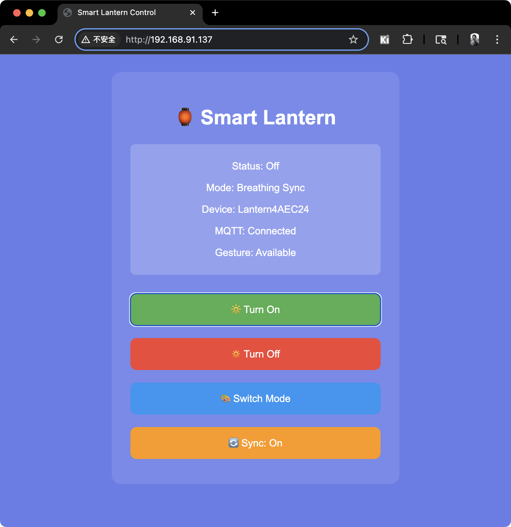
Direct control of XIAO ESP32C3 through web access
Finally manufactured 2 revolving lanterns for multi-lantern synchronization testing.
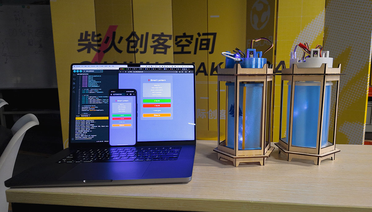
Successfully completed testing of the final program, fully implementing 3 control methods
The video below demonstrates successful control of the lantern in 3 ways.
Manufacturing Journey: 18 Weeks of Growth
Phase One: Conception and Design (Weeks 1-6)
The initial idea for the project was simple: make something that lights up. But as I delved deeper into the Fab Academy course, this "thing that lights up" gradually gained clear direction and complex functionality.
| Week | Milestone | Status | Achievement |
|---|---|---|---|
| Week 1 | Project Conception & Requirements Analysis | ✅ | 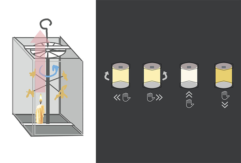 |
| Week 2 | 3D Modeling Design | ✅ | 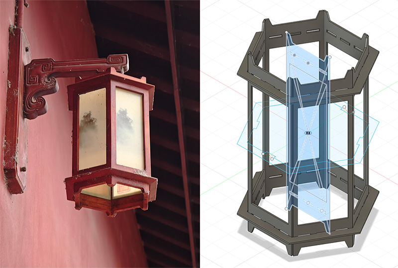 |
| Week 3 | Laser Cut Shell | ✅ | 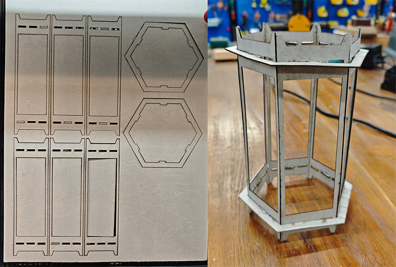 |
| Week 6 | PCB Circuit Design | ✅ | 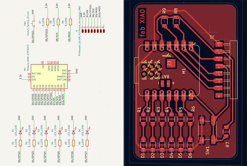 |
The biggest gain from this phase was learning how to transform vague ideas into concrete solutions. Initially, I just wanted to make a "smart lamp," but through requirements analysis, technical research, and feasibility assessment, I finally settled on the revolving lantern as a culturally rich carrier.
Phase Two: Core Technology Breakthrough (Weeks 7-11)
Entering the technical implementation phase, every week was a new challenge. PCB production, sensor debugging, motor control—each link required repeated trial and error and optimization.
| Week | Milestone | Status | Achievement |
|---|---|---|---|
| Week 8 | PCB Production & Soldering | ✅ | 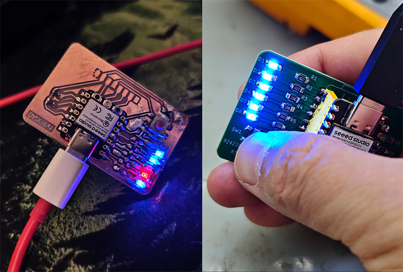 |
| Week 9 | Gesture Sensor Integration | ✅ | 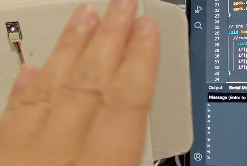 |
| Week 10 | Motor & LED Control | ✅ | 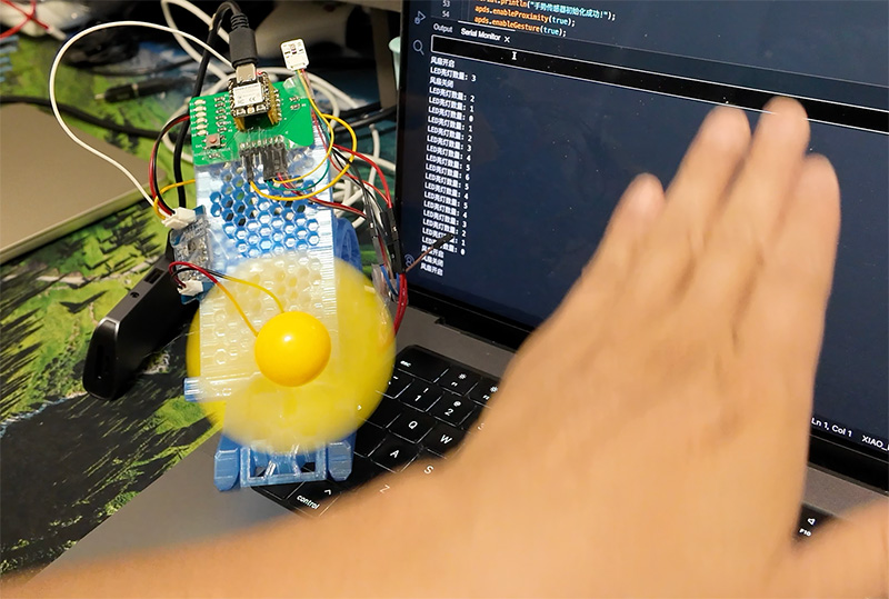 |
| Week 11 | Network Communication Implementation | ✅ | 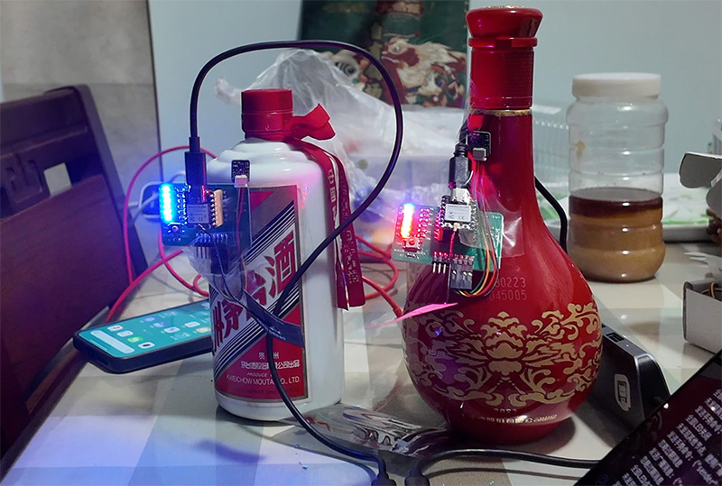 |
The key breakthrough in this phase was solving the problem of multi-sensor collaborative work. How do three gesture sensors avoid interfering with each other? How to achieve real-time gesture recognition with limited computing power? These all required finding optimal solutions through practice.
Phase Three: System Integration and Optimization (Weeks 12-17)
After technical verification was completed, came the most challenging system integration phase. How to integrate scattered functional modules into a harmonious whole?
| Week | Milestone | Status | Achievement |
|---|---|---|---|
| Week 15 | Web Control Interface | ✅ | 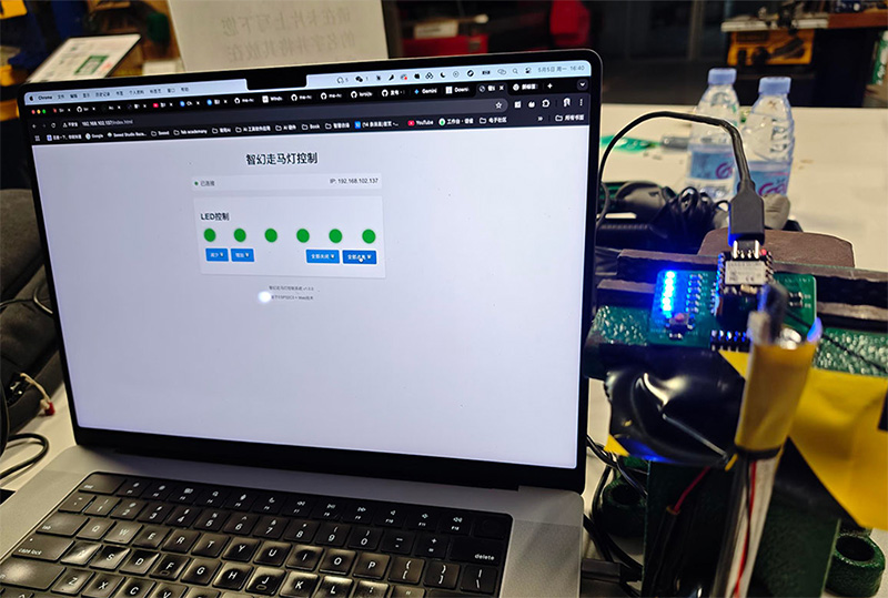 |
| Week 16 | Mechanical Structure Integration | ✅ | 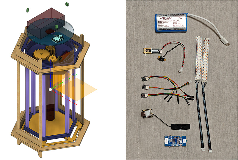 |
| Week 17 | Circular PCB Design | ✅ | 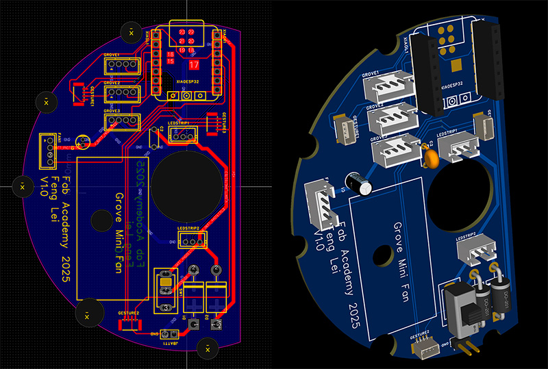 |
Week 17's PCB design had many problems discovered during the first board's soldering and testing. After troubleshooting and revision, the final PCB design and production were completed.
Current Status: Main Body Fully Complete
Completed Parts ✅
Hardware Manufacturing Completion: 100%
- Laser-cut wooden shell: Perfect ✨
- 3D-printed gear system: Smooth operation ✨
- Circular PCB: Manufacturing complete, soldering in place ✨
- Motor control: Testing passed ✨
- LED light effects: Brilliant and colorful ✨
Software Development Completion: 100%
- Basic firmware: Stable operation ✨
- Gesture recognition: Algorithm verified ✨
- Web interface: Fully functional ✨
- WiFi communication: Stable connection ✨
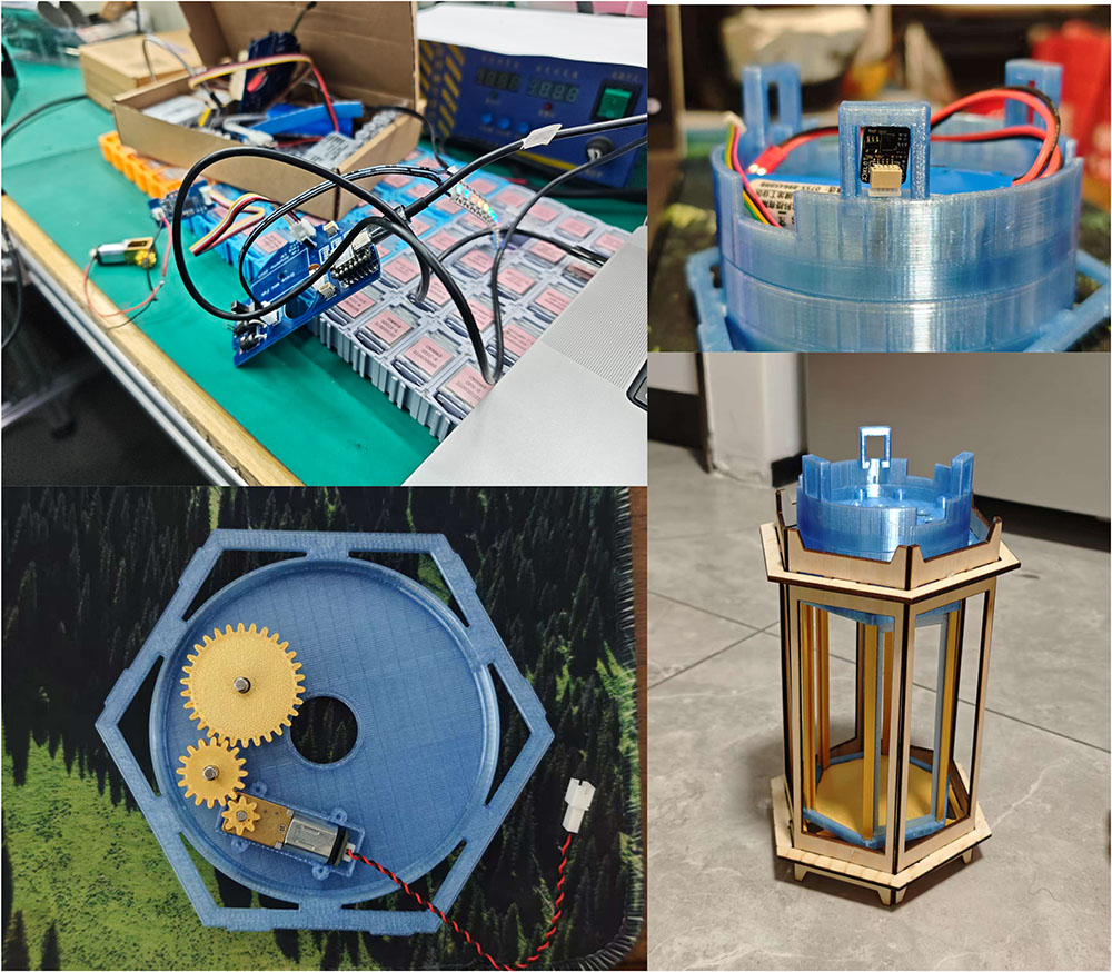
Current status: Main functions implemented, undergoing final integration and debugging
Minor Hiccups Encountered ⚠️
PCB Design Errors
At the final stages of the project, I discovered a basic error: the gesture sensor, LED strip, and motor control board interface pin sequences on Version 3 PCB were all designed in reverse! This was like installing a reverse steering wheel in a car—all directions were backwards.
Problem Analysis: When designing the PCB, I referenced incorrect pin diagrams, causing wire sequence reversal. Although no components were damaged (thankfully there were protection circuits), the sensors, light strips, and motor couldn't work properly.
Solution: Designed Version 4 PCB
Gear Continuous Operation Problem
After assembling the entire Magical Revolving Lantern, testing quickly revealed frequent stuttering. I removed the PCB compartment to observe and found that C2A was being pushed up after running for a while, causing it to lose grip, as shown in the video below.
So I tried modifying the C2B and C2A gears, as shown below. I increased the gear height from 4mm to 5mm, then added another 4mm wrapper on the shaft part to allow the gears to fit more tightly with the steel shaft.
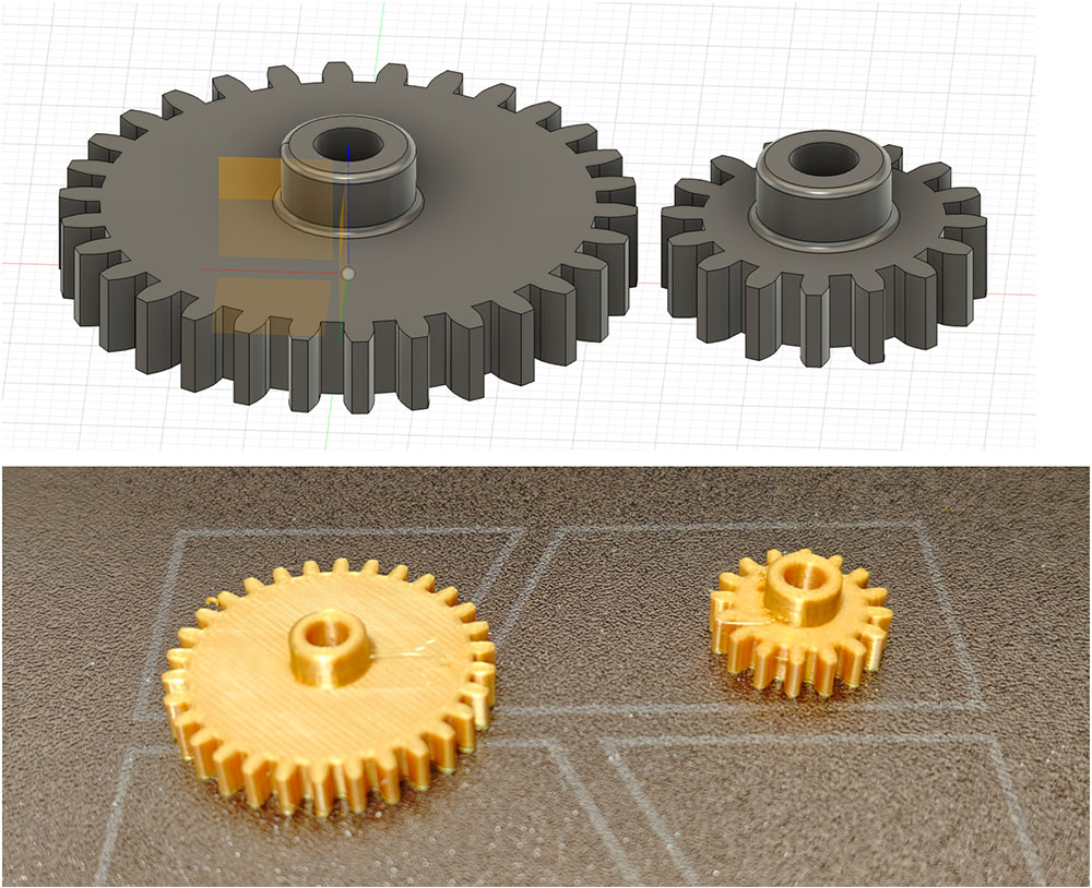
Redesigned and printed C2B and C2A gears
After replacement, the lantern's rotational stability improved significantly.
This minor incident gave me a deep appreciation for the power of "Murphy's Law" in project management: anything that can go wrong will go wrong. Fortunately, I had reserved enough time buffer, so this small problem wouldn't affect the final demonstration.
Detailed Technical Specifications
Materials and Cost Analysis
The entire project's total cost was controlled within 250 RMB, which is quite economical for similar smart hardware products.
Cost breakdown: Electronic components account for the major portion, mechanical material costs are relatively low
BOM
| No. | Name | Quantity | Comment | Designator | Footprint | Pin Count | Manufacturer | LCSC Price | Total price(RMB) |
|---|---|---|---|---|---|---|---|---|---|
| 1 | 10uF | 1 | 10uF | C1 | CAP-TH_BD4.0-P1.50-D0.8-FD | 2 | HUAWEI(华威集团) | 0.1292 | 0.13 |
| 2 | 100nF | 1 | 100nF | C2 | CAP-TH_L5.0-W2.5-P5.00-D1.0 | 2 | Dersonic(德尔创) | 0.1216 | 0.12 |
| 3 | WAFER-PH2.0-4PZZ | 4 | WAFER-PH2.0-4PZZ | FAN1,GROVE1,GROVE2,GROVE3 | CONN-TH_4P-P2.00_FWF20001-S04S22W5B | 4 | XUNPU(讯普) | 0.1045 | 0.42 |
| 4 | 1.0T-4P立贴 | 3 | 1.0T-4P立贴 | GESTURE1,GESTURE2,GESTURE3 | CONN-SMD_1.0T-4P-LT | 6 | BOOMELE(博穆精密) | 0.3802 | 1.14 |
| 5 | PZ254V-11-02P | 1 | PZ254V-11-02P | JBATT1 | HDR-TH_2P-P2.54-V-M | 2 | XFCN(兴飞) | 0.0851 | 0.09 |
| 6 | WAFER-PH2.0-3PZZ | 2 | WAFER-PH2.0-3PZZ | LEDSTRIP1,LEDSTRIP2 | CONN-TH_PH2.0D-L-3P | 3 | XUNPU(讯普) | 0.0791 | 0.16 |
| 7 | SS-12D10-G090 | 1 | SS-12D10-G090 | SW1 | SW-TH_3P-L12.7-W6.6-P4.70_C9900034369 | 3 | G-Switch(品赞) | 1.801 | 1.80 |
| 8 | XIAOESP32C3 | 1 | XIAOESP32C3 | XIAOESP32C3 | CONN-SMD_113991054 | 23 | Seeed Studio(矽递科技) | 35 | 35.00 |
| 9 | 2541FV-7P-B | 2 | 2541FV-7P-B | XIAOL1,XIAOR1 | HDR-TH_7P-P2.54-V-F | 7 | HanElectricity(瀚源) | 0.2922 | 0.58 |
| 10 | XLOT APDS-9960 手势传感器 | 3 | APDS-9960 | XLOT | JST PH2.0mm | 4 | XLOT | 30 | 90.00 |
| 11 | 拓竹 N20-10D侧出轴电机-25rpm (1个)- LA008 bambulab(Toy motor) | 1 | N20-10D LA008 bambulab | N20-10D | SH1.0mm-2P | 2 | Bambu lab | 29 | 29.00 |
| 12 | 劲爽5V伏大电流锂电池(Powerful 5V high current lithium battery) | 1 | JST2.54 | 2 | 劲爽电池 | 30 | 30.00 | ||
| 13 | 可编程全彩RGB灯条 | 2 | 14灯珠 RGB灯条(14 LED beads RGB light strip) | PH2.0 | 3 | 亚博智能 Yahboom | 13 | 26.00 | |
| 14 | 椴木板(Limestone board) | 1 | 60cm80cm3mm | 30 | 30.00 | ||||
| 15 | 3D打印 PLA/PETG 材料 3D Printing PLA/PETG Materials | 1 | Bambu | 20 | 20.00 | ||||
| 16 | Grove - Universal 4 Pin 20cm Unbuckled Cable | 1 | Seeed Studio(矽递科技) | 4 | 4.00 | ||||
| 17 | 4mm直径钢轴(4mm Diameter Steel Shaft) | 2 | 直径4mm,长度20mm Diameter 4mm, length 20mm | 劲功 | 0.04 | 0.08 | |||
| SUM | 268.52 |
Performance Indicators
Response Performance:
- Gesture recognition delay: < 200ms
- LED color switching: < 50ms
- WiFi connection time: < 3s
- Motor startup time: < 500ms
- MQTT synchronization: <2s
Battery Life:
- Normal usage mode: About 4 hours
Interaction Range:
- Gesture recognition distance: 5-30cm
- WiFi control distance: About 50 meters
- Multi-device sync: Theoretically any Magical Revolving Lanterns subscribing to the same MQTT channel can achieve synchronization
Comprehensive Application of Digital Manufacturing Skills
This project used almost all manufacturing technologies taught in Fab Academy:
📐 2D/3D Design
- Fusion 360: Entire lantern structure, including complex gear systems and assembly design
- EasyEDA: Circuit schematics and PCB layout
⚙️ Subtractive Manufacturing
- Laser cutting: Precision wooden shell cutting
- CNC milling: PCB circuit board manufacturing
- Vinyl cutting: Traditional Chinese paper-cut style patterns on lantern cover panels
🖨️ Additive Manufacturing
- FDM 3D printing: Complex gears and support structures
- Multi-color printing: Enhanced visual effects
🔌 Electronic Manufacturing
- Double-sided PCB design: Based on single-sided PCB design, challenged double-layer PCB design, complete process from schematic to finished product
- Commercial PCB production: Double-layer PCB manufacturing through JLC
- Electronic component soldering: Various connector and component soldering processes
- Debugging and testing: Application of oscilloscopes and logic analyzers
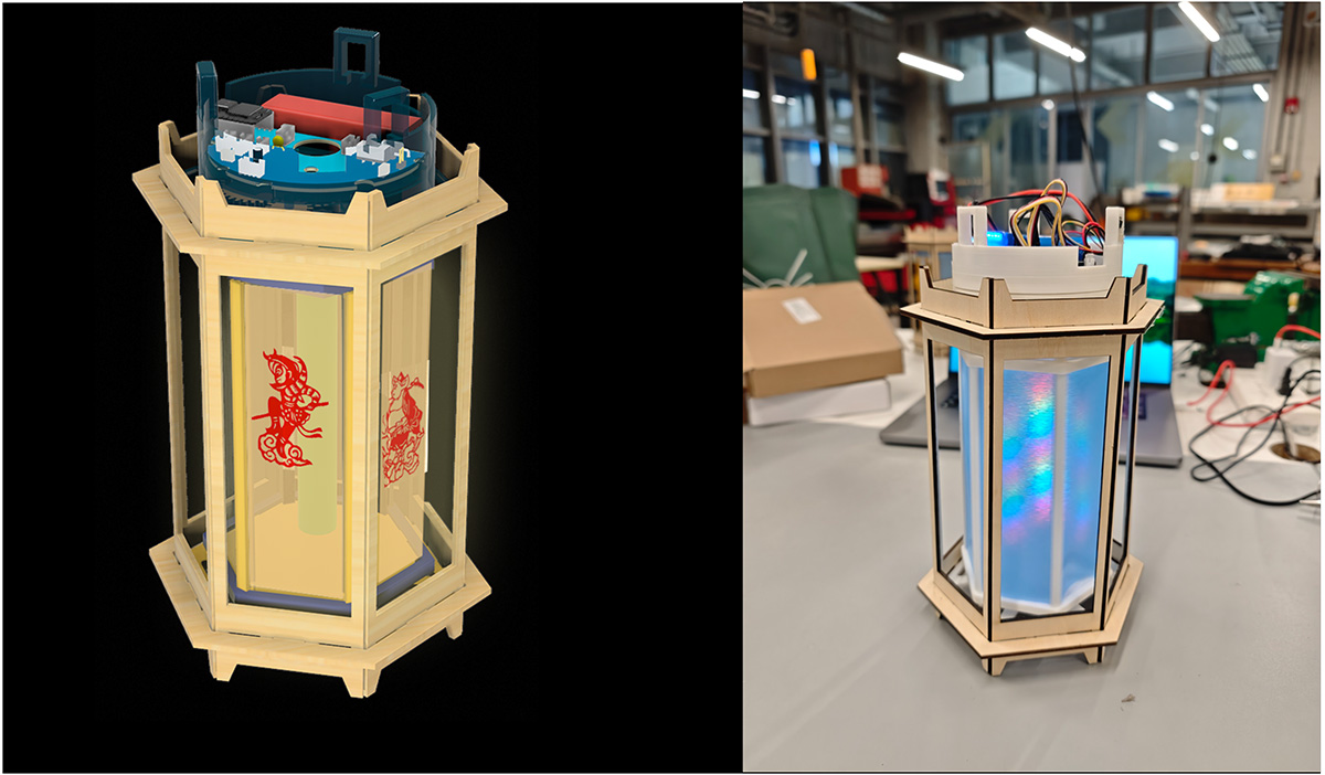
From design to finished product
Quality Control and Testing
Each manufacturing link has corresponding quality control standards:
Mechanical Parts:
- Dimensional accuracy: ±0.1mm
- Surface quality: No obvious layer lines
- Assembly clearance: 0.2-0.5mm
Electronic Parts:
- Soldering quality: Visual inspection + continuity testing
- Functional testing: Module-by-module step-by-step verification
- Complete machine testing: Long-term stability verification
Project Evaluation Standards
Technical Implementation Assessment
I conducted an overall evaluation of the project
Core Function Verification (Total 40 points):
- ✅ Motor and gear transmission control: 7/10 points (rotating cage rotation quite stable after gear improvement)
- ⚠️ Gesture recognition system: 7/10 points (sometimes fails)
- ✅ LED light effect control: 8/10 points
- ✅ Wireless connection function: 8/10 points
User Experience (Total 25 points):
- 🔄 Interaction response speed: 8/10 points (continuously optimizing)
- ✅ Interface aesthetics and usability: 6/10 points
- ✅ Overall completion quality: 4/5 points
Technical Innovation (Total 25 points):
- ✅ System complexity: 6/10 points
- ✅ Manufacturing process difficulty: 7/10 points
- ✅ Creative uniqueness: 3/5 points
Documentation Completeness (Total 10 points):
- ✅ Detailed process recording: 4/5 points
- ✅ Complete open-source materials: 4/5 points
Project Total Score: 72/100 points
Project Significance and Value
Digital Expression of Cultural Heritage
This project is not just a technical showcase, but also a new attempt at cultural inheritance. As a carrier of traditional Chinese culture, how can the revolving lantern maintain its cultural core while bursting with new vitality in the digital age? The Magical Revolving Lantern provides a possible answer.
Preservation of Traditional Elements:
- Classic hexagonal shape
- Core concept of rotation creating dynamic beauty
- Light and shadow changes creating poetic atmosphere
Empowerment by Modern Technology:
- Controllable rotation and light effects
- Intelligent interaction methods
- Networked connection capabilities
Practice of Open Source Spirit
All design files, code, and manufacturing tutorials for the project will be released as open source, hoping to:
- Provide complete reference cases for other Makers
- Promote digital innovation of traditional culture
- Facilitate knowledge sharing in the Fab Lab community
Open Source Content List:
- Complete 3D model files
- PCB design files (schematics + layout)
- Firmware source code
- Manufacturing tutorials and BOM list
- Video demonstrations and technical analysis
Reflection and Outlook
18-Week Growth Trajectory
Looking back at this 18-week project journey, the biggest gain was not mastering how many new technologies, but learning how to transform complex ideas into achievable solutions, and how to make reasonable trade-offs under time and resource constraints.
Technical Level Gains:
- Mastered complete digital manufacturing process chain
- Learned systematic engineering thinking
- Improved problem-solving abilities
Non-technical Growth:
- Project management and time planning abilities
- Team collaboration and communication skills
- Open source sharing awareness and habits
Future Improvement Directions
There are still many areas where this project can be improved:
Function Expansion:
- Add sound sensing for music rhythm effects
- Include temperature and humidity sensors to create smart ambient lighting
- Develop mobile APP for richer control options
Performance Optimization:
- More efficient power management system
- Faster gesture recognition algorithms
- More stable wireless communication protocols
Product Development Exploration:
- Modular design for user customization
- Further cost optimization to improve cost-effectiveness
- Build user community to promote creative sharing
Acknowledgments
The completion of this project wouldn't have been possible without the help of many people:
- Mentor Team: Pradnya Shindekar and Yu Jianfeng for their professional technical guidance and advice
- Seeed Studio: For financial support, with special thanks to Engineer Xu Guoqun for professional CNC operation guidance, and hardware engineer Qu Xiangnan for professional soldering guidance
- Chaihuo Makerspace: Provided comprehensive manufacturing equipment and environment
- Fab Lab Community: Rich open-source resources and experience sharing
- Family and Friends: Thanks to my wife for her care throughout the learning process
- Claude AI: Provided valuable suggestions in PCB design and technical solution selection
Conclusion
The Magical Revolving Lantern is not just my Fab Academy final project, but also my exploration of the fusion of traditional culture with modern technology. In this rapidly changing era, how can traditional culture burst with new vitality? How can technology be more humane and caring?
Perhaps the answer lies in each of our small creations, in every bold attempt, in every open-source sharing.
I hope this small Magical Revolving Lantern can ignite more people's passion for creation, love for culture, and longing for the future.