Week 9 Individual Assignment 2: Adding a Gesture Sensor to the XIAO ESP32C3
Project Introduction
The main goal of this week's individual project is to add a sensor to your designed microcontroller board and read data from it. For my final project idea "Smart Fantasy Lantern", I need to implement gesture control, as shown in the image below.
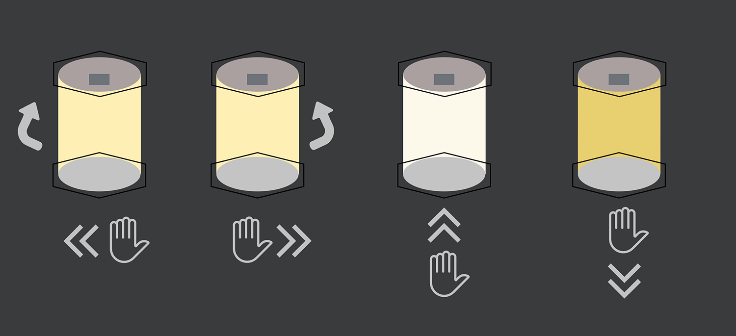
In my final project "Smart Fantasy Lantern," the gesture control system will serve as the main user interface, implementing the following control functions:
- Left/right gestures: Control the lantern's rotation direction (clockwise/counterclockwise)
- Up/down gestures: Adjust light brightness (increase/decrease)
So I searched for some gesture sensors on Taobao and found one that I wanted to try: Ultra-mini gesture sensor for motion direction and RGB color recognition module for Arduino and Raspberry Pi.
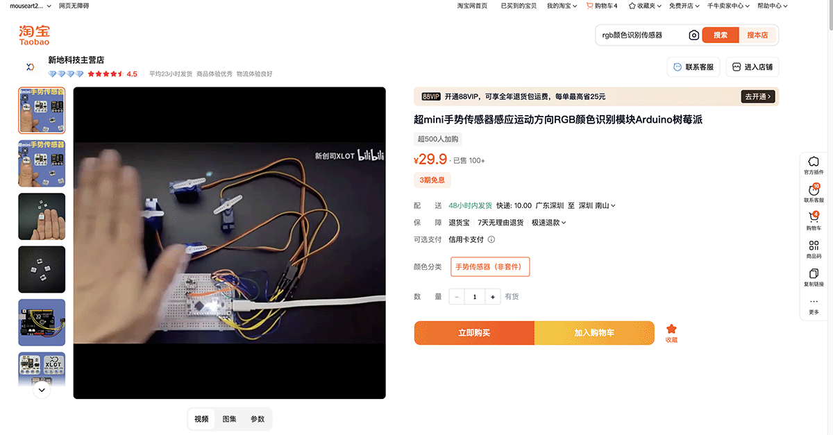
Taobao's Xindi Technology store offers an ultra-mini gesture sensor, priced at 29.9 RMB
I purchased 3 of them, partly for this Week 9 individual assignment and partly to see if they could be used in my final project.
For this week's assignment, I've set several specific goals including:
- Understanding the working principles of the gesture sensor
- Designing the sensor circuit and connecting it to the XIAO ESP32C3
- Writing code to test the gesture recognition functionality
- Documenting the entire design, manufacturing, and testing process
- Demonstrating the input device's working principle and its application scenario in the final project
Understanding the Working Principles of the Gesture Sensor
The "ultra-mini gesture sensor" product I purchased has been appropriately modularized by Xindi Technology (or XLOT brand), making the APDS-9960 chip easy to integrate with various microcontrollers (such as the XIAO development board). The image on the left shows the sensor I purchased, which came with various connection cables, and on the right is my current development board.
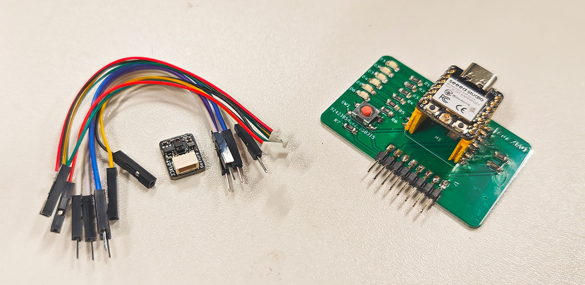
XLOT APDS-9960 module (left) compared with my XIAO development board
I'll now focus on studying the APDS-9960 gesture sensor, which is a multifunctional integrated sensor designed and manufactured by Broadcom. This sensor has been adopted by Xindi Technology (XLOT) and packaged as a module convenient for DIY electronics enthusiasts.
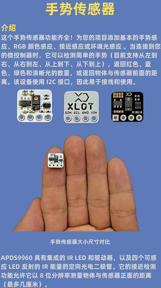
The Taobao supplier's documentation is quite basic, with only simple image explanations
APDS-9960 Introduction
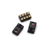
APDS-9960 sensor on the module
The APDS-9960 is a multifunctional sensor that integrates gesture detection, proximity sensing, ambient light sensing, and RGB color sensing. I found the APDS-9960 Data Sheet on its official website. Its features include:
- Gesture Detection: Can recognize gestures in four directions - up, down, left, and right
- Proximity Detection: Can measure the distance between an object and the sensor
- Ambient Light and RGB Color Sensing: Can measure ambient light intensity and RGB color components
- I2C Communication Interface: Standard I2C interface, compatible with 3.3V and 5V logic levels
- Integrated IR LED: Built-in infrared LED light source for gesture and proximity detection
Physical Structure
The APDS-9960 sensor has a compact package size (approximately 3.94mm×2.36mm×1.35mm) and contains the following core components:
- Infrared LED Light Source: Emits infrared light with a wavelength of 940nm
- Four Directional Photodiodes: Detect reflected infrared light from up, down, left, and right directions
- Filters: Include UV and IR filters to improve color sensing accuracy
- Integrated LED Driver Circuit: Controls the IR LED's pulse width and current intensity
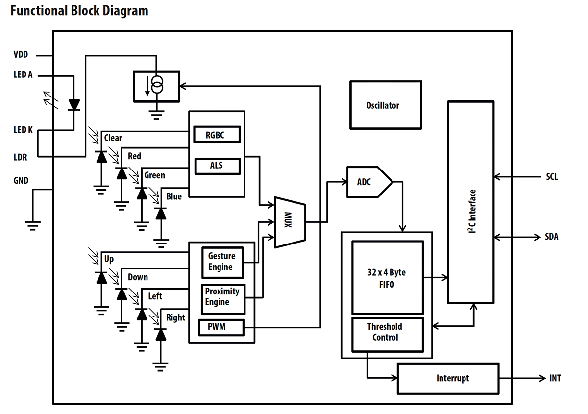
Functional block diagram from the APDS-9960 sensor Data Sheet
Working Principles
Gesture Detection Principle
The gesture detection functionality of the APDS-9960 is based on the principle of light reflection, with the following workflow:
- IR Light Emission: The built-in infrared LED emits pulsed IR light
- Gesture Reflection: When a user makes a gesture above the sensor, the IR light is reflected
- Directional Photodiode Reception: Four directional photodiodes receive the reflected light and convert it into electrical signals
- Signal Processing: The sensor's internal processor analyzes the signal intensity changes from the four photodiodes
- Gesture Recognition: Based on the timing and intensity changes of signals from different directional photodiodes, the gesture direction is recognized
The gesture recognition principle is based on motion detection:
- Left to Right Gesture: First activates the left photodiode, then the right
- Right to Left Gesture: First activates the right photodiode, then the left
- Top to Bottom Gesture: First activates the top photodiode, then the bottom
- Bottom to Top Gesture: First activates the bottom photodiode, then the top
By analyzing these signals over time, the sensor can recognize basic directional gestures. Theoretically, with complex algorithm processing, it could also recognize more complex gesture patterns.
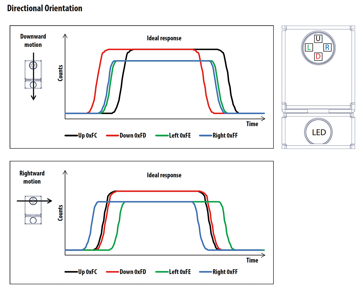
Directional positioning principle diagram from the APDS-9960 sensor Data Sheet
Proximity Detection Principle
Proximity detection uses the same IR LED and photodiodes but employs a different signal processing method:
- The IR LED emits infrared light
- An object reflects the infrared light
- The photodiodes detect the reflected light intensity
- The reflected light intensity is inversely proportional to distance, allowing the estimation of object distance by measuring reflected light intensity
The APDS-9960 sensor can measure object distances within approximately 10 centimeters, with an 8-bit resolution (0-255).
Ambient Light and Color Detection Principle
Ambient light and color sensing use dedicated photodiode arrays:
- The photodiodes have different color filters (red, green, blue, and clear) above them
- Four channels collect light intensity in specific wavelength ranges in parallel
- A built-in 16-bit ADC converts the photodiode signals into digital values
- These values can be used to calculate ambient light intensity and color components
Key Characteristics of the APDS-9960 Sensor
According to the datasheet, the APDS-9960 has the following technical characteristics:
| Parameter | Specification |
|---|---|
| Operating Voltage | 2.4V-3.6V |
| Communication Protocol | I²C (up to 400kHz) |
| Integrated LED Wavelength | 950nm |
| Gesture Detection Distance | Approximately 10-15cm |
| Proximity Detection Range | 0-255 (8-bit resolution) |
| Color Detection Resolution | 16-bit (per channel) |
| Integrated FIFO Buffer | 32×4 bytes (for gesture data) |
| Operating Temperature | -30°C to 85°C |
Sensor State Machine Workflow
The APDS-9960 implements an internal state machine to control the workflow of various functional units:
Workflow summary:
- Initialization: The sensor enters a low-power sleep state after power-up
- Wake-up: The internal oscillator is activated via I2C commands
- Function Enabling: Gesture, proximity, color/ambient light functions can be enabled individually
- Data Collection: Data is collected in a specific order according to enabled functions
- Interrupt Generation: Interrupts are generated when data exceeds thresholds or gestures are recognized
- Data Reading: The master controller reads data registers via I2C
- Return to Idle or Sleep: Returns to idle or sleep state after data processing is complete
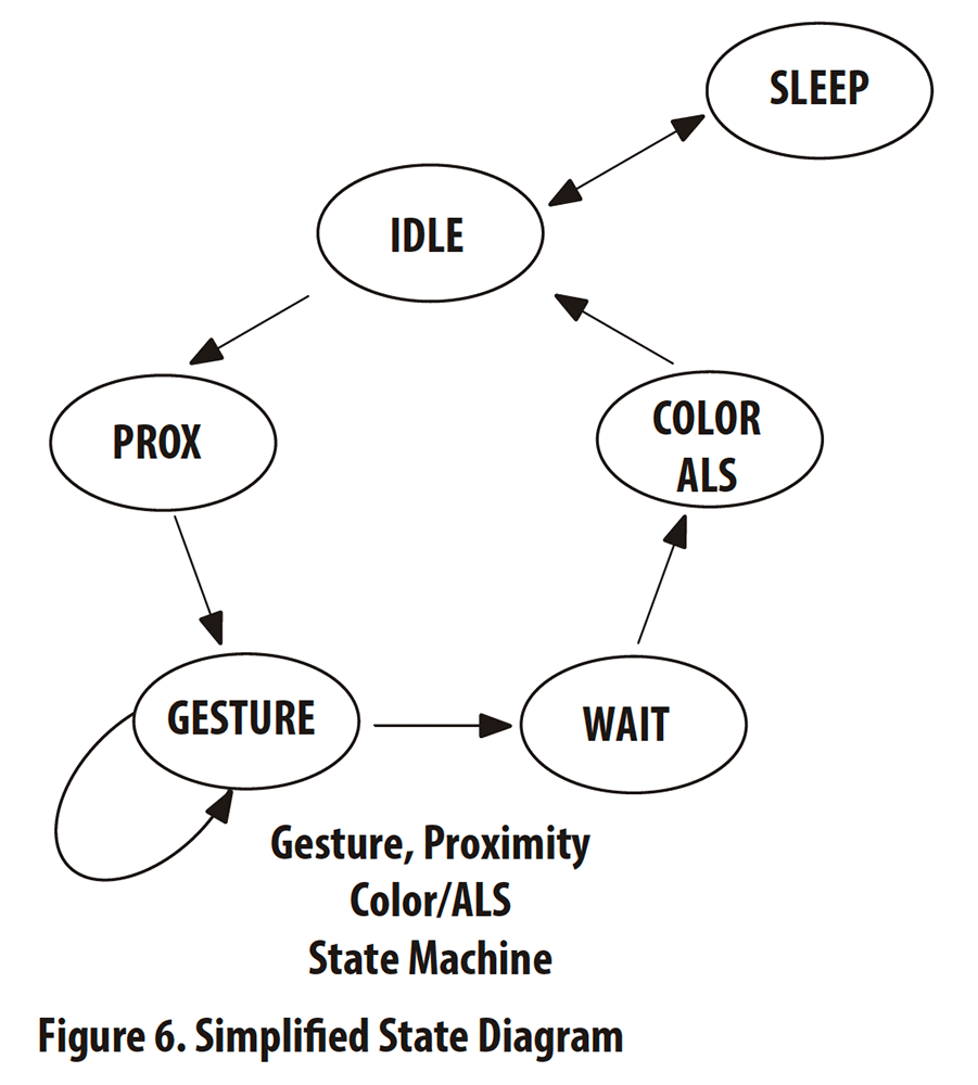
Simplified state diagram from the APDS-9960 sensor Data Sheet
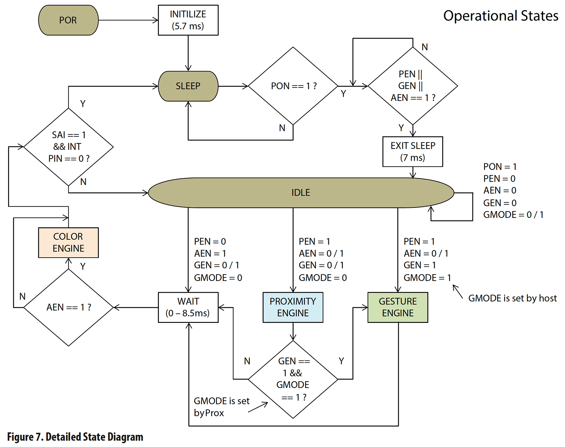
Detailed state diagram from the APDS-9960 sensor Data Sheet
Gesture Engine Data Flow
The data flow for gesture detection is as follows:
- Gesture Entry Condition: Enters the gesture state machine when the proximity value exceeds the set threshold
- Data Collection: Continuously measures signal strength in four directions
- FIFO Storage: Stores signal data from four directions (UDLR) in a 32×4 byte FIFO buffer
- Interrupt Generation: Generates an interrupt when the FIFO data amount reaches the threshold
- Gesture Recognition: The master controller reads FIFO data and processes it with the gesture algorithm
- Gesture Exit: Exits the gesture state when signal strength in all directions falls below the threshold
This design allows continuous monitoring of gestures while minimizing interference with the master controller.
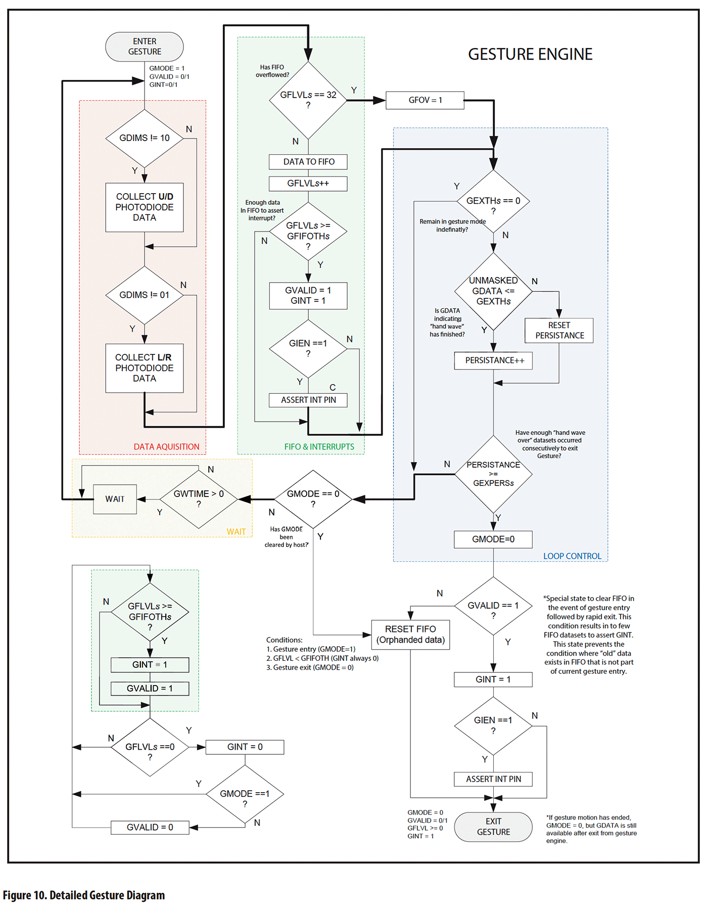
Detailed gesture operation flow chart from the APDS-9960 sensor Data Sheet
Interface Method with Microcontroller
The APDS-9960 communicates with microcontrollers via the I2C interface:
- Fixed I2C Address: 0x39
- Communication Rate: Supports up to 400kHz fast mode
- Interrupt Pin: Provides a dedicated interrupt output pin that can trigger the microcontroller's external interrupt
- Register Mapping: Configures sensor parameters and reads data through registers
The XLOT-designed module adds a level conversion circuit to the APDS-9960, making it compatible with both 3.3V and 5V logic levels, facilitating connection with various microcontrollers.
Designing the Sensor Circuit and Connecting It to the XIAO ESP32C3
Hardware Connection Scheme
The APDS-9960 gesture sensor uses the I2C communication protocol, making its connection to the XIAO ESP32C3 very simple and direct. The sensor requires only four pin connections, including power, ground, and two data lines for I2C communication.
I attached a 4-color wire connector to the gesture sensor and asked the supplier about the pin correspondence of the four colored wires. Red, black, yellow, and green represent VCC, GND, SDA, and SCL respectively.
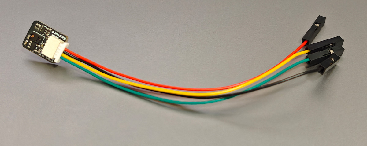
XLOT APDS-9960 module with the 4-color wire connector included with purchase. The female headers on the other end can be plugged directly into the XIAO's pin headers
Since my previously designed development board didn't expose D4 and D5, I first directly connected via pins to test the code and performance.
Connection Details
| APDS-9960 Pin | XIAO ESP32C3 Pin | Function |
|---|---|---|
| VCC | 5V | Power positive |
| GND | GND | Power ground |
| SDA | D4/GPIO6 | I2C data line |
| SCL | D5/GPIO7 | I2C clock line |
Wiring Diagram
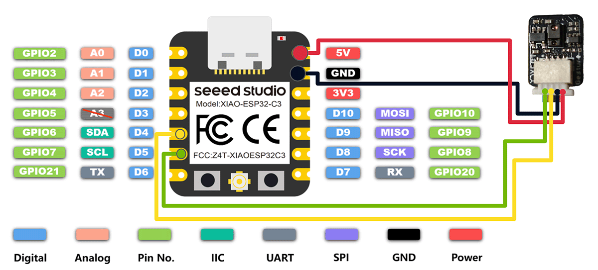
Wiring diagram of XIAO ESP32C3 and XLOT APDS-9960 module
Hardware Connection Considerations
- Power Selection: I communicated with the Taobao seller and was informed that the sensor module can operate within a 3V-5V voltage range, so I connected it to the 5V pin.
- I2C Bus Configuration: By default, the XIAO ESP32C3's I2C bus uses the D4(SDA) and D5(SCL) pins. Pull-up resistors are not required, as the XIAO ESP32C3 already has internal pull-up resistors.
- Sensor Placement: The placement of the gesture sensor is very important and should ensure:
- No obstacles within 5-10cm range above the sensor
- Sensor facing the user for convenient gesture operations
- Securely fixed to avoid movement that could cause misreading
- Connection Wire Length: Use the shortest possible connection wires, especially for I2C signal lines, to reduce signal interference. Recommended connection wire length should not exceed 20cm.
Actual Connection Implementation
Since the project is in the prototype stage, I used Dupont wires for temporary connection to connect the XLOT APDS-9960 module with the previously designed XIAO ESP32C3 extension board. The physical setup after connection is shown in the image below:
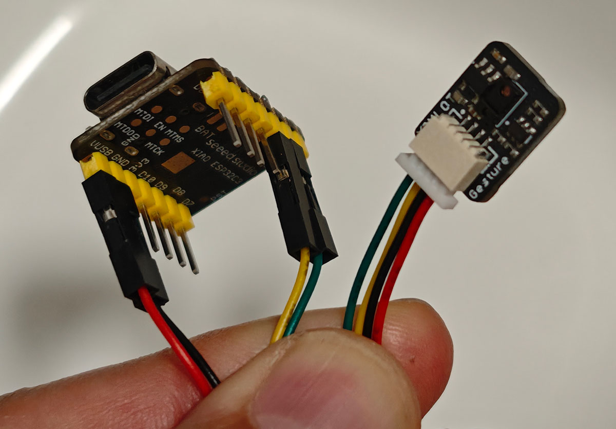
Connection effect of XIAO ESP32C3 and XLOT APDS-9960 module
For the final project, more reliable connection methods will be considered, such as soldering or using sturdy connectors, to ensure long-term stable operation of the system.
Sensor Placement Design
The placement of the sensor is critical for optimal gesture recognition. After several tests, I determined the following placement plan:
- Cardboard Box Mounting Method: I adopted a simple but practical method of fixing the gesture sensor to the inner wall of a cardboard box lid with tape. This approach has several obvious advantages:
- Facilitates keeping the sensor in an upright position
- Allows for easy adjustment of the sensor angle
- Provides a lightweight yet stable support structure
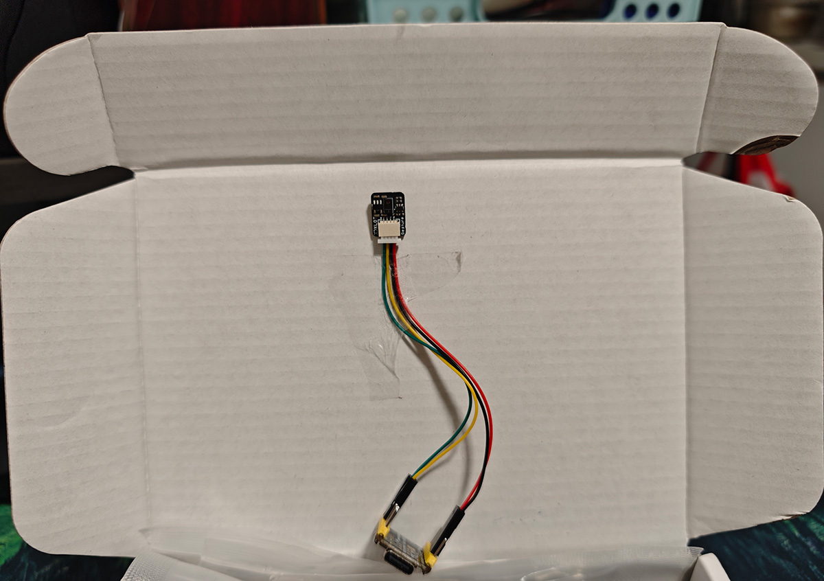
XLOT APDS-9960 module fixed to the inner wall of a cardboard box lid with tape
- Height Positioning: The sensor surface is about 3cm from the base, making it convenient for users to perform gestures 5-10cm above the device.
- Angle Adjustment: The sensor is slightly tilted upward by about 15 degrees, making it easier to capture user hand movements. This tilt angle was easily achieved by the way the tape secured it to the inner wall of the box lid.
- Light Shielding Design: The cardboard box itself provides some light shielding effect. I only kept a sufficient opening on top of the box for gesture operations. This simple light shielding design greatly improved recognition accuracy in strong light environments.
- Position Marking: Simple markers were added to the outside of the box, indicating the optimal position for users to perform gestures.
This method of using a cardboard box as a support is not only low-cost but also convenient for assembly and disassembly, making it very suitable for quick testing and adjustment during the prototype development stage.
Programming and Testing Gesture Recognition Functionality
Development Environment Setup
The development environment is based on Arduino IDE, with the following main steps:
- Install XIAO ESP32C3 Development Board Support:
- Add Seeed Studio XIAO development board support in Arduino IDE
- Select "XIAO_ESP32C3" as the target development board
- Install XLOT_APDS9960 Library:
- The seller provides the required library file: XLOT_Gesture_Sensor_update.zip
- Copy the downloaded XLOT_Gesture_Sensor library to the Arduino library folder
- Test Environment Preparation:
- Set the serial monitor baud rate to 115200
- Prepare the test environment, ensuring stable lighting conditions
Test Program Code
The seller first provided an I2C test program to detect the 0x39 sensor device.
#include <Wire.h>

void setup() {
  Wire.begin(6,7);        // Initialize I2C bus//17,16   21 22
  Serial.begin(115200);  // Initialize serial port
  while (!Serial);     // Wait for serial port to open
}

void loop() {
  byte error, address;
  int devices = 0;

  Serial.println("Scanning...");

  for (address = 1; address < 127; address++ ) {
    Wire.beginTransmission(address);
    error = Wire.endTransmission();

    if (error == 0) {
      Serial.print("I2C device found at address 0x");
      if (address<16) {
        Serial.print("0");
      }
      Serial.print(address,HEX);
      Serial.println("  !");
      devices++;
    }
    else if (error==4) {
      Serial.print("Unknown error at address 0x");
      if (address<16) {
        Serial.print("0");
      }
      Serial.println(address,HEX);
    }
  }
  if (devices == 0) {
    Serial.println("No I2C devices found\n");
  }
  else {
    Serial.println("done\n");
  }
  // delay(5000);  // Perform I2C scan every 5 seconds
}When running the test program, if the wiring is correct, you will see the following screen.
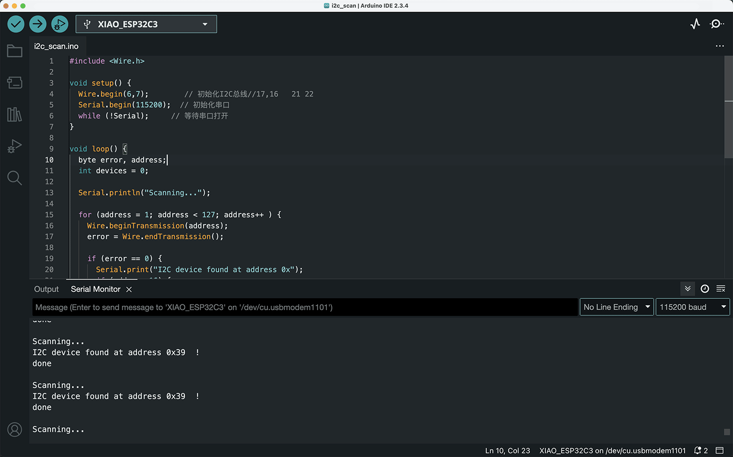
Scan indicates I2C device found at address 0x39
Scanning...
I2C device found at address 0x39  !
doneThen I ran the gesture recognition test program provided by the Taobao seller, which can recognize up, down, left, and right gestures captured by the APDS-9960 sensor, and provide feedback through LED and serial output:
#include <Wire.h>

#include "XLOT_APDS9960AD.h"
XLOT_APDS9960AD apds;

// the setup function runs once when you press reset or power the board
void setup() {
  Serial.begin(115200);
  Wire.begin(6, 7);

  if(!apds.begin()){
    Serial.println("failed to initialize device! Please check your wiring.");
  }
  else Serial.println("Device initialized!");

  //gesture mode will be entered once proximity mode senses something close
  apds.enableProximity(true);
  apds.enableGesture(true);
  apds.setProxGain(APDS9960_PGAIN_8X);
  apds.setGestureGain(APDS9960_PGAIN_8X);
  apds.setGestureGain(APDS9960_AGAIN_64X);
  apds.setGestureGain(APDS9960_GGAIN_8);
}

// the loop function runs over and over again forever
void loop() {
  //read a gesture from the device
    uint8_t gesture = apds.readGesture();
    if(gesture == APDS9960_DOWN) Serial.println("v");
    if(gesture == APDS9960_UP) Serial.println("^");
    if(gesture == APDS9960_LEFT) Serial.println("<");
    if(gesture == APDS9960_RIGHT) Serial.println(">");
}When running the program, you can see the gesture direction indicators output in the serial monitor, as shown below.
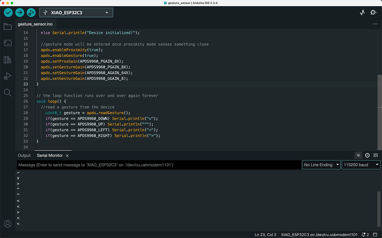
Gesture direction indicators output in the serial monitor
The actual operation effect video is shown below.
 Lei Feng Fab Academy 2025