Week 4 Individual Assignment: Embedded Development Practice with XIAO MG24
For my final project, the Magical Shadow Theater, I decided to try the newly released XIAO MG24 Sense. This thumb-sized development board integrates an ultra-low-power wireless development board based on the Silicon Labs EFR32MG24 SoC, featuring a high-performance 78MHz ARM Cortex®-M33 core, onboard analog microphone, and six-axis IMU sensor. These features open up many possibilities for my Magical Shadow Theater project. And it costs less than $11.
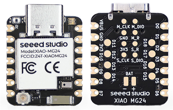
Front and back views of XIAO MG24 Sense
I. Microcontroller Datasheet Analysis
The datasheet provided by Seeed Studio is the EFR32MG24 Series Wireless SoC datasheet, published by Silicon Labs, primarily targeting IoT wireless connectivity applications. The document details the product's core features, such as the 32-bit ARM Cortex-M33 processor, 2.4GHz high-performance wireless transceiver, low-power design, and security features (including Secure Vault and AI/ML hardware accelerator). Additionally, the document covers the product's feature list, ordering information, system architecture, radio design, various peripheral interfaces (such as GPIO, USART, I2C, etc.), clock and power management, pin definitions, and packaging specifications, providing engineers with complete technical parameters and application guidance to help them make optimal choices in wireless communication and IoT device design.
The first page of the manual shows the overall architecture diagram of the EFR32MG24 chip, as shown below.
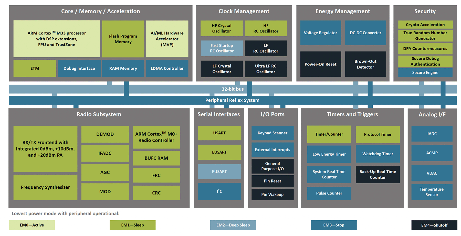
Overall architecture diagram of the EFR32MG24 chip
Its core components can be divided into the following main parts:
Core System Section (Upper Left)
- Features ARM Cortex-M33 processor with DSP extensions, FPU floating-point unit, and TrustZone security features
- Includes Flash program memory, RAM memory, and LDMA direct memory access controller
- Integrates AI/ML hardware accelerator (MVP) for machine learning acceleration
- Provides ETM and debug interface for development debugging
Clock Management System (Upper Middle)
Offers multiple clock source options:
- High-frequency crystal and RC oscillator
- Fast-start RC oscillator
- Low-frequency crystal and RC oscillator
- Ultra-low frequency RC oscillator
Energy Management System (Upper Right)
- Voltage regulator
- DC-DC converter
- Power-on reset
- Under-voltage detector
Security Features (Far Right)
- Encryption accelerator
- True random number generator
- DPA protection measures
- Secure debug authentication
- Security engine
Bottom Peripheral System
- Radio electronics system: includes transmit/receive front end, digital demodulation, etc.
- Serial interfaces: USART, EUSART, and other communication interfaces
- I/O ports: supports keyboard scanning, external interrupts, etc.
- Timer system: various timers and counters
- Analog interface: ADC, comparators, and other analog peripherals
The chip supports 5 power consumption modes (bottom):
EM0 (Active) → EM1 (Sleep) → EM2 (Deep Sleep) → EM3 (Stop) → EM4 (Shutoff), with power consumption decreasing progressively.
All these modules are interconnected through a 32-bit bus and peripheral reflection system, forming a complete low-power wireless system-on-chip solution.
I focused on understanding the following sections in detail.
Chip Overview
The core of the EFR32MG24 series chips is the ARM® Cortex®-M33 processor, which can reach a maximum operating frequency of 78 MHz. This processor features digital signal processing (DSP) instruction set, floating-point unit (FPU), and TrustZone security technology, ensuring efficient data processing capabilities and system security. The chip includes up to 1536 kB of flash memory and 256 kB of RAM, providing ample storage space for complex IoT applications.
Wireless Communication Capabilities
The wireless module of this chip series supports the 2.4 GHz band and features a high-performance radio transceiver, supporting various wireless protocols including Matter, OpenThread, Zigbee, and Bluetooth Low Energy. The radio portion of the chip offers high sensitivity and high output power, ensuring stable communication in various environments. For example, its receiving sensitivity can reach -105.4 dBm (250 kbps O-QPSK), while the output power can reach up to +19.5 dBm.
Low Power Design
The EFR32MG24 series chips particularly emphasize low power consumption in their design, featuring multiple low-power modes to suit different application scenarios. In EM0 mode, the chip's current consumption is only 33.4 µA/MHz, while in EM4 mode, current consumption can be as low as 0.25 µA. This low-power characteristic makes the chip very suitable for battery-powered devices, extending device usage life.
Security Features
Security is a major highlight of the EFR32MG24 series chips. The chip includes a built-in Secure Vault security module, providing features such as hardware encryption accelerator, true random number generator (TRNG), secure boot, and secure debug capabilities. These security features ensure device protection against both remote and local network attacks.
Peripheral Interfaces and Functions
The EFR32MG24 series chips provide rich peripheral interfaces, including GPIO, USART, EUSART, I2C, timers, etc., supporting various communication protocols and functions. For example, the chip's GPIO pins have multiple functions, including input, output, open-drain configuration, and glitch filtering. Additionally, the chip integrates analog comparators (ACMP), digital-to-analog converters (VDAC), and analog-to-digital converters (IADC), meeting various analog signal processing needs.
XIAO MG24 Sense Wiki Documentation
The XIAO MG24 Sense Wiki documentation provided by Seeed Studio helps users quickly understand how to use the product.
The XIAO MG24 Sense functional module diagram from the Wiki documentation is shown below:
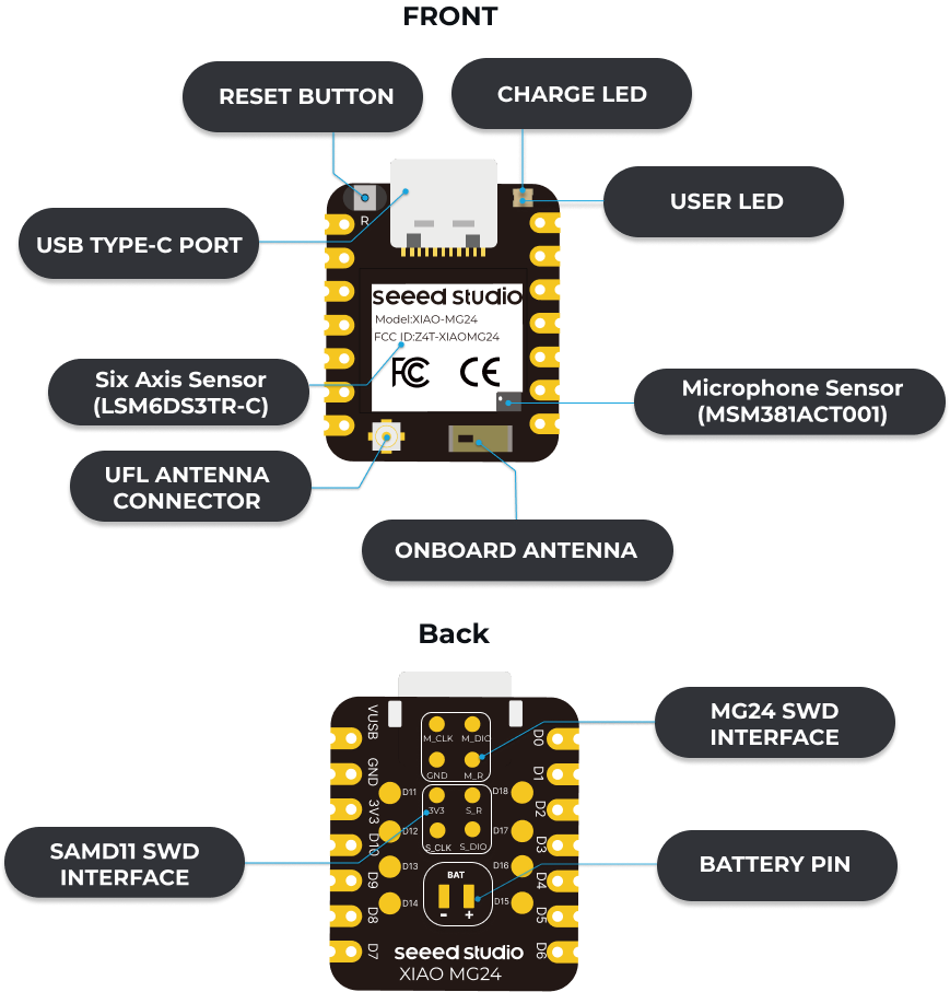
XIAO MG24 Sense indication diagram
The pin diagram of XIAO MG24 Sense is shown below:
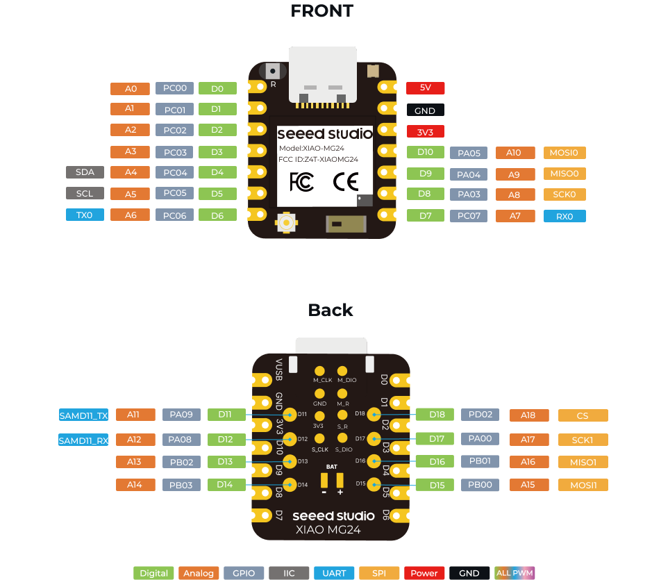
XIAO MG24(Sense) Pin List
XIAO MG24 Sense Basic Function Testing
Since this board is also relatively new to me, I want to test its basic functions, typically starting with Blink (making the board's USER LED flash) to understand and test the entire development environment's availability. I also want to explore the onboard six-axis accelerometer to see how to read acceleration data to the serial monitor.
XIAO MG24 Sense Blink Tutorial
The XIAO MG24 Sense Wiki documentation provides a Blink tutorial. I've reorganized this process according to my operational habits.
I. Hardware and Software Preparation
1. Hardware Requirements
- XIAO MG24 Sense development board × 1
- USB Type-C data cable × 1
- Computer × 1
2. Software Requirements
- Arduino IDE: Ensure you have downloaded and installed the latest version (v2.0 or above recommended).
II. Setting Up Board Support
1. Open Arduino IDE
Launch Arduino IDE and ensure the software is properly installed.
2. Add Board Support
- Step 1: Open Board Manager
Click File → Preferences, and in the Additional Boards Manager URLs field, paste the following URL:
https://siliconlabs.github.io/arduino/package_arduinosilabs_index.json If you frequently program multiple development boards, you can click the  icon next to the URL field. In the popup window, add the board manager URL at the bottom, as shown in the image below.
Click OK to save the settings.
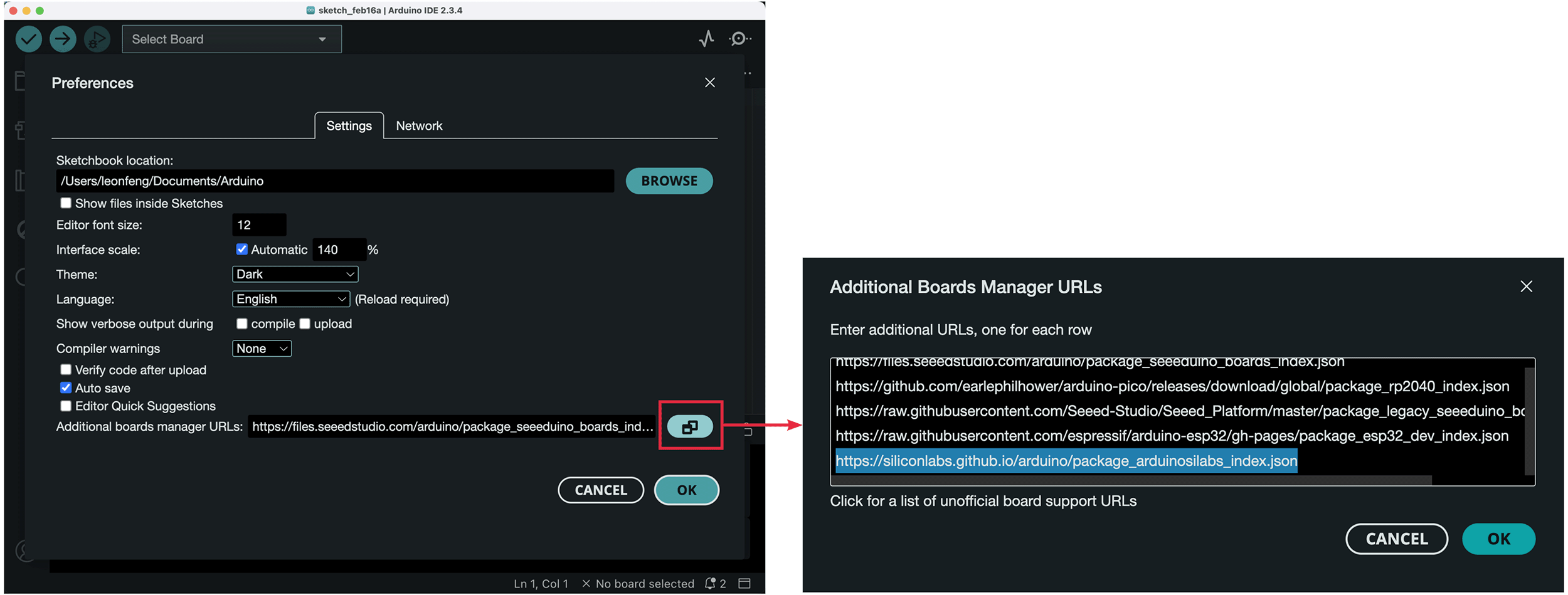
Adding board support in Arduino IDE
- Step 2: Install Board Package
- Click
Tools→Board→Boards Manager - Enter XIAO MG24 in the search box
- Find Arduino Silicon Labs Boards by Silicon Labs, click the
Installbutton to install, as shown below - Close the board manager after installation completes
- Click
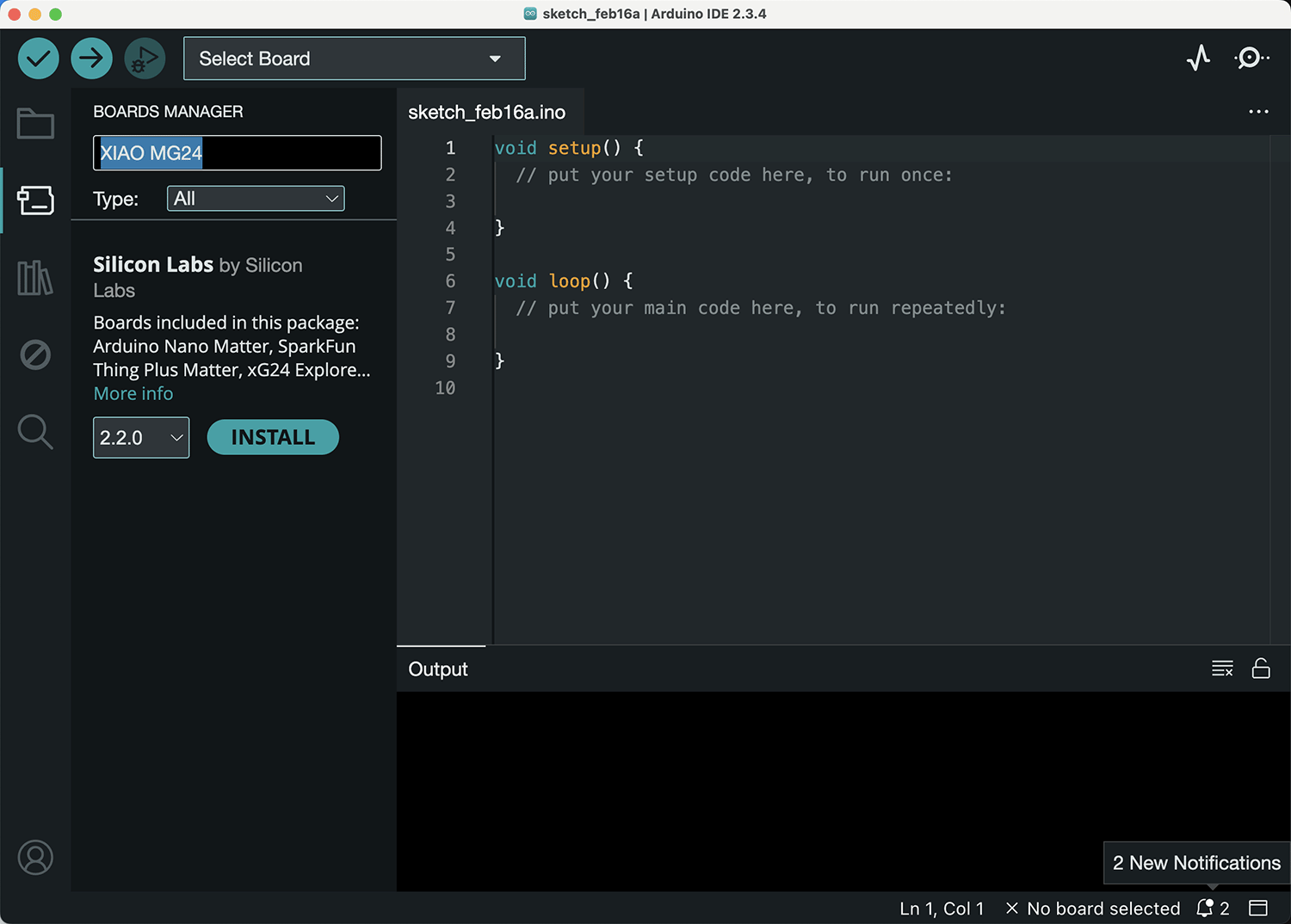
After successfully adding board support, search for XIAO MG24 in the board manager to find the installation package
3. Select Board
- Click:
Tools→Board→Silicon Labs Boards→XIAO MG24. When you connect the XIAO MG24 to your computer via Type-C, it will automatically select the XIAO MG24 board, as shown below.
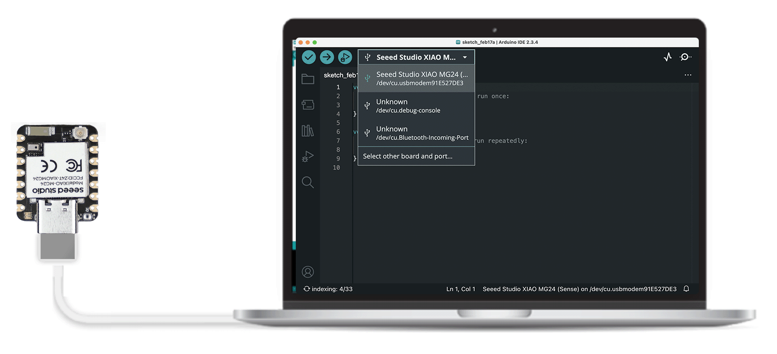
After successful package installation, connecting XIAO MG24 to the computer will automatically detect and select the XIAO MG24 board in Arduino IDE
III. Compile and Upload Blink Code
1. Open Blink Example Code
- Click:
File→Examples→01.Basics→Blink. The path is shown in the image below.
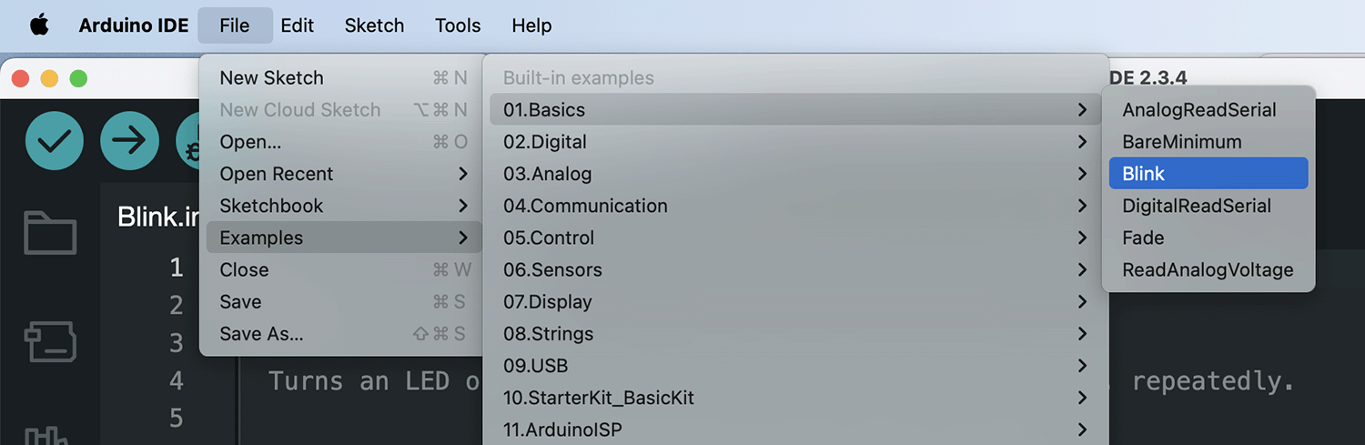
Path to open the Blink example program
The Blink program is as follows:
/*
  Blink

  Turns an LED on for one second, then off for one second, repeatedly.

  Most Arduinos have an on-board LED you can control. On the UNO, MEGA and ZERO
  it is attached to digital pin 13, on MKR1000 on pin 6. LED_BUILTIN is set to
  the correct LED pin independent of which board is used.
  If you want to know what pin the on-board LED is connected to on your Arduino
  model, check the Technical Specs of your board at:
  https://www.arduino.cc/en/Main/Products

  modified 8 May 2014
  by Scott Fitzgerald
  modified 2 Sep 2016
  by Arturo Guadalupi
  modified 8 Sep 2016
  by Colby Newman

  This example code is in the public domain.

  https://www.arduino.cc/en/Tutorial/BuiltInExamples/Blink
*/

// the setup function runs once when you press reset or power the board
void setup() {
  // initialize digital pin LED_BUILTIN as an output.
  pinMode(LED_BUILTIN, OUTPUT);
}

// the loop function runs over and over again forever
void loop() {
  digitalWrite(LED_BUILTIN, HIGH);  // turn the LED on (HIGH is the voltage level)
  delay(1000);                      // wait for a second
  digitalWrite(LED_BUILTIN, LOW);   // turn the LED off by making the voltage LOW
  delay(1000);                      // wait for a second
}2. Configure Port
- Ensure XIAO MG24 Sense is connected to your computer via USB Type-C cable.
- Click:
Tools→Port, select the port corresponding to XIAO MG24 Sense. Verify if the connection port is correct; if not, manually select it. On Windows systems, serial ports are displayed as "COM+number". On macOS or Linux systems, port names are typically "/dev/tty.usbmodem+number" or "/dev/cu.usbmodem+number".
3. Upload Code
- Click the

Uploadbutton (arrow icon on the right) or pressCtrl+Uto upload the code to XIAO MG24 Sense.
IV. Observe Results
- After successful upload, the
LED indicatoron the XIAO MG24 Sense board will start blinking, typically with a 1-second cycle. If you see the indicator blinking, it means you've successfully lit it up!
XIAO MG24 Sense Blink effect
- If you don't see the indicator blinking, check the following:
- Ensure the board is properly connected to the computer and the correct port is selected.
- Ensure the correct board support package is installed.
- Try uploading the code again.
XIAO MG24 Sense IMU Testing Tutorial
Professor Marcelo Rovai introduced IMU testing for a similar development board, the Seeed Studio XIAO nRF52840 Sense, in his Anomaly Detection & Motion Classification documentation, and provided a test code: https://github.com/Mjrovai/Seeed-XIAO-BLE-Sense/blob/main/xiao_test_IMU/xiao_test_IMU.ino.
Modifying the IMU Test Program
This code isn't suitable for the XIAO MG24 Sense's IMU for the following reasons:
IMU Model Differences:
- XIAO nRF52840 Sense uses the LSM9DS1 sensor
- XIAO MG24 Sense uses the LSM6DS3TR-C sensor
- Although both sensors belong to the LSM series, they have different hardware characteristics and interfaces
Software Library Differences:
- XIAO nRF52840 Sense uses the Seeed Arduino LSM9DS1 library
- XIAO MG24 Sense needs the Seeed_Arduino_LSM6DS3 library
- The two libraries have different API interfaces and initialization methods
Functional Support Range:
- LSM9DS1 supports accelerometer, gyroscope, and temperature measurement
- LSM6DS3TR-C mainly supports accelerometer and gyroscope functions
- Therefore, temperature-related test code needs to be removed
Based on these differences, I modified the test program as follows:
#include "LSM6DS3.h"
#include "Wire.h"

LSM6DS3 myIMU(I2C_MODE, 0x6A);  //I2C device address 0x6A

char cmd = ' ';  // Use a single character to store commands

void setup() {
  Wire.begin();
  Serial.begin(115200);
  delay(1000);

  if (myIMU.begin() != 0) {
    Serial.println("Device error");
  } else {
    Serial.println("Device OK!");
  }

  Serial.println("\nAvailable commands:");
  Serial.println("a - display accelerometer readings");
  Serial.println("g - display gyroscope readings");
  Serial.println("s - stop readings");
}

void loop() {
  if (Serial.available()) {
    cmd = Serial.read();
  }

  if (cmd == 'a') {
    // Accelerometer data
    float x = myIMU.readFloatAccelX();
    float y = myIMU.readFloatAccelY();
    float z = myIMU.readFloatAccelZ();
    Serial.print(x);
    Serial.print("\t");  // Use tab for separation
    Serial.print(y);
    Serial.print("\t");
    Serial.println(z);
  }
  else if (cmd == 'g') {
    // Gyroscope data
    float x = myIMU.readFloatGyroX();
    float y = myIMU.readFloatGyroY();
    float z = myIMU.readFloatGyroZ();
    Serial.print(x);
    Serial.print("\t");
    Serial.print(y);
    Serial.print("\t");
    Serial.println(z);
  }
  else if (cmd == 's') {
    cmd = ' ';  // Stop output
  }

  delay(100);  // 100ms sampling interval
}Installing the Seeed_Arduino_LSM6DS3 Library
To run the test program above, you need to install the Seeed_Arduino_LSM6DS3 library. There are two methods to install the library:
- Install via Arduino IDE Library Manager:
- Open Arduino IDE
- Click: Tools -> Manage Libraries
- Type "Seeed LSM6DS3" in the search box
- Find "Seeed Arduino LSM6DS3" library
- Click "Install" button
Below shows the status after successful installation.
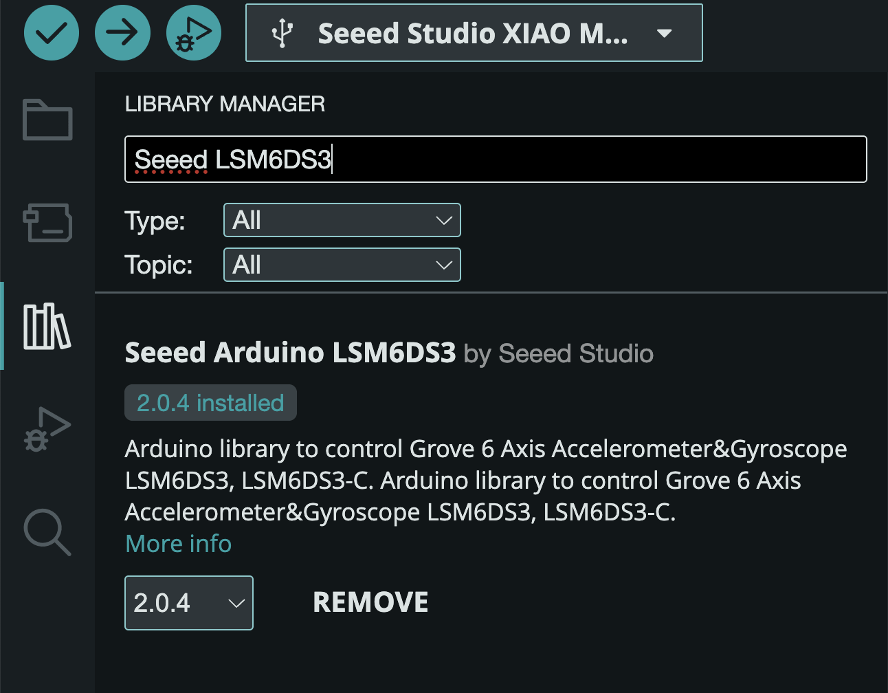
Searching and installing Seeed LSM6DS3 library through library manager
- Install via GitHub Download:
- Visit https://github.com/Seeed-Studio/Seeed_Arduino_LSM6DS3
- Click the "Code" button, select "Download ZIP", as shown below
- In Arduino IDE
- Click: Sketch -> Include Library -> Add .ZIP Library
- Select the downloaded ZIP file
- Wait for installation to complete
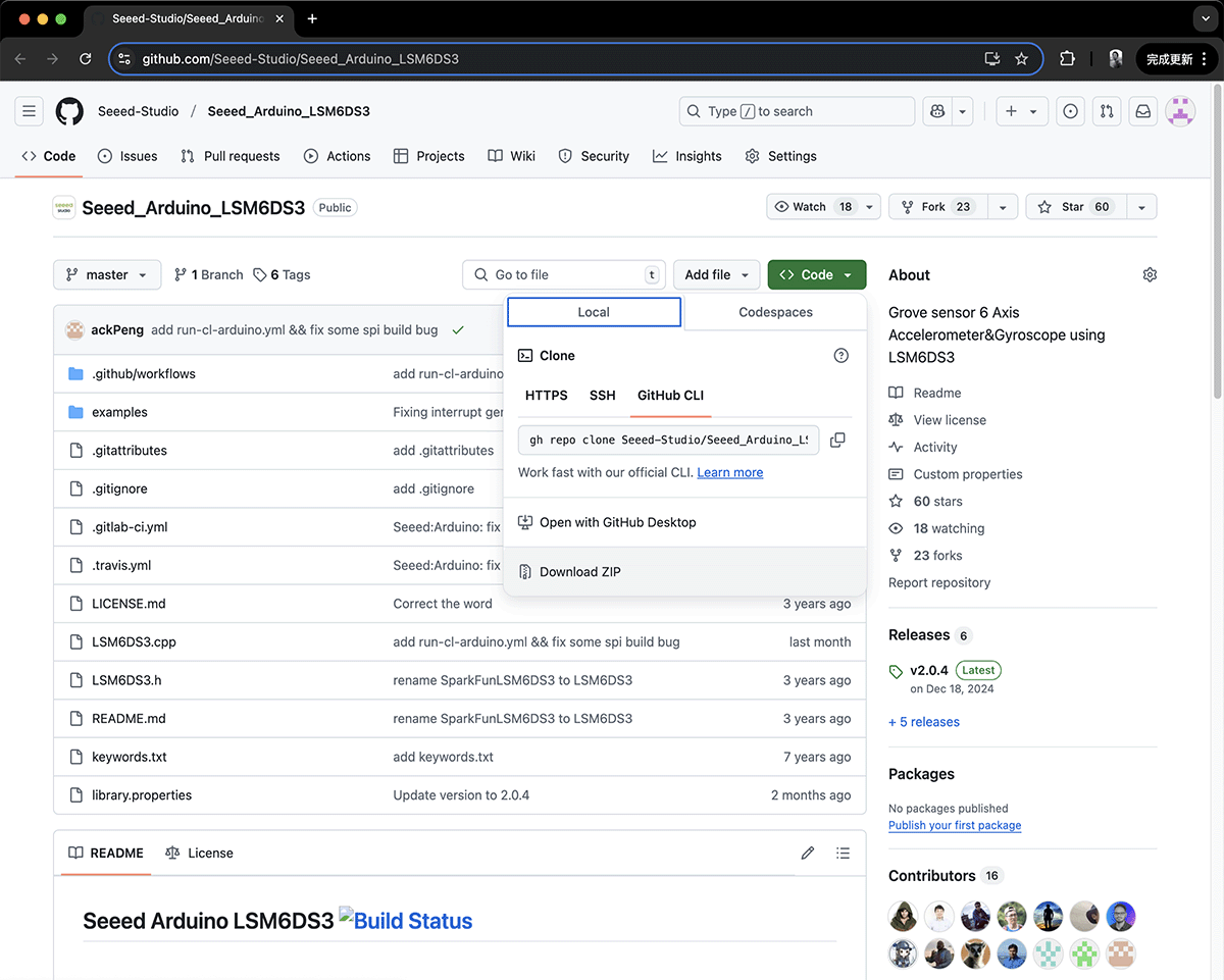
Downloading ZIP library through Github
After installation, you can:
- View example code through: File -> Examples -> Seeed_Arduino_LSM6DS3
- Use
#include "LSM6DS3.h"in your code to include the library
Note: You need to restart Arduino IDE after installing the library to ensure it's properly loaded.
Uploading IMU Test Program and Observing Results
After successfully installing the required library, upload the IMU test code in Arduino IDE, open the Serial Monitor, set the baud rate to 115200, and you'll see the prompt message shown below.
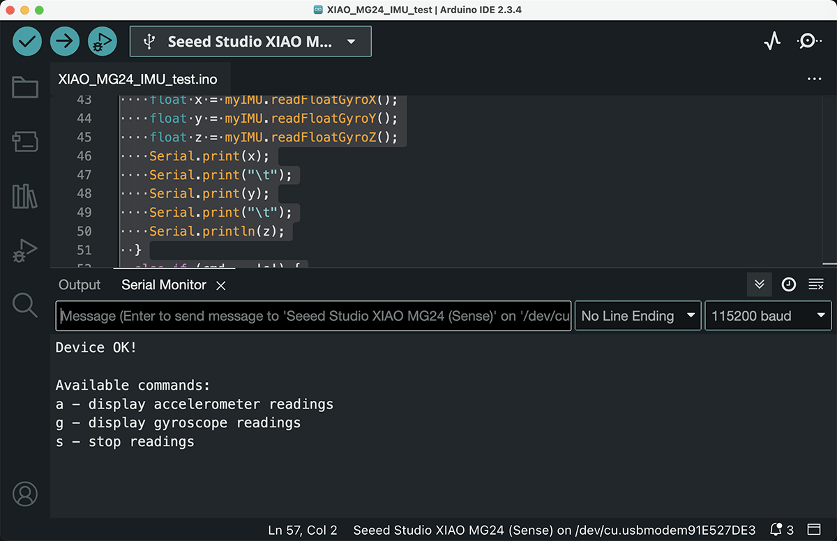
Running the IMU test program shows command prompts, waiting for input
Enter commands according to the prompts:
- Enter 'a' to display accelerometer data
- Enter 'g' to display gyroscope data
- Enter 's' to stop data display
Entering "a" will show continuous output of acceleration data from all 3 axes. Open the Serial Plotter, as shown below, to see the acceleration value curves for all 3 axes.
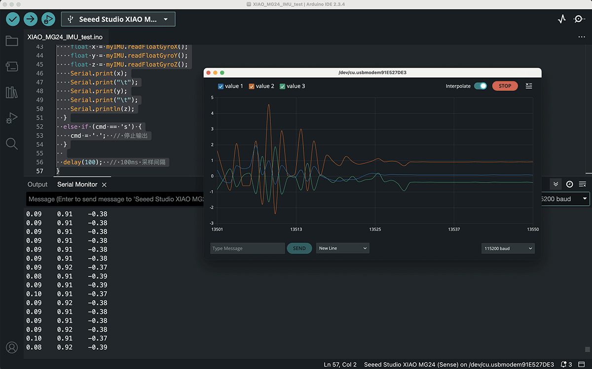
Opening Serial Plotter in Arduino
Now when we shake the XIAO MG24, we can see the Serial Plotter showing the acceleration changes across all 3 axes.
Arduino IDE's Serial Plotter showing the 3-axis acceleration change curves when shaking the XIAO MG24's IMU
For more detailed tutorial documentation, visit: https://wiki.seeedstudio.com/xiao_mg24_sense_built_in_sensor/
Simulating XIAO MG24 Programs on Wokwi
II. Simulation Environment Setup
Creating a Wokwi Project
- Visit the Wokwi online simulation platform
- Click on "ESP32"
- You can find "XIAO ESP32-C3" in the "Starter Templates" section
- As shown below, click on "XIAO ESP32-C3" to start from the sample project
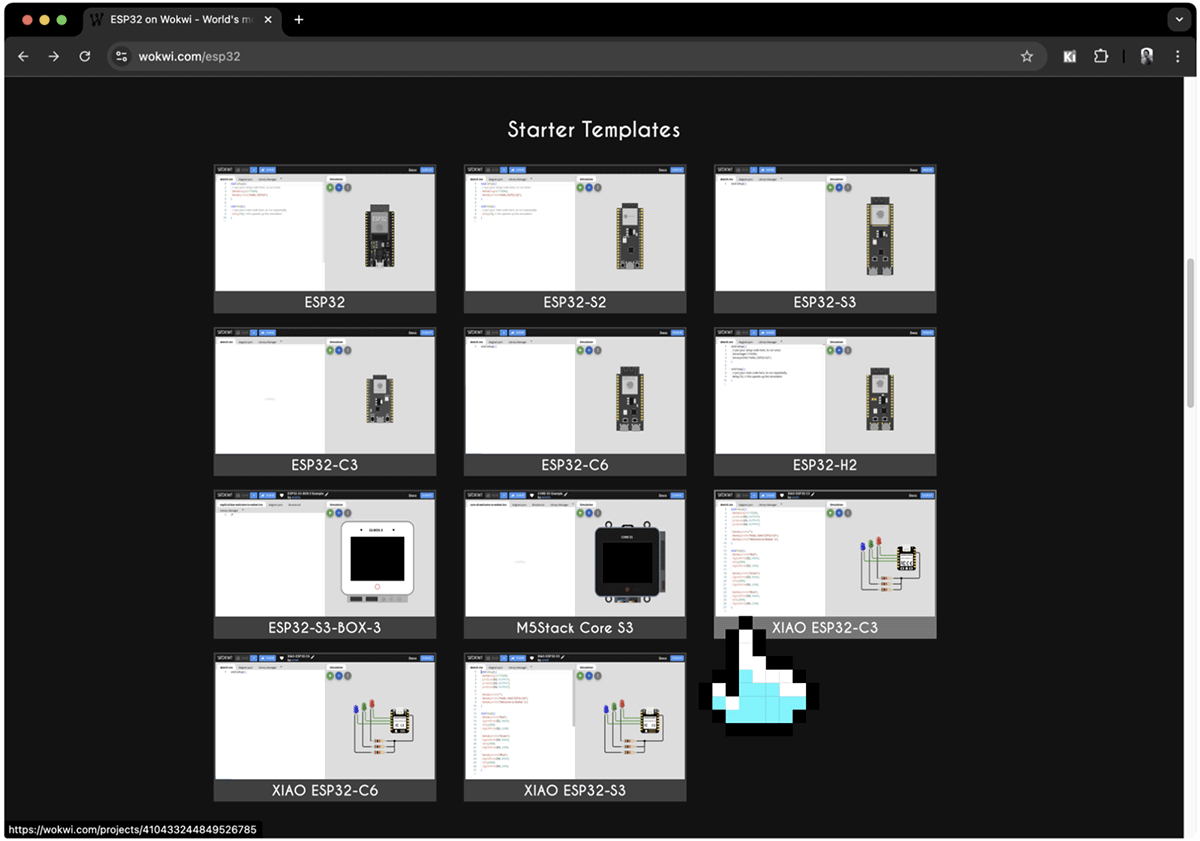
"XIAO ESP32-C3" can be found in the "Starter Templates" section
After entering the XIAO ESP32-C3 sample project, you can directly click the start simulation button under the simulation tab to see the effect of 3 LEDs lighting up in sequence, as shown below.
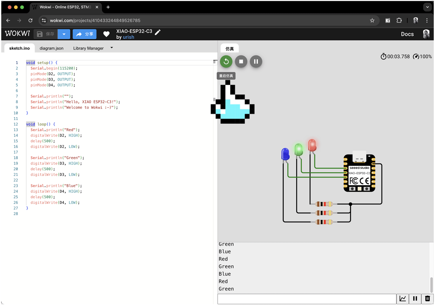
Running the sample program that lights up 3 LEDs in sequence
Since we need to simulate an accelerometer, we can select these unnecessary components and press the delete key to remove them, as shown below.
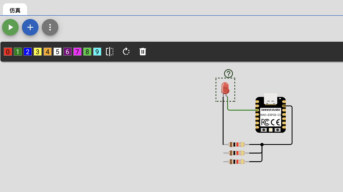
Deleting unnecessary components one by one
Adding the MPU6050 Accelerometer
Since our main purpose is to simulate the IMU sensor functionality, we need to add an MPU6050 accelerometer:
- On the right side of the project interface, click the "+" button in the simulation tab
- Find "MPU6050" in the sensors section
- Add the MPU6050 component to the simulation project, as shown below
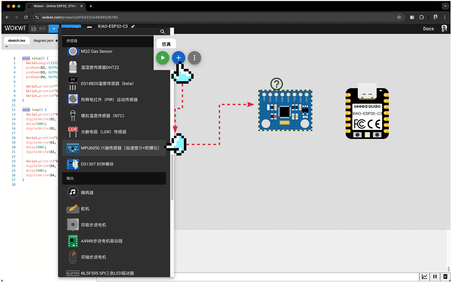
Adding the MPU6050 component to the simulation project
Hardware Connection
Based on the pin definitions of XIAO ESP32C3 and MPU6050, we need to correctly connect these two components:
| MPU6050 Pin | XIAO ESP32C3 Pin | Connection Description |
|---|---|---|
| VCC | 3V3 | Power |
| GND | GND | Ground |
| SCL | D5 (GPIO7) | I2C clock line |
| SDA | D4 (GPIO6) | I2C data line |
| AD0 | GND | Set I2C address to 0x68 |
| INT | Not connected | Interrupt line (not used in this example) |
Use the virtual wiring tool to connect the components, as shown below.
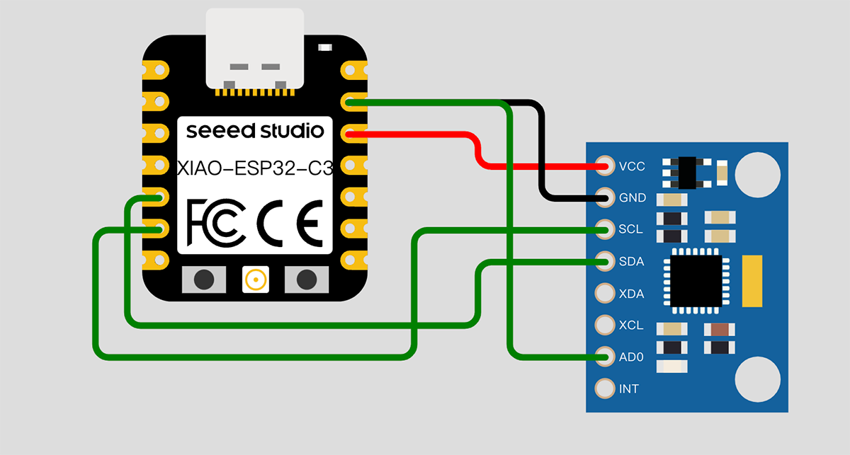
Connection diagram of MPU6050 and XIAO ESP32C3
III. Adjusting Code for the Simulation Environment
Since we are using different hardware platforms and sensors, we need to adjust the code to suit the simulation environment. The main differences are:
- Replacing the LSM6DS3TR-C sensor with MPU6050
- Using libraries and APIs suitable for MPU6050
Simulation Version of the IMU Test Program
I modified the IMU test program as follows:
#include <Wire.h>
#include <MPU6050.h>

MPU6050 mpu;  // Create MPU6050 object

char cmd = ' ';  // Use a single character to store commands

void setup() {
  Wire.begin();
  Serial.begin(115200);
  delay(1000);

  Serial.println("Initializing MPU6050...");
  // Initialize MPU6050, set gyroscope and accelerometer range
  while(!mpu.begin(MPU6050_SCALE_2000DPS, MPU6050_RANGE_2G)) {
    Serial.println("Could not find a valid MPU6050 sensor, check wiring!");
    delay(500);
  }

  Serial.println("Device ready!");
  Serial.println("\nAvailable commands:");
  Serial.println("a - display accelerometer readings");
  Serial.println("g - display gyroscope readings");
  Serial.println("s - stop readings");
}

void loop() {
  if (Serial.available()) {
    cmd = Serial.read();
  }

  if (cmd == 'a') {
    // Read accelerometer data
    Vector normAccel = mpu.readNormalizeAccel();

    Serial.print(normAccel.XAxis);
    Serial.print("\t");  // Use tab for separation
    Serial.print(normAccel.YAxis);
    Serial.print("\t");
    Serial.println(normAccel.ZAxis);
  }
  else if (cmd == 'g') {
    // Read gyroscope data
    Vector normGyro = mpu.readNormalizeGyro();

    Serial.print(normGyro.XAxis);
    Serial.print("\t");
    Serial.print(normGyro.YAxis);
    Serial.print("\t");
    Serial.println(normGyro.ZAxis);
  }
  else if (cmd == 's') {
    cmd = ' ';  // Stop output
  }

  delay(100);  // 100ms sampling interval
}IV. Running the Simulation
Copy the program to the code area on the left, then click the "Start Simulation" button at the top to begin simulation. The result shows build failure, as shown below.
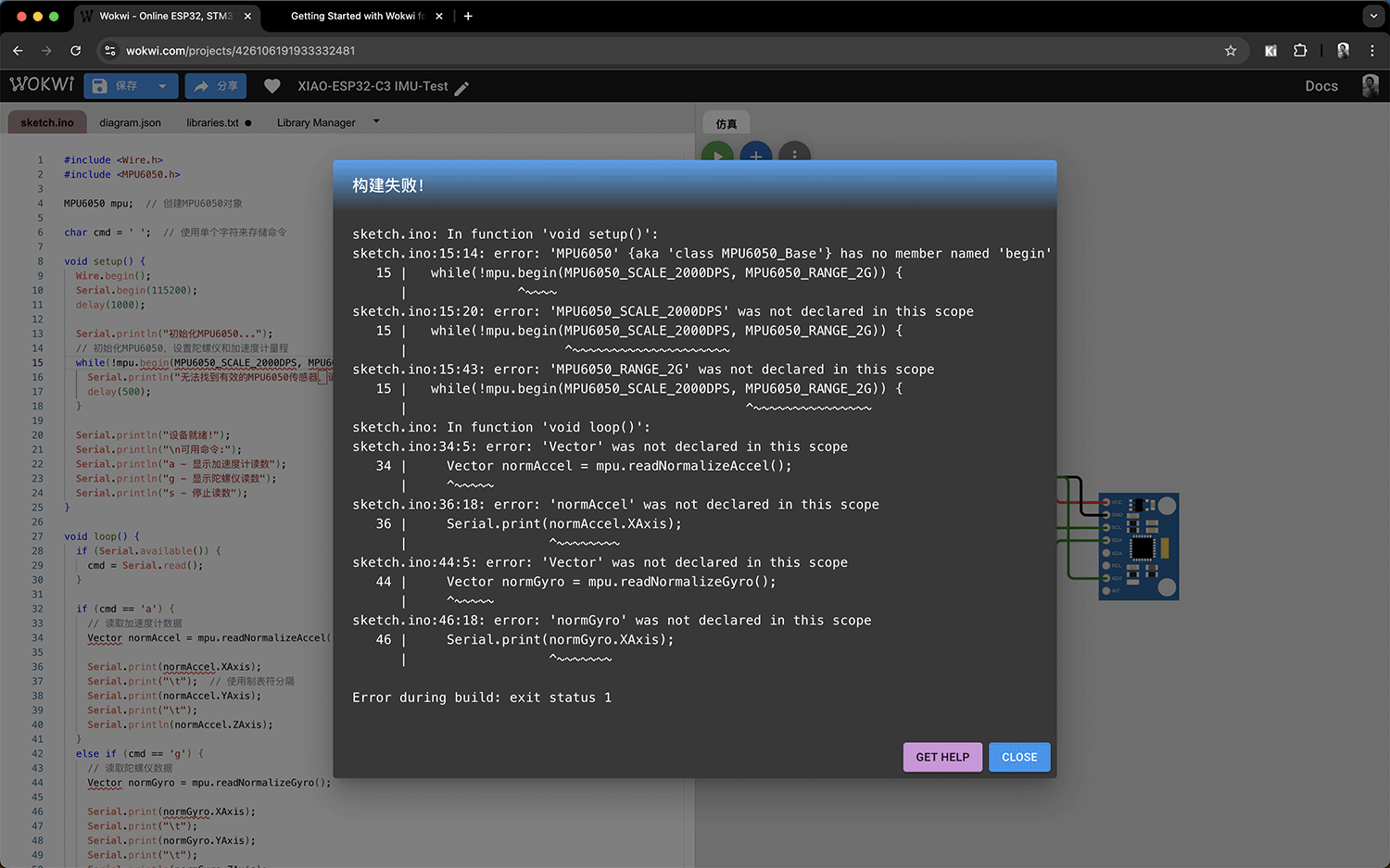
Error prompt on first simulation attempt
Using Claude 3.7 to Solve the Problem
I tried providing feedback about the current situation and errors to Claude 3.7, including the current program, diagram.json, error text, and MPU6050 documentation link. Claude provided the modified program.
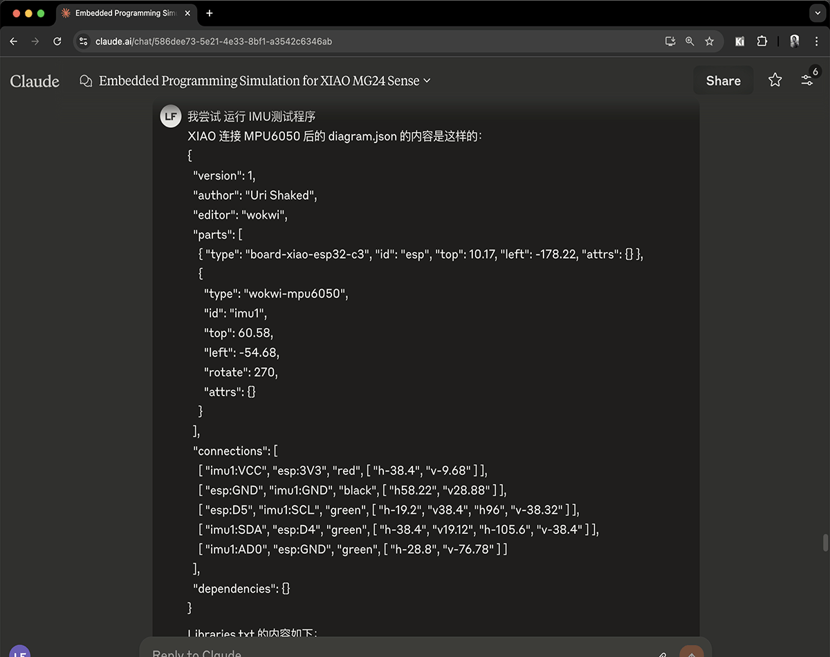
Submitting background information to Claude 3.7
The modified program provided by Claude is as follows:
#include <Wire.h>
#include <MPU6050.h>

MPU6050 mpu;
char cmd = ' ';

void setup() {
  Wire.begin();
  Serial.begin(115200);
  delay(1000);

  Serial.println("Initializing MPU6050...");

  // Initialize MPU6050
  mpu.initialize();

  if (mpu.testConnection()) {
    Serial.println("MPU6050 connection successful!");
  } else {
    Serial.println("MPU6050 connection failed, check wiring!");
    while (1);
  }

  Serial.println("\nAvailable commands:");
  Serial.println("a - display accelerometer readings");
  Serial.println("g - display gyroscope readings");
  Serial.println("s - stop readings");
}

void loop() {
  if (Serial.available()) {
    cmd = Serial.read();
  }

  if (cmd == 'a') {
    // Read accelerometer data
    int16_t ax, ay, az;
    mpu.getAcceleration(&ax, &ay, &az);

    // Convert to g values (1g = 16384 LSB)
    float x = ax / 16384.0;
    float y = ay / 16384.0;
    float z = az / 16384.0;

    Serial.print(x);
    Serial.print("\t");
    Serial.print(y);
    Serial.print("\t");
    Serial.println(z);
  }
  else if (cmd == 'g') {
    // Read gyroscope data
    int16_t gx, gy, gz;
    mpu.getRotation(&gx, &gy, &gz);

    // Convert to degrees/second (1 degree/second = 131 LSB)
    float x = gx / 131.0;
    float y = gy / 131.0;
    float z = gz / 131.0;

    Serial.print(x);
    Serial.print("\t");
    Serial.print(y);
    Serial.print("\t");
    Serial.println(z);
  }
  else if (cmd == 's') {
    cmd = ' ';  // Stop output
  }

  delay(100);  // 100ms sampling interval
}Replace the program on the left with the modified version and try running the simulation again. This time the program runs normally, providing command prompts on the simulated serial monitor. You can input 'a' to view accelerometer data, 'g' to view gyroscope data, or 's' to stop readings.
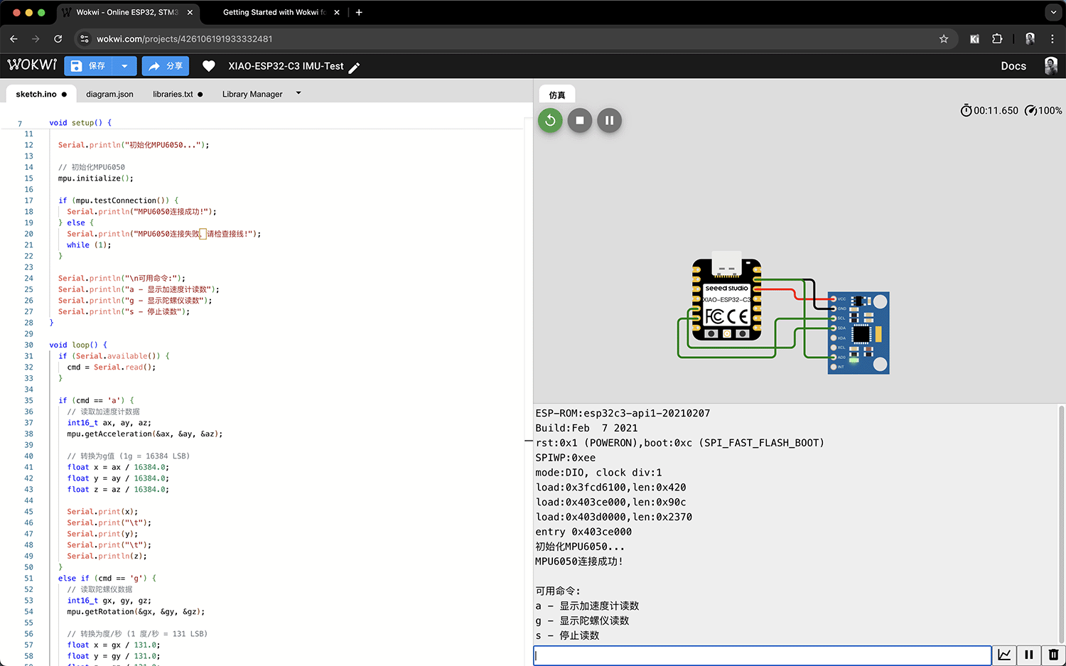
Successfully running the AI-modified program
Simulating Sensor Input
Wokwi provides a visual way to simulate MPU6050 movement:
- Click on the MPU6050 component in the simulator
- Use the control panel that appears to adjust acceleration and angles
- Observe the changes in values on the serial monitor
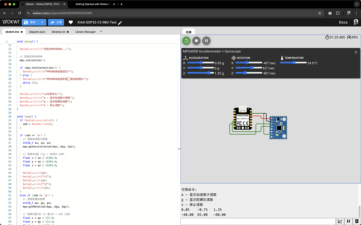
MPU6050 sensor control panel
V. Simulation Results Analysis
Comparison Between Actual Hardware and Simulation Environment
| Aspect | Actual Hardware (XIAO MG24 Sense) | Simulation Environment (XIAO ESP32C3 + MPU6050) |
|---|---|---|
| Processor | EFR32MG24 (ARM Cortex-M33) | ESP32-C3 (RISC-V) |
| IMU Sensor | LSM6DS3TR-C | MPU6050 |
| Sensor Interface | I2C | I2C |
| API Differences | LSM6DS3::readFloatAccelX() | MPU6050::readNormalizeAccel() |
| LED Control | Direct onboard LED support | Requires external LED or GPIO simulation |
Functional Equivalence Analysis
Despite hardware platform differences, the simulation environment can achieve the following core functions:
- Basic I2C communication
- Reading accelerometer and gyroscope data
- Real-time data display and analysis
These functions are sufficient to verify whether our program logic is correct. On actual hardware, only minor adjustments to API calls may be needed.
VI. Advantages and Limitations of Simulation
Advantages
- Test code logic without actual hardware
- Provide visual sensor data input
- Easy debugging and optimization
- Quick verification of algorithm correctness
Limitations
- Hardware platform differences cause some functions to be incompletely simulated
- Cannot test specific hardware performance characteristics
- Some interrupt and timing-sensitive operations may differ from actual hardware
- Cannot accurately simulate low-power characteristics