3D scanning and printing
Topic(s) of this week
- 3D scanning and printing (video, review)
- Identify the advantages and limitations of 3D printing
- Apply design methods and production processes to show your understanding of 3D printing.
- Demonstrate how scanning technology can be used to digitize object(s)
Hero shots
Assignments
Group assignment
- Test the design rules for your 3D printer(s)
- Document your work on the group work page and reflect on your individual page what you learned about characteristics of your printer(s)
Individual assignment
- Design and 3D print an object (small, few cm3, limited by printer time) that could not be easily made subtractively
- 3D scan an object (and optionally print it)
What I think I already know
In the last 2.5 years that I work at the fablab I made quite a few 3D prints. I’ve been using FDM (on ultimaker, Prusa, Ender and Bambulabs) and SLA (on Formlabs). I made my own designs and obviously printed a lot of designs that I got from printables.com and thingiverse.com.
So far I’ve used PLA and a bit of polycarbonate on the FDMs. On Formlabs I’ve used Rigid and Grey Pro.
What I want to learn
In Neils lecture he quickly showed fullcontrolgcode.com which I find very interesting. I think I want to try this. Maybe slice a 3D model and cut and paste its GCode into a FCG generated code? Think CRISPR-CAS for GCode :-) Or create a percussion shaker by creating a closed box with dropplets of filament in it?
SSTM planning
Supply
| Day | Supply | Tasks |
|---|---|---|
| Thursday | 08:00-09:30 (train) | |
| 10:00-18:00 | ||
| 20:00-22:00 (train) | document | |
| Friday | - | |
| Saturday | - | |
| Sunday | 14:00-16:00 | design |
| Monday | 10:00-17:30 (fablab) | first 3D print with FCG |
| cast pressure sensor with piezo | ||
| print group assignment | ||
| 20:00-23:00 | 3D scan and design FCG | |
| Tuesday | 11:00-17:30 (fablab) | second 3D print with FCG |
| Cameo: create flex PCB | ||
| 20:00-22:00 | document | |
| Wednesday | 9:00-12:00 (fablab) | document |
| 12:00-13:00 | Local review | |
| 13:00-14:00 | Regional review | |
| 15:00-18:00 | Neil time |
Tasks
Have you answered these questions?
- Explained what you learned from testing the 3D printers
- Documented how you designed and 3D printed your object and explained why it could not be easily made subtractively
- Documented how you scanned an object
- Included your original design files for 3D printing
- Included your hero shots
- Leave feedback in Nueval that this weekly is ready for evaluation.
WAAG session
GCode
Bas Pijls gave us a workshop on 3D printing. He generated his own GCode. Interesting because that’s similar to what I want to try this week.
You can serially communicate to a 3D printer. Even using Arduino IDE serial monitor. For example Ultimaker 2+ uses ATMega and baud rate 250000.
You can send GCode through this serial interface. GCode command reference on all3dp. More GCode on the website of Marlin.
Most used commands:
G0 is for travel (fast).
G1 is when extruding.
For example G1 X90 Y50 Z0.5 F3000 E1.
You don’t have to use all parameters all the time. For example G1 Z10 will move 10mm up in Z-direction.
Bas went totally crazy on sending Gcodes and made his own interface: gcode generator. This one is specifically for an Ultimaker because the baud rate is hardcoded.
G28 command is to go to home.
M104 S200 command is to set the extruder temperature to 200 degrees Celcius.
M190 S60 command is to set the bed temperature to 60 degrees. And Wait until this is done.
G90 command will make the coordinate system set to absolute mode.
E parameter is for extruding. By default this is set to absolute which is kind of strange because you’ll have to define the exact position of the extruder for every step. Better is to set it to relative mode first using M83 command. E is in mm feedstock. So how many filament is put into the filament. So this should not be set too high! The E parameter should be set for every G1 command.
F is to set the speed of the printhead while extruding. A standard setting is 1000.
For example:
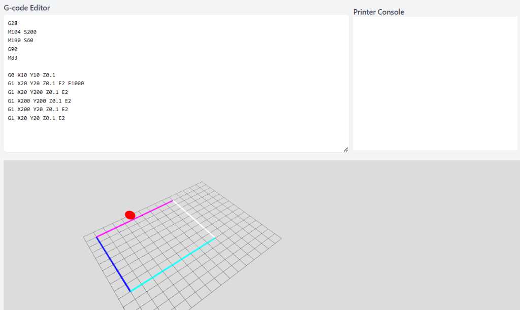
The amount of extruded material depends on the distance of the travel command. If the travel is shorter, the amount of extruded material shoul be shorter as well. So you should calculate the line length and adapt the E parameter accordingly.
So to conclude: GCode is a fairly simple and actually very old language. If you get it, you get it. There’s nothing more to it…
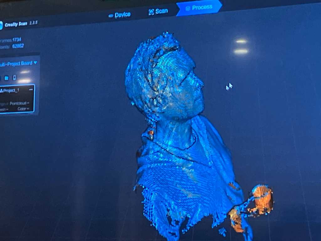
3D scanning
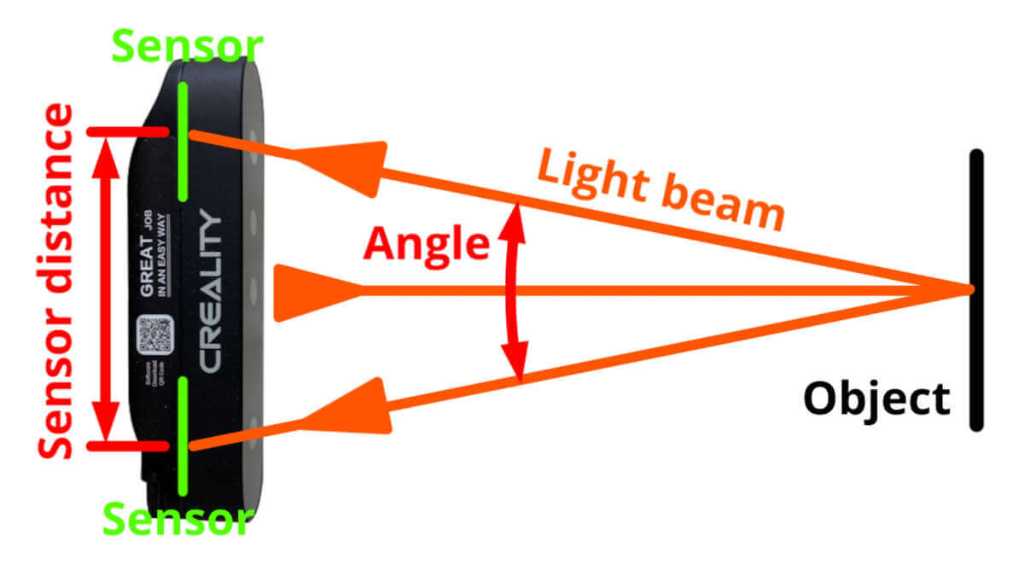
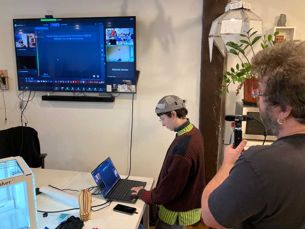
We tried to scan an object using the brand new Creality Ferret at WAAG. Interestingly enough there’s not too much information on the Creality website that explain what kind of technology is used to scan. According to this website it looks like the Ferret is using binocular Near-field infrared.
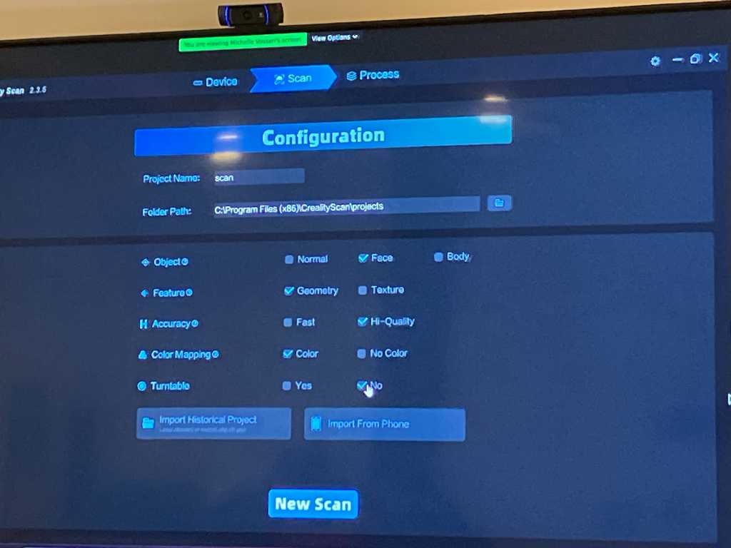
We scanned my head. The settings in the creality software is very important. Although we scanned my head, we had to set the settings to body scan instead of head. No clue why it would find my head in head mode… Later on we found out that you should be really close in order for the software to properly detect.
One click optimization took a very long time, but finally it did something:
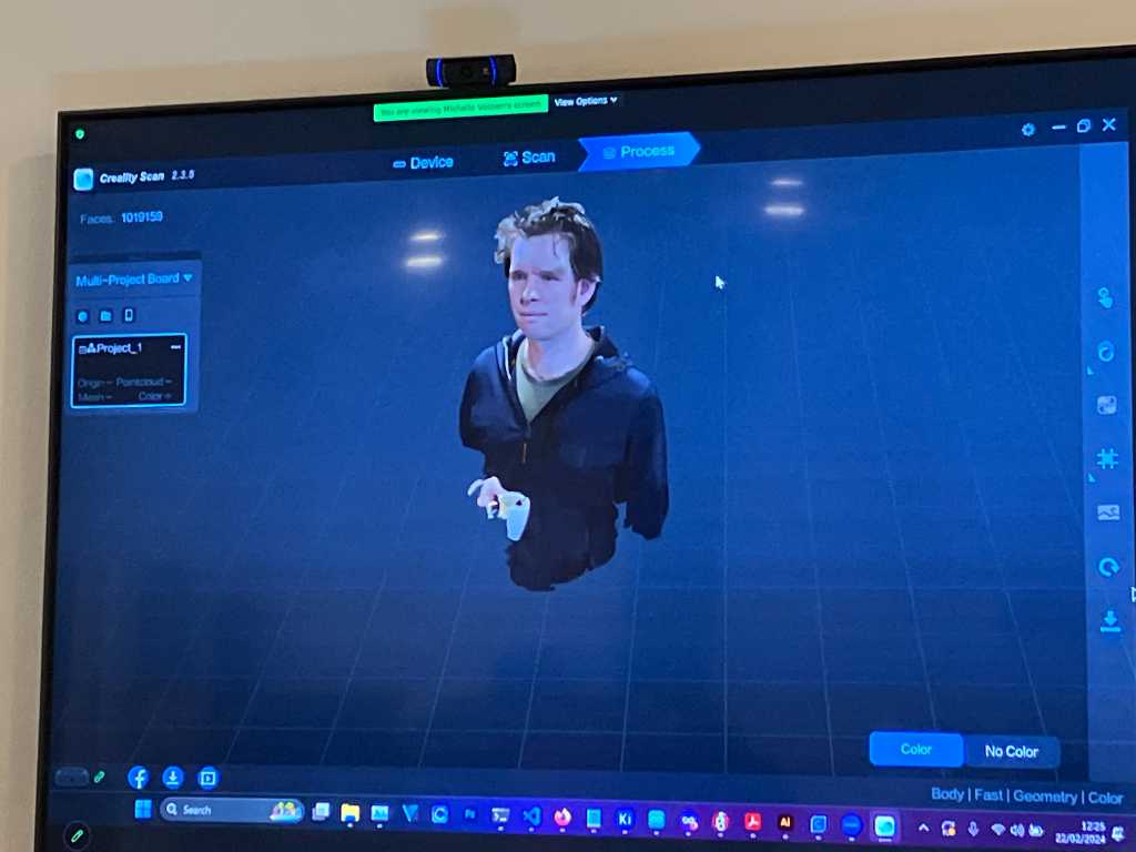
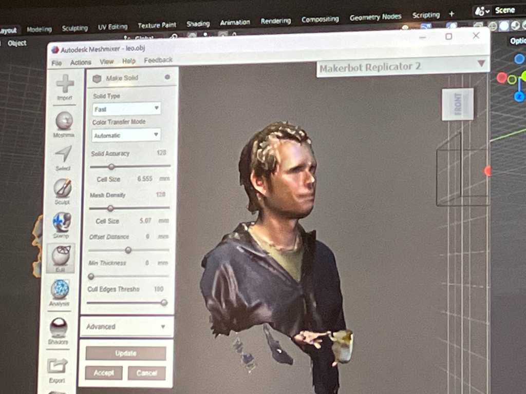
Next we exported it as obj and open it in Autodesk Meshmixer. There a solidify function in edit-make solid.
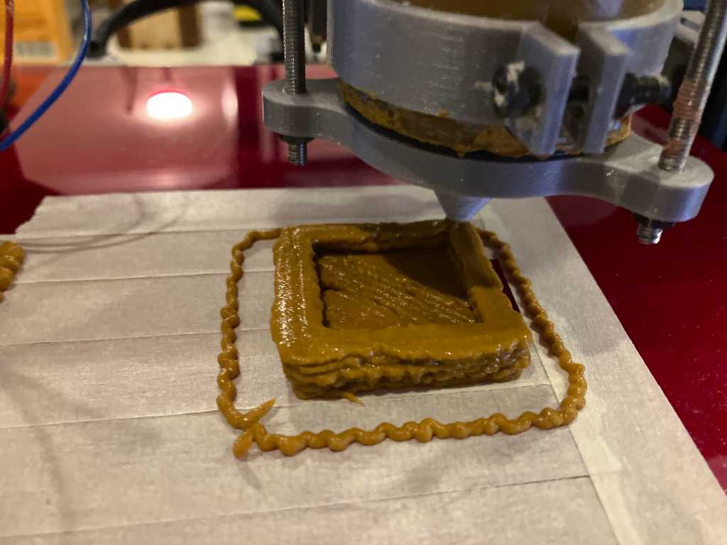
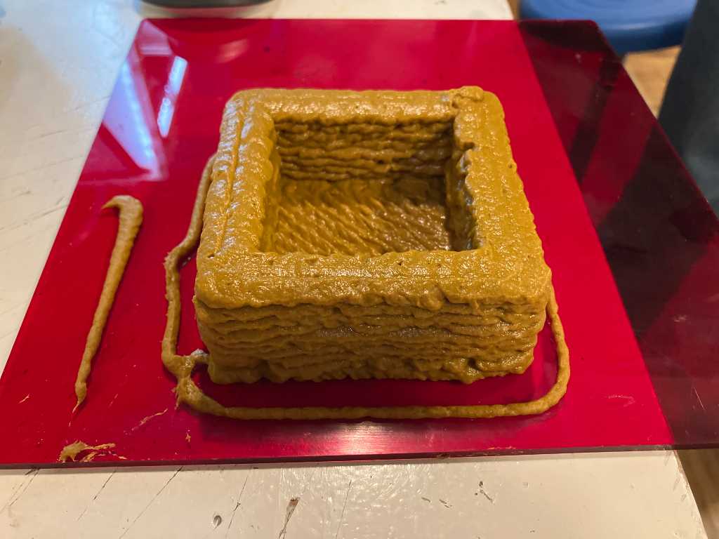
bio material printing
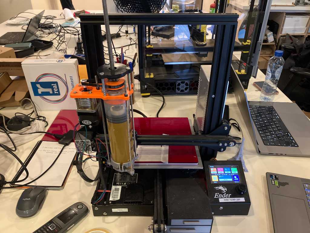
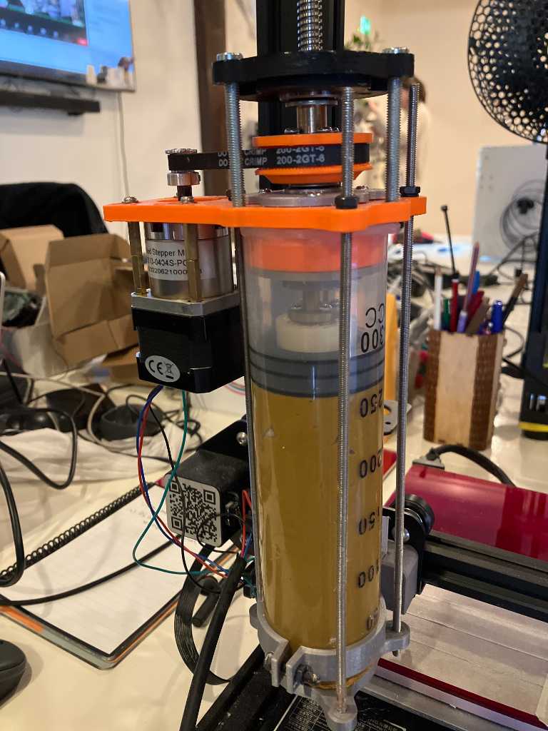
Laura Weller gave us a presentation of printing with bio materials. This is a converted Ender with a big syringe of goo.
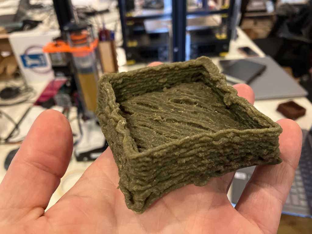
The green open box is the most successful Laura was able to print up to now.
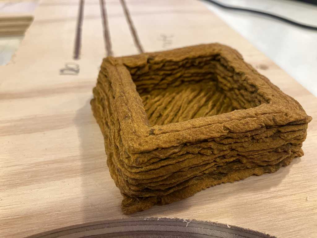
The biomaterial is based on cellulose powder with maizena and egg box pulp (very fine grinded) and maizena for color. It solidifies nicely because of the maizena.
After printing you can leave it to dry for about 10 days or bake / dehydrate to make this time shorter.
Slicing is done using Prusa slicer and control of the printer is done using pronterface printrun. Nozzle size currently is 2mm.
There is no heating, so cold pushed out of the syringe.
The end result after days of drying:
Group assignment
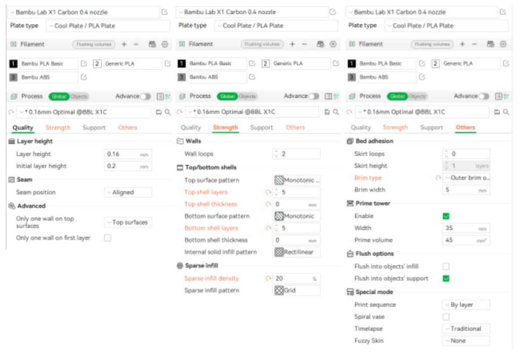
Our goal is to print the Bengine in various materials with as little changes to the default profile as possible. Stock settings first, maybe adapt a little bit if required.
As we work remote, we decided to print bengines on the printers that we have in our labs using different types of material. The documentation of my groupmates is here:
Vera
Edwin
Joe
- Use slicer of manufacturer of the 3D printer
- Stock 0.4mm nozzle
- 0.15mm layer height
- print speed 60mm/s
- no support
- First try without brim (only when needed add a brim).
- Infill pattern grid
- Infill density 20%
- 2 wall lines, 5 top & bottom lines (meaning 0.8mm wall thickness, 0.75mm top-bottom thickness)
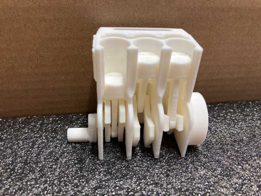
The Bengine checks 20 different features:
- 0.7mm channel through crankshaft
- 1.2mm channel to cooling chamber
- 1mm hole in vertical plane
- 0.3mm Embossed hex
- 1mm hole in horizontal plane
- 0.5mm hole in horizontal plane
- 20mm Bridging
- Freestanding overhang
- Freestanding pipe
- Thinribs
- 0.5mm holes close to build surface
- 0.86mm embossment at 5deg
- Detailed embossment
- Cooling chamber/internal surfaces
- Valvepockets / Vertical resolution
- Radius
- Warpingtest
- Arching overhang (10mm Radius)
- Bed adhesion
- Elephant footing test base hole 0.5mm, chamfering: 0.8mm, 0.5mm, 0.3mm, 0.1mm, 0mm

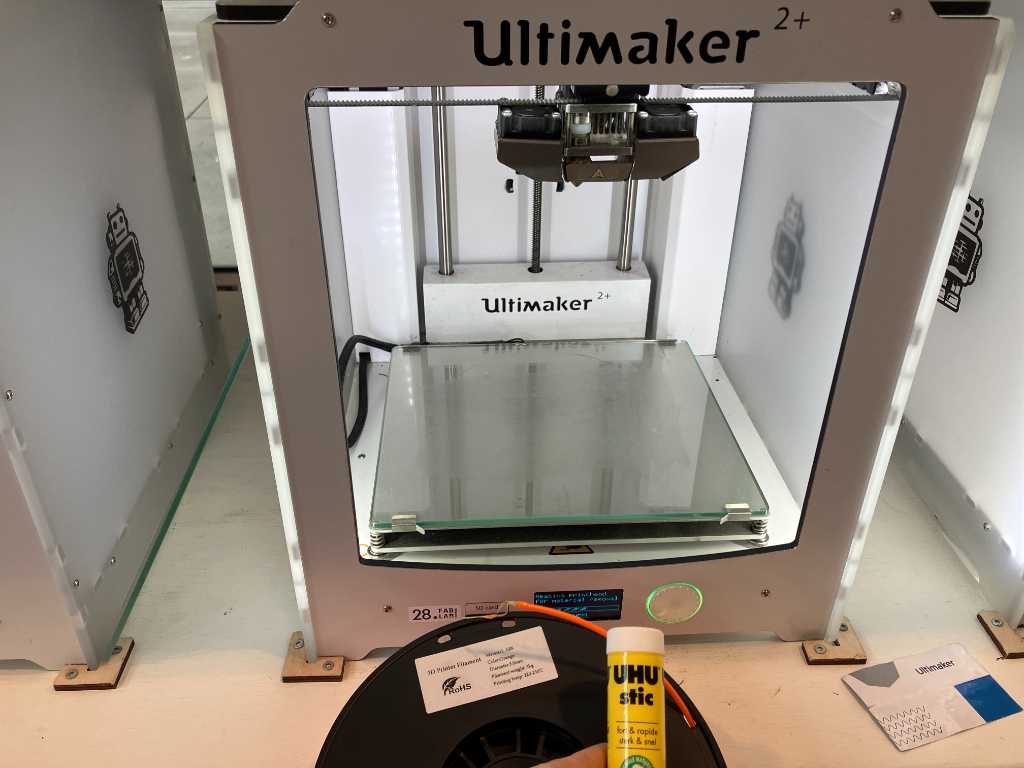
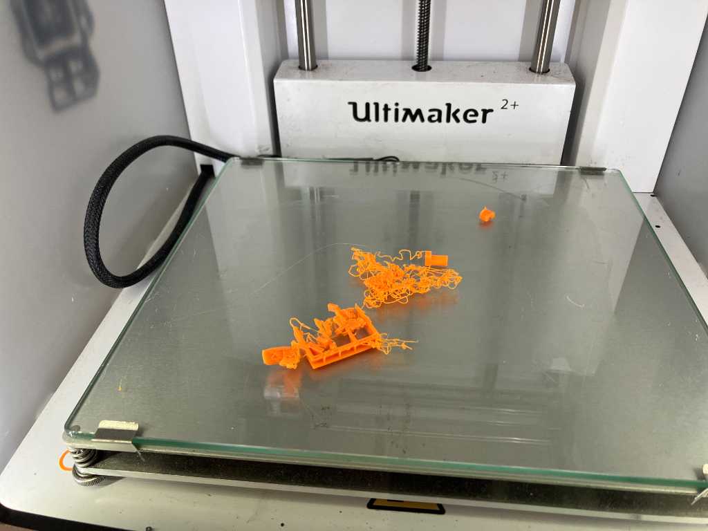
Ultimaker 2+ with standard PLA Grey
First try is on the Ultimaker 2+ using standard PLA. First try fails. Z-level not properly calibrated yet.
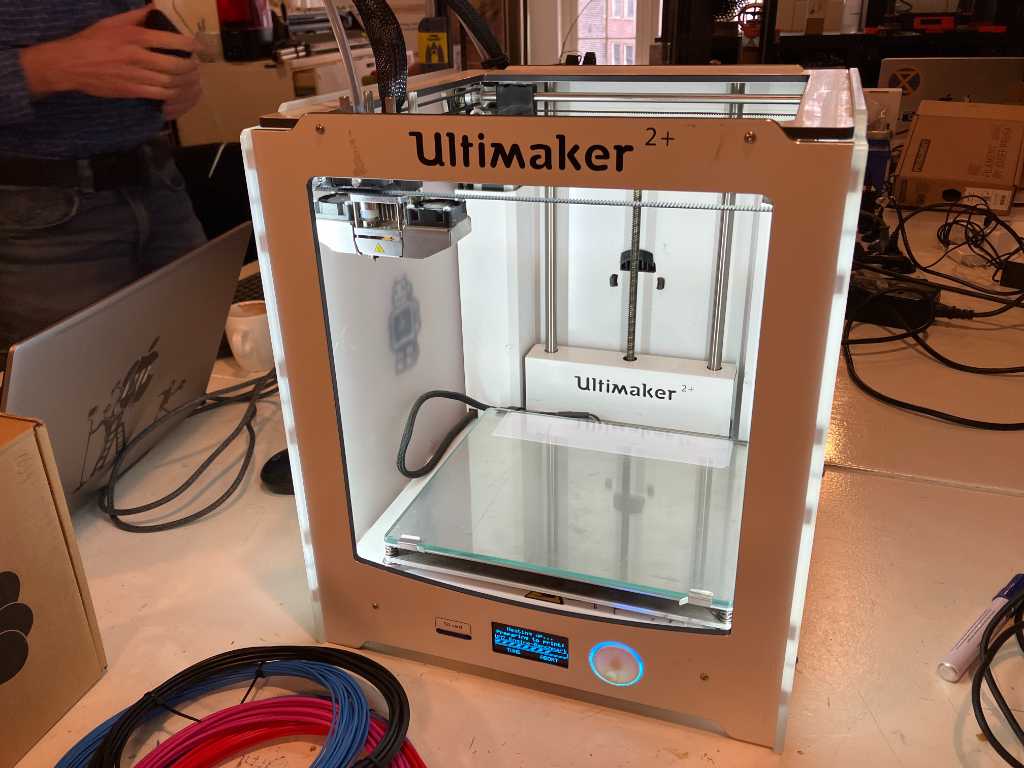
2nd try was much better:
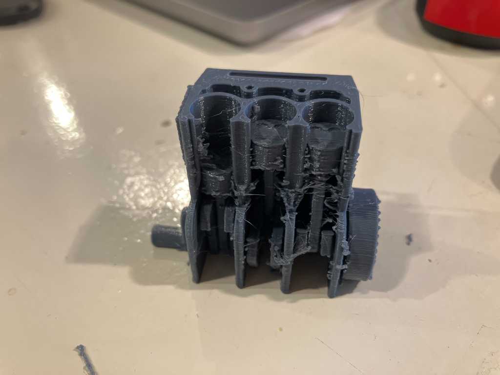
But it has too much stringing, so it can’t move. Stringing is caused by retraction rate, too old (and wet?) filament.
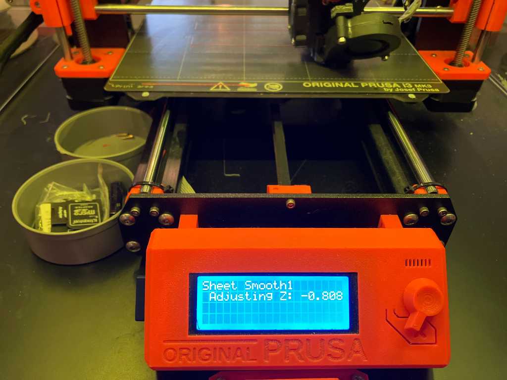
Prusa i3MK3s with Prusament PETG
We’re going to try Prusament PETG on a Prusa i3MK3s.
The first try failed miserably. The Z-level wasn’t calibrated yet after the machine was used to print on textile…
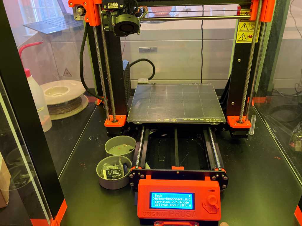
So let’s adjust the Z:
But still not good:
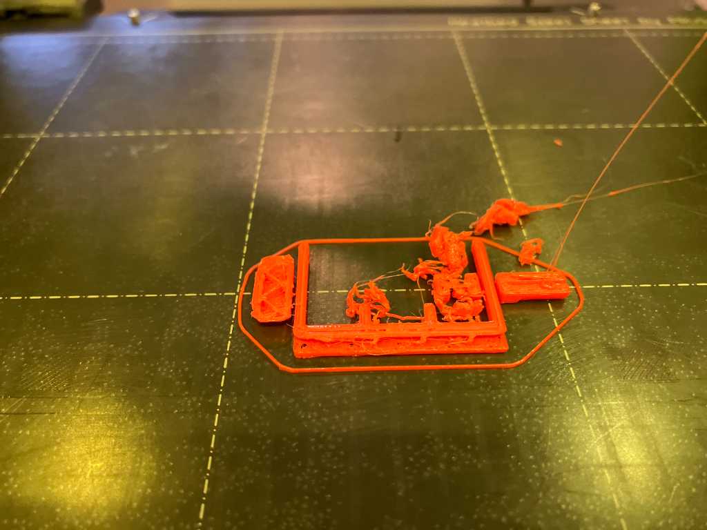
I sliced it using Prusa PETG setting, but is should have been Prusament PETG. #fail. That has a 10 degree higher setting. We also cleaned the nozzle and redid the Z calibration. Still no luck. We cleared the bed using IPA. This is looking good.
The end result is not too good. Lots of stringing:
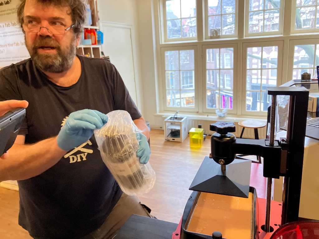
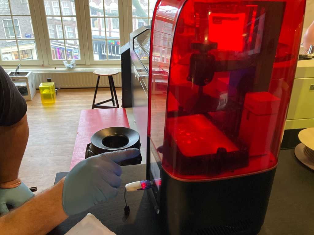
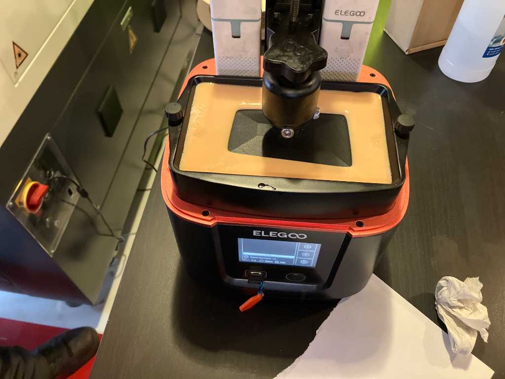
Elegoo Mars 3 with standard photopolymer resin
Henk tried the Bengine on the Elegoo SLA printer. First leveling the Z:
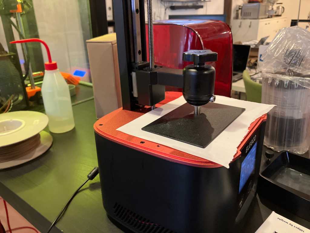
We’re using standard beige photopolymer resin. But don’t fill it too much. Not beyond max! This stuff smells…
Here we go:
Midway check to see if it sticks to the bed and photo when done but uncured:
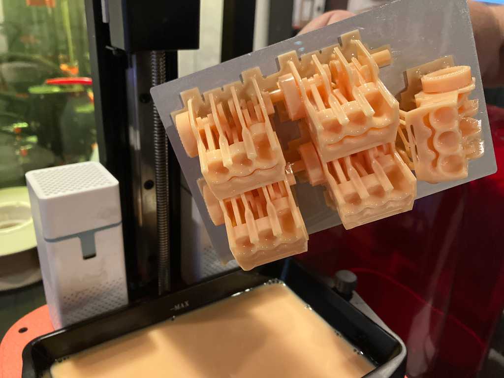
Cleaning in IPA and UV curing:
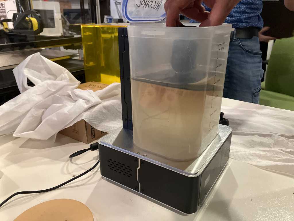
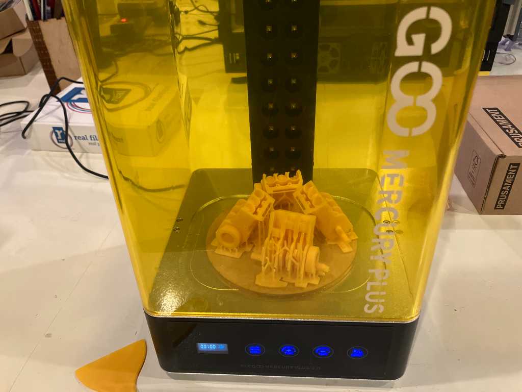
The end result was quite nice. You can’t print on a SLA without brim, so we had a hard time making the bengine work. Stuff broke off. But eventually this bengine worked. Kinda.
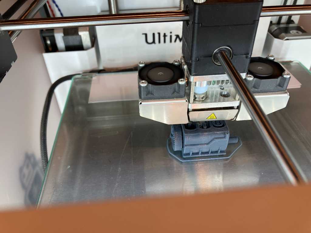
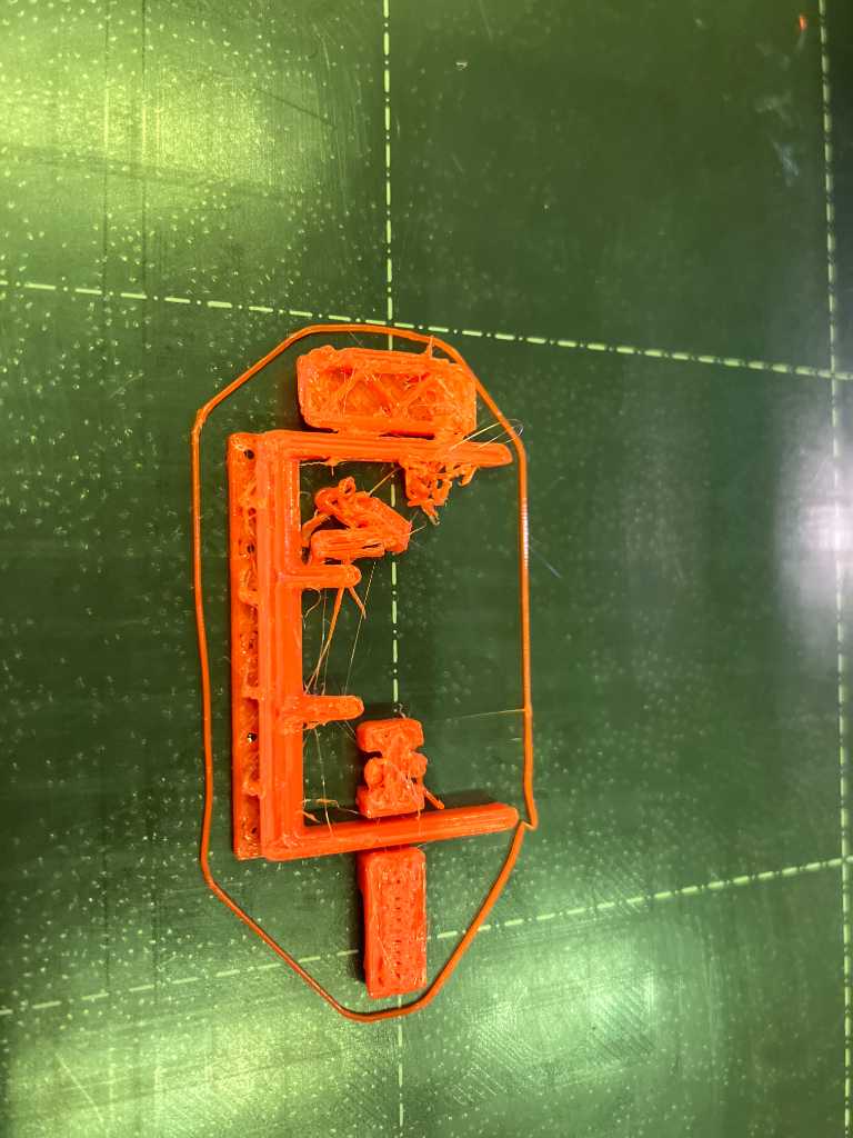
Bambulabs X1C with standard PLA White
Now let’s try on the Bambulabs X1C in our fablab, using standard white PLA.
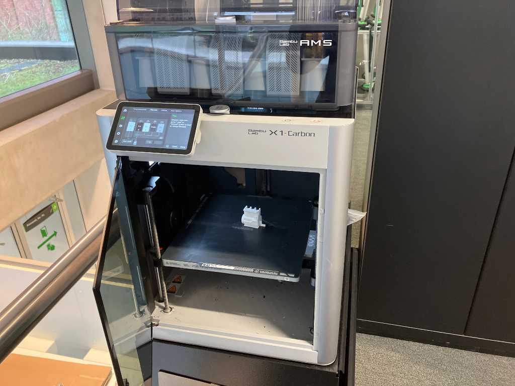
 I used the PLA buildplate with PVA gluestick.
Looking good and working! Unfortunately 1 of the pistons snapped off.
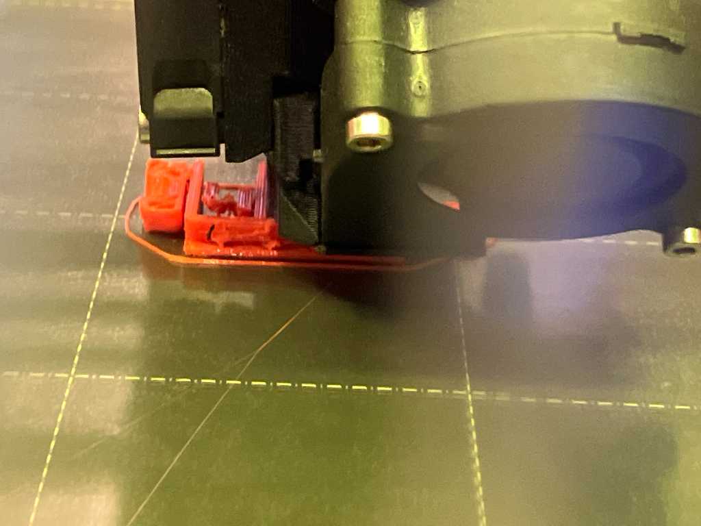
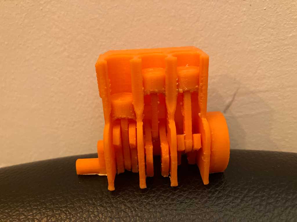
Bambulabs X1C with Devil Design PET-G dark orange
Next material is PETG dark orange on the Bambulabs, using textured PEI buildplate, no glue.
I’ve set it to 255 degrees printing temperature, 70 degrees buildplate (default for PETG on Bambu).
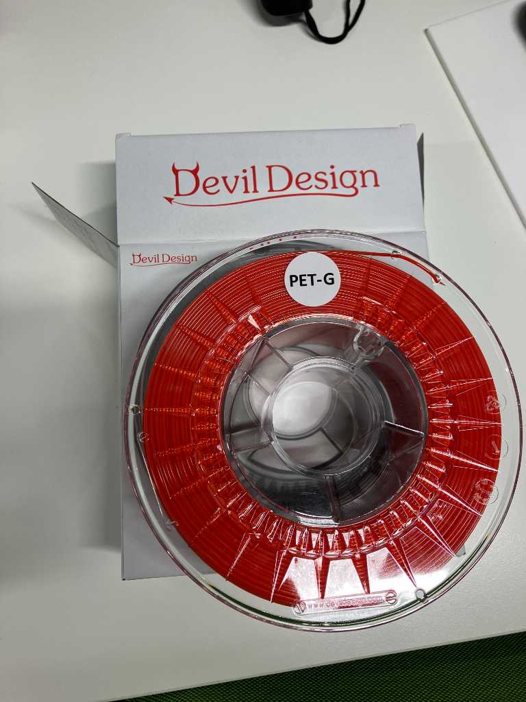
This is a nice one! It looks good, hardly any stringing, printed in about 1 hour and fully working. Great!
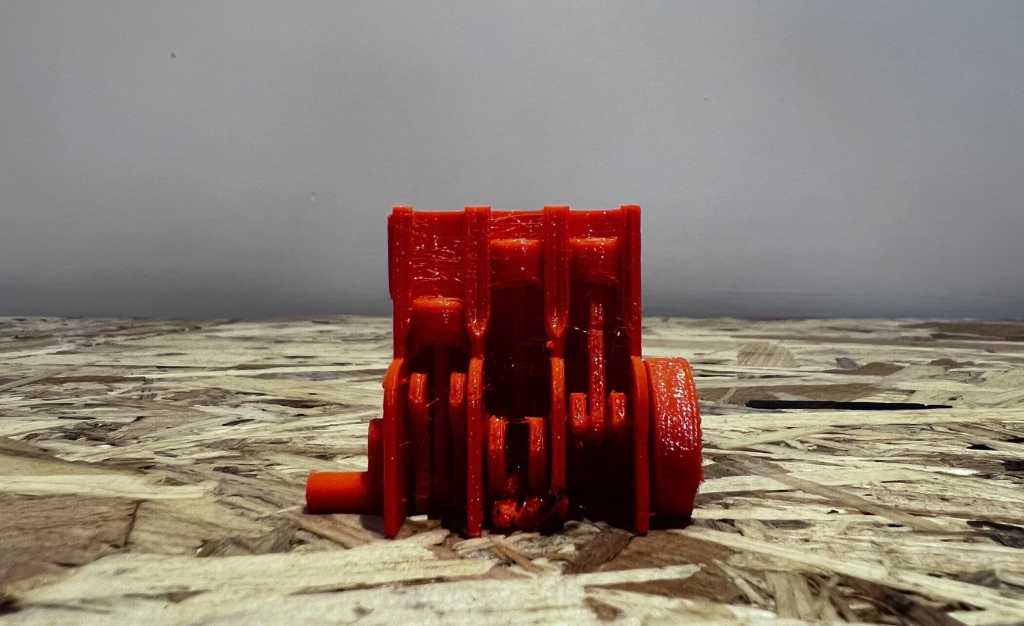
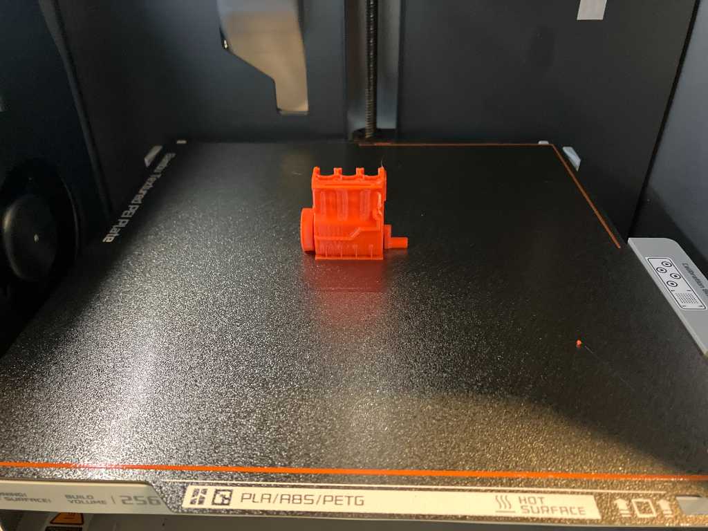
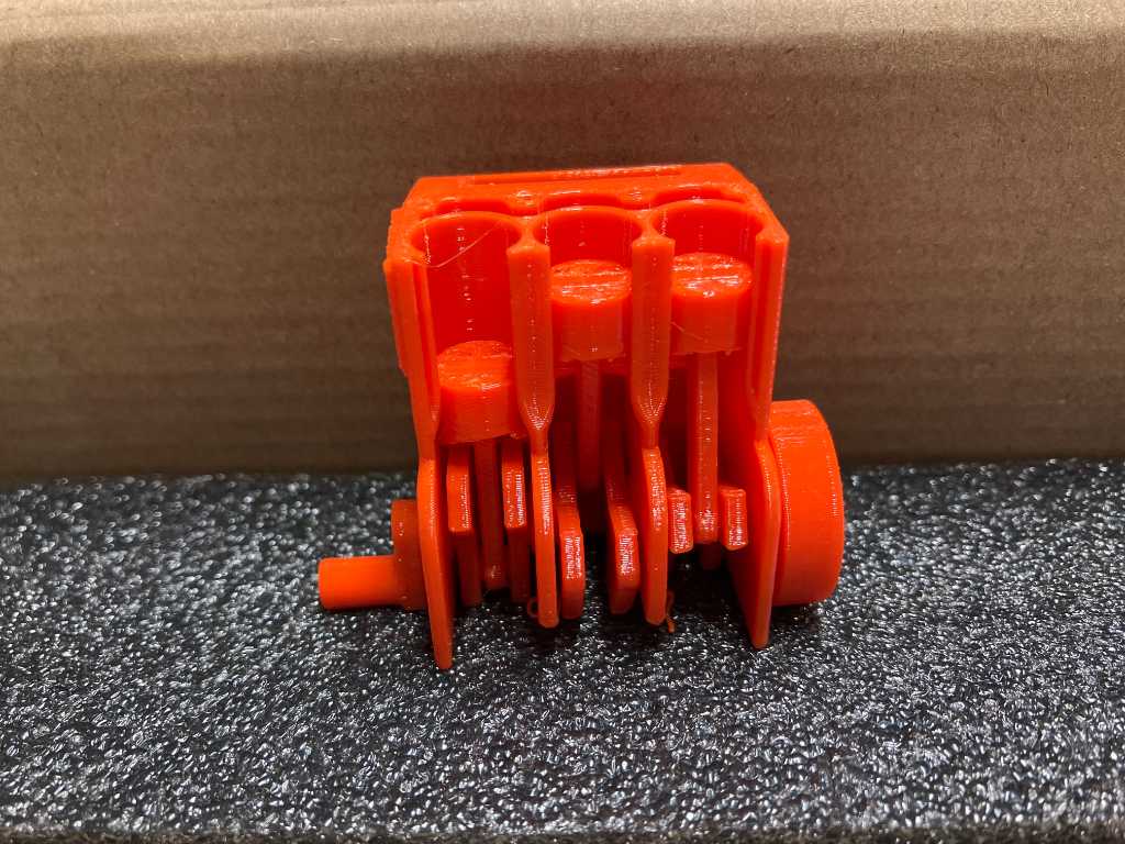
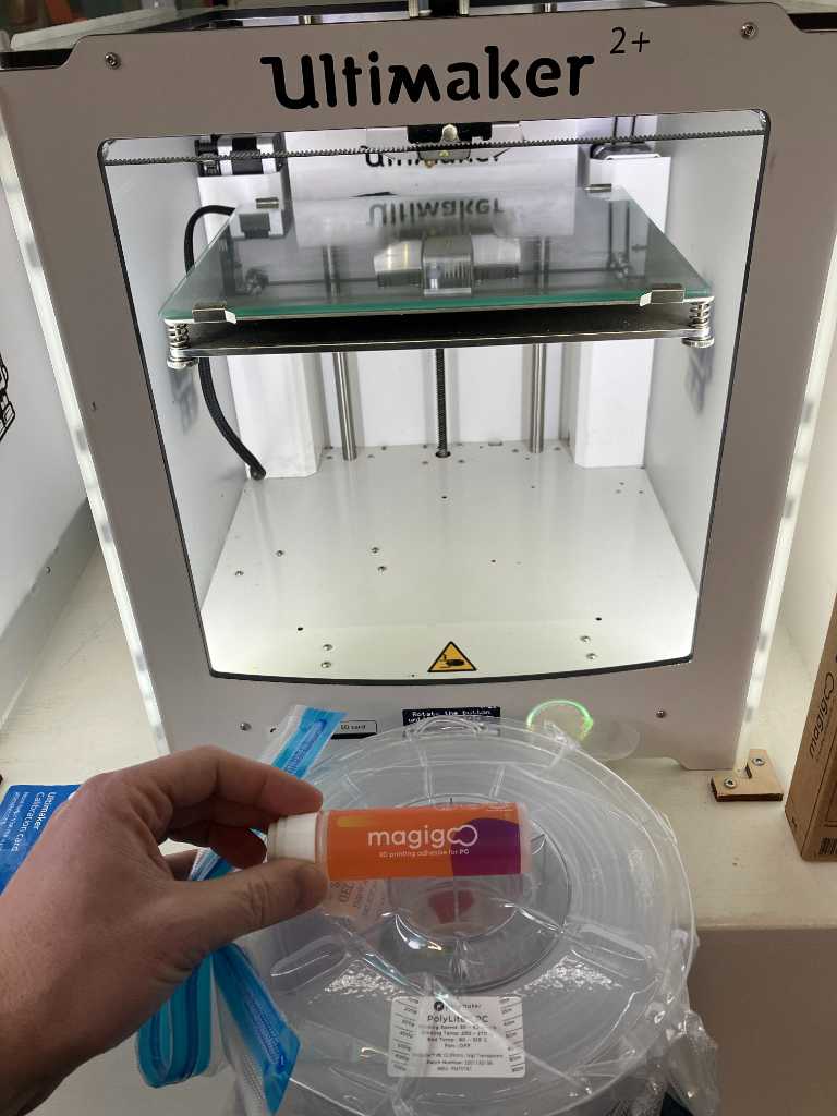
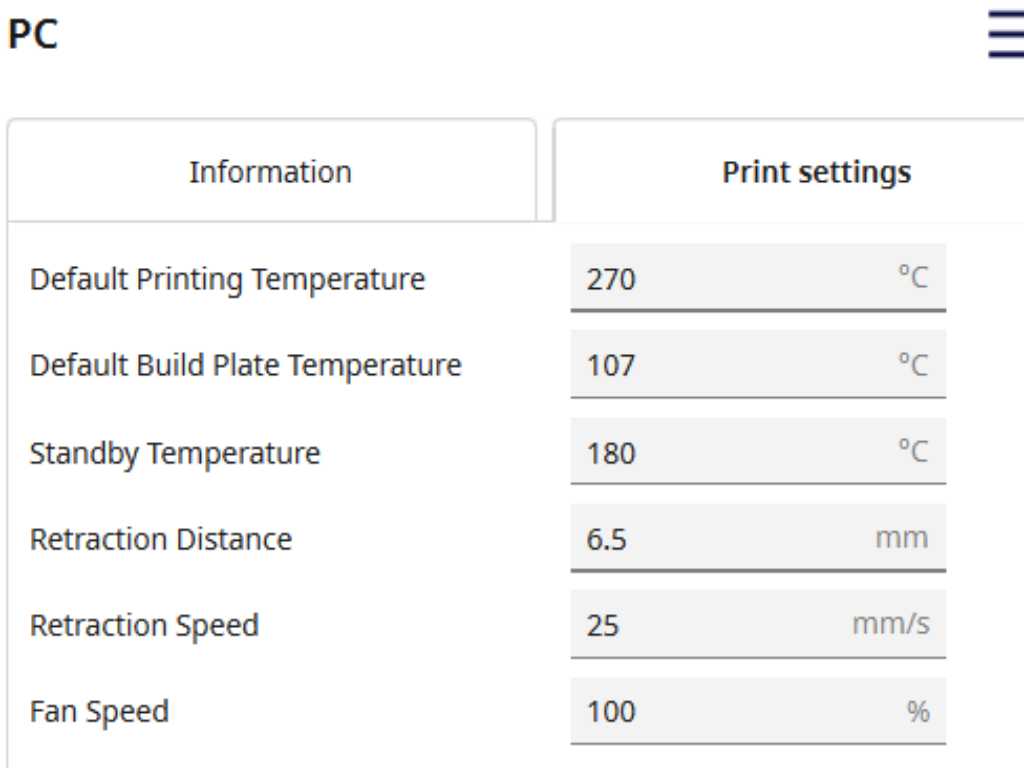
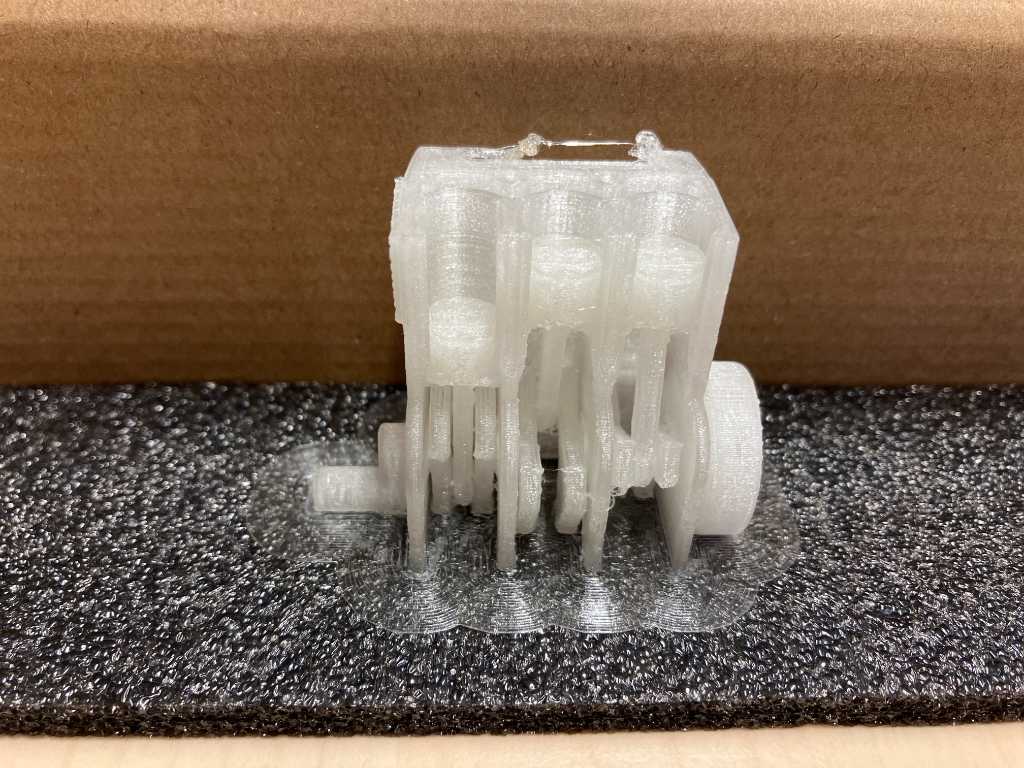
Ultimaker 2+ with Polymax Polycarbonate transparent
We also have polycarbonate in our fablab. This is 2.85mm so should be used on the Ultimaker. As instructed by the manufacturer, the only change to the default setting that I made was to always turn the fan off. I used Magigoo adhesive glue on the glass plate to make sure the PC sticks.
After a few tries I couldn’t get the first layer to properly adhere, so I decided to print with a brim. But oops, after returning 4 hours later it turns out I’ve turned on support instead of brim… #fail
I “quickly” made another one and that one’s looking nice. It’s not moving, and the overhang test on the back failed. So not all that great, but still a nice bengine.
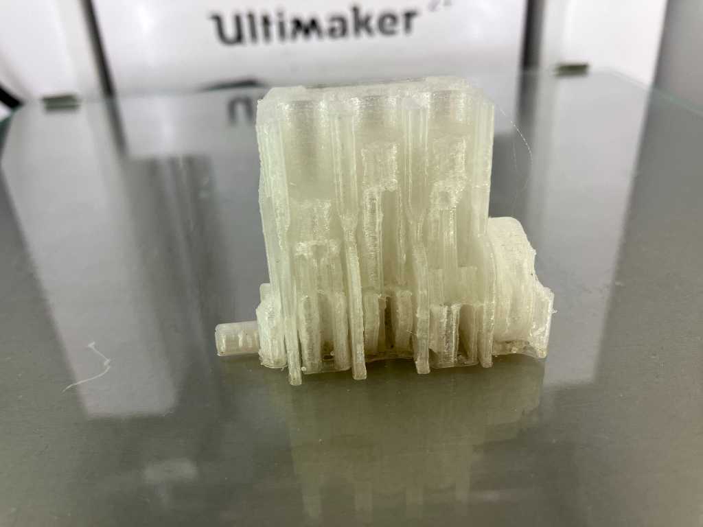
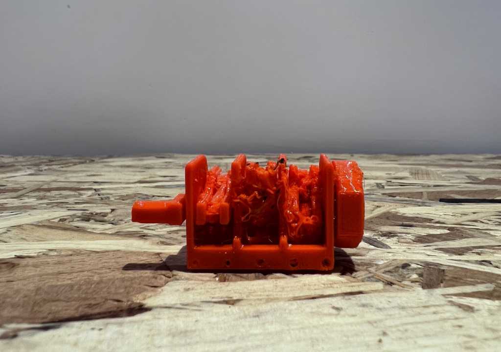
Ultimaker 2+ with ABS orange
One more. I found a spool of 2.85mm no-name ABS orange. Never printed that before. Luckily we have a well ventilated fablab.
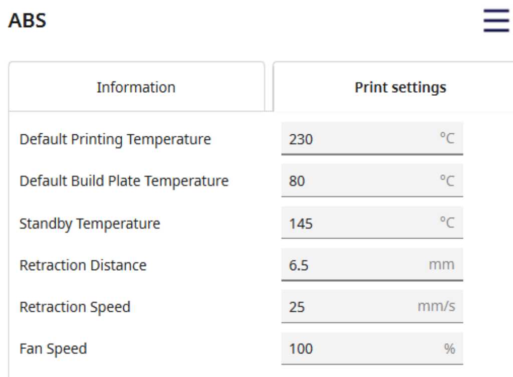 I used default settings, with fan off, and UHU glue stick on the glass printbed.
This failed quite a few times as well due to improper bed adhesion. So I went for the brim:
Again nice print. Bit rough and not working. But it is my first time printing ABS and that went quite well.
Conclusion
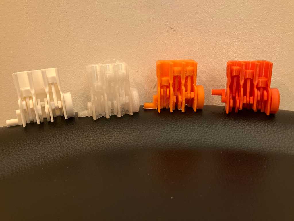
So here are 4 bengines. Together with the bengines that my groupmates made, we were able to create hardly any properly moving bengines. So it’s a real good test design :-)
PETG was easy to print, and working. So I do understand why that material is used often. Default settings just work, both on Prusa as well as on Bambulabs. PLA is a good material to print with as well. Also here default settings work fine. But the material is much weaker than PETG.
Individual assignment
FullControlGCode Shaker
I’m going to try to make a percussion shaker by creating a closed box with granules of filament in it. Something like this:
I watched the fullControlGcode tutorial. The software used to run in Excel using VBA. Nowadays its a python script that can be found in this repository. The python youtube tutorials can be found here. There’s also a website called fullcontrol.xyz.
FCG is about unconstrained GCode generation. It allows you to specify exactly what the 3D printer should do. So no 3D design program or slicer software is used. Pure GCode. The nice thing is that it allows you to do things that you can’t design in 3D software. For example use stringing as a design feature instead of a print failure. It also allows for non planar designs.
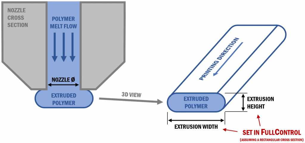
In FCG the amount of material that is extruded is defined by the cross-sectional area of the extrusion, defined by its width and height. For simplicity, this is defined as if the extrusion has a rectangular cross section.
from the manual
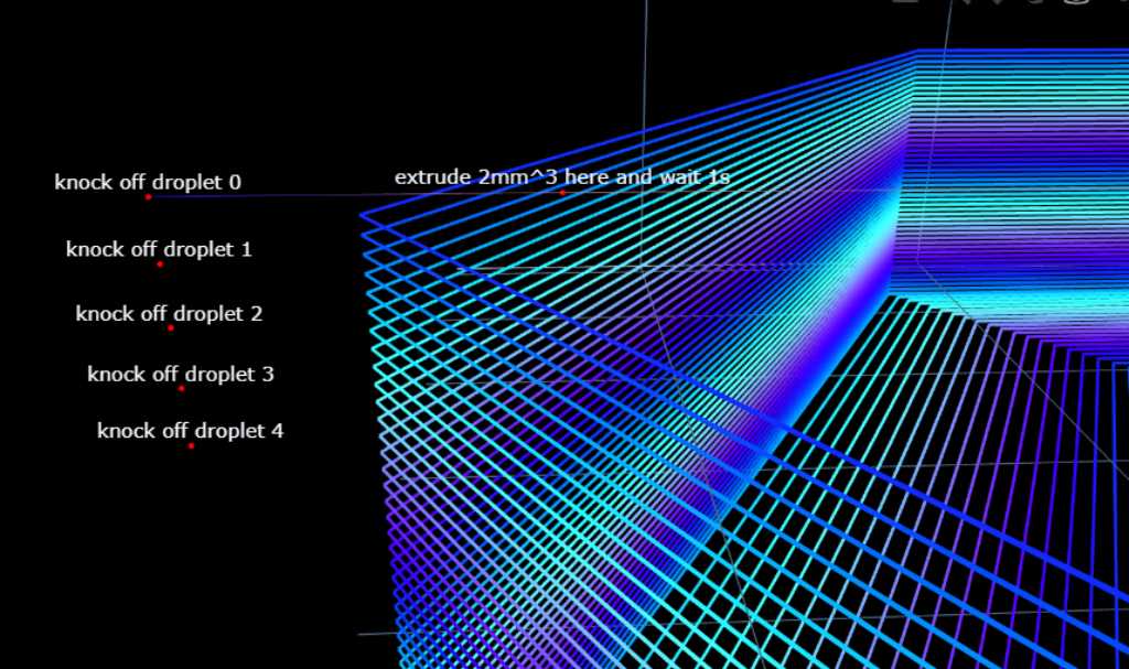
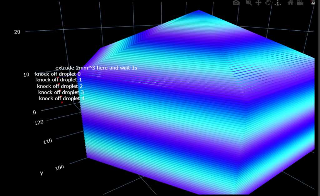
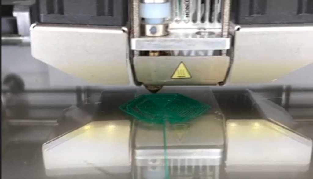
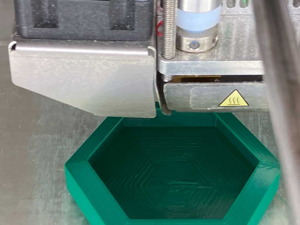
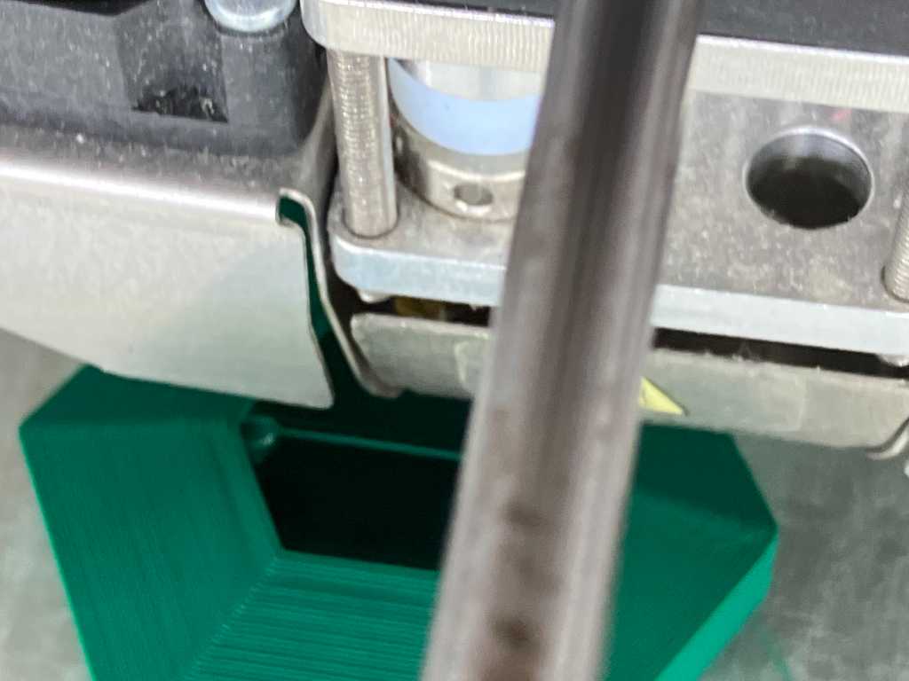
Especially with the help of this youtube tutorial of FCG, I created a colab that might make me a shaker. It creates a bottom layer and a wall, thus creating a bowl. Next the printhead goes to a point within the bowl close to the wall. It starts to stationary extrude some filament, waits a bit (hopefully it’ll cool a bit so it’s less sticky), retracts the filament (hopefully the extruded bit will snap off or at least be prone to snapping) and then crosses the wall at the Z-height just above the wall. This should knock the extruded droplet of filament off. It should drop into the bowl. And that happens a couple of times. So it creates a bowl of droplets of filament that hopefully don’t stick to the bottom. Next it covers the top of the bowl. And there you have it. A shaker. Hopefully.
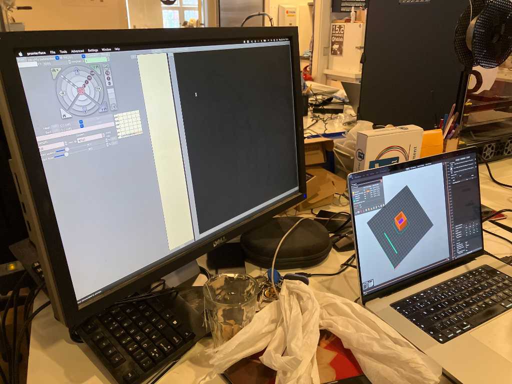
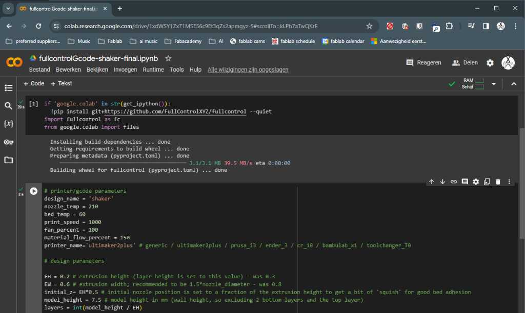
With FullcontrolGCode you use a Google Colab notebook to program. Or you can download the Python script and program on your local computer. I used the Google Colab, starting with the design template that was made by the creator of FCG.
This is how the Google Colab notebook looks like.
The code for the first design I made:
# design parameters
EW = 0.8 # extrusion width
EH = 0.3 # extrusion height (and layer height)
initial_z= EH*0.4 # initial nozzle position is set to a fraction of the extrusion height to get a bit of 'squish' for good bed adhesion
layers = 50
# generate the design (make sure you've run the above cells before running this cell)
initial_x = 100
initial_y = 100
radius = 25
circle_segments = 6
droplet_offset = 3
droplets = 5
droplet_volume = 2
droplet_speed = 50
bottom_circles_radius = fc.linspace(0,radius,round(radius/EW)) # calculate amount of circles required to properly fill the outer circle. going from inside to outside
# initial steps
steps = []
steps.append(fc.Extruder(units='mm3')) # set extrusion units to mm3 to make it easier to manually calculate E values
steps.append(fc.ExtrusionGeometry(area_model='rectangle', width = EW, height = EH))
steps.extend(fc.travel_to(fc.Point(x=initial_x, y=initial_y, z=initial_z))) # go to start position
# bottom layer
for circle_position in range(round(radius/EW)):
steps.extend(fc.circleXY(fc.Point(x=initial_x, y=initial_y, z=initial_z), bottom_circles_radius[circle_position], 0, circle_segments)) # add a circle with circle_segments
# wall
initial_wall_z = initial_z + 1 * EH
for layer in range(layers):
steps.extend(fc.circleXY(fc.Point(x=initial_x, y=initial_y, z=initial_wall_z + layer * EH), radius, 0, circle_segments)) # add a circle with circle_segments
# granules
droplet_location_z = initial_wall_z + layers * EH
droplet_location = fc.Point(x=initial_x - radius + droplet_offset, y=initial_y, z=droplet_location_z)
droplet_knockoff_location = fc.Point(x=initial_x - radius - droplet_offset, y=initial_y, z=droplet_location_z )
steps.extend(fc.travel_to(droplet_location)) # travel to edge of circle minus offset (stay inside circle) without extruding
for droplet in range(droplets):
steps.append(fc.StationaryExtrusion(volume=droplet_volume, speed=droplet_speed)) # stationary extrude droplet_volume mm^3 with speed of droplet_speed.
steps.append(fc.ManualGcode(text='G4 P1000')) # add GCode to wait 1000ms. Not sure if needed because retract is also used
# not sure what to use to retract properly: negative extrusion? Or printerCommand id retract? And should the last one be followed by unretract as well?
# steps.append(fc.StationaryExtrusion(volume=-1, speed=50)) # stationary negatively extrude 1mm^3 with speed of 50 (is tris retraction?).
steps.append(fc.Extruder(on=False))
steps.append(fc.PrinterCommand(id='retract'))
steps.extend(fc.travel_to(droplet_knockoff_location)) # travel across the wall of the circle to knock off the filament droplet
steps.extend(fc.travel_to(droplet_location)) # go back
steps.append(fc.Extruder(on=True))
steps.append(fc.PrinterCommand(id='unretract'))
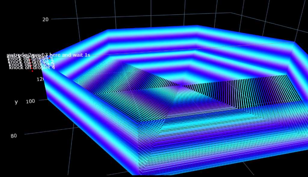
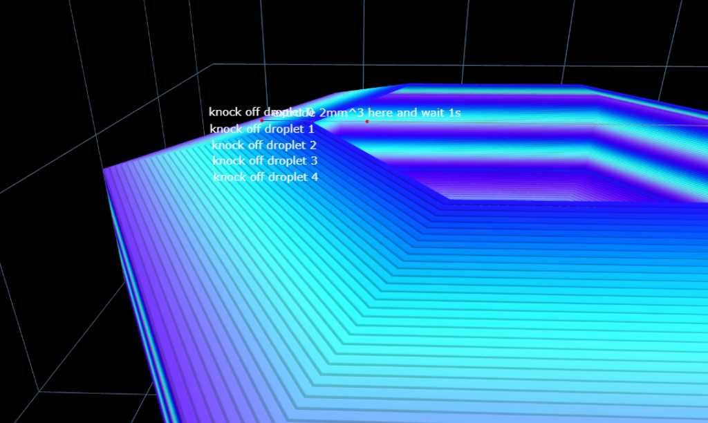
# some labels for explanation
steps.append(fc.PlotAnnotation(label='extrude 2mm^3 here and wait 1s',point=droplet_location))
for droplet in range(droplets):
steps.append(fc.PlotAnnotation(label='knock off droplet ' + str(droplet),point=fc.Point(x=initial_x - radius - droplet_offset, y=initial_y, z=droplet_location_z - droplet)))
# top layer
top_layer_z = droplet_location_z
top_layer_overlap = 0.6 # overlap layers so they don't fall down (lower = more overlap)
top_circles_radius = fc.linspace(radius,0,round(radius/(EW * top_layer_overlap))) # calculate amount of circles required to properly fill the outer circle. going from outside to inside
steps.extend(fc.travel_to(fc.Point(x=initial_x + radius, y=initial_y, z=top_layer_z)))
for circle_position in range(round(radius/(EW * top_layer_overlap))):
steps.extend(fc.circleXY(fc.Point(x=initial_x, y=initial_y, z=top_layer_z + circle_position * (EH * top_layer_overlap)), top_circles_radius[circle_position], 0, circle_segments)) # add a circle with circle_segments
fc.transform(steps, 'plot', fc.PlotControls(zoom=0.7, color_type='print_sequence_fluctuating')) # show as extrusion
#fc.transform(steps, 'plot', fc.PlotControls(style='line', zoom=0.7, color_type='print_sequence_fluctuating')) # show as line
#print(fc.transform(steps, 'gcode'))
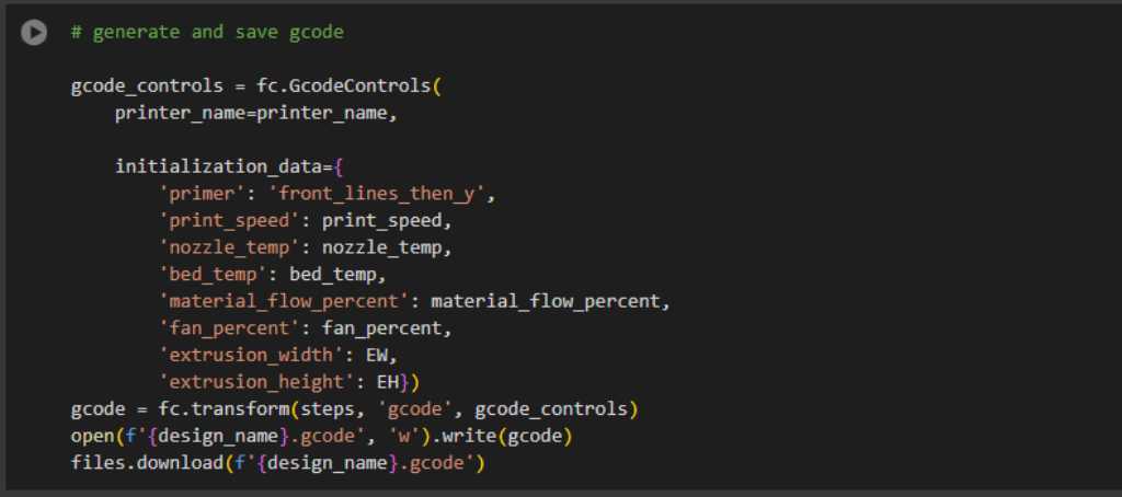
To get this code into GCode, the template has a section that does it for you. Just pressing the play button will get the GCode into a file that was ready to print:
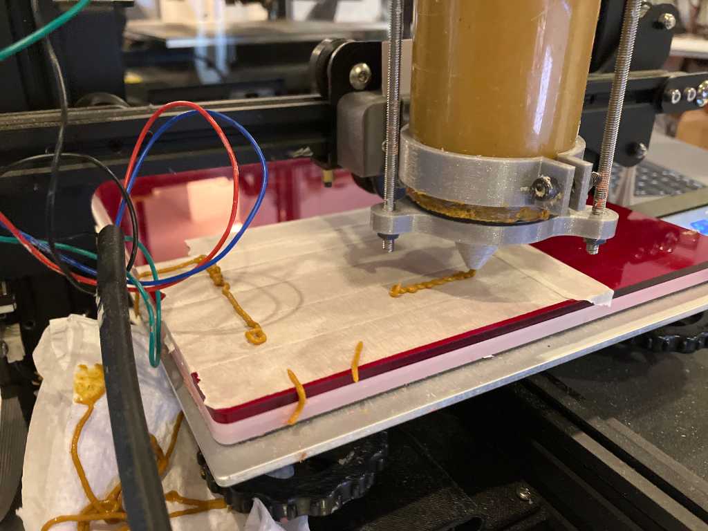
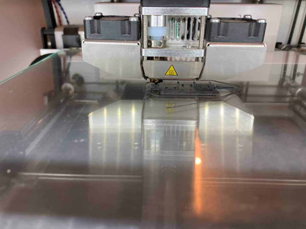
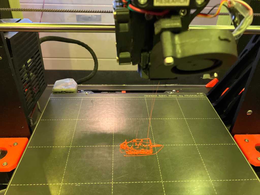
So this all seems quite a challange. I tried the above code on our Ultimaker 2+ and, well let’s say, it does need more tweaking…
But after a bit of tweaking the 2nd attempt actually looks a bit like the thing I designed. A little bit. Not too bad for a second attempt…
Some stuff I noticed and need to change:
the Z layers are too far apart. Looking at the code I told the machine to do 1mm per layer. So makes sense that it is too far apart. Need to find a way to reduce this.
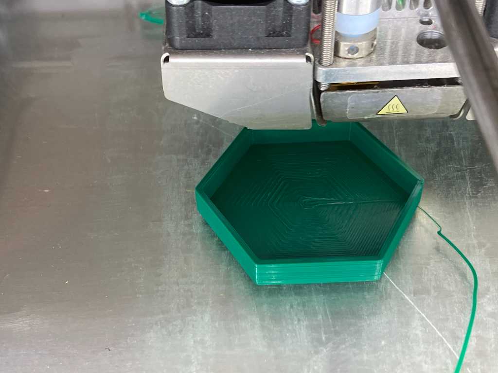
The bottom layer starts from the center. That failed but at a certain point it started to attach to the buildplate. I think it will be better to start from the outside and then work my way in.
Also the bottom layers are much too far apart. and all layers are just 1 line thick, so strength is not that great.
The droplets-making procedure does work. However, the droplets don’t fall to the bottom. They stick to the side. I think if I increase the droplet size, wait a bit longer for it to cool it might be better. Also, it might work better if I don’t knock them off using the side wall, but using the top layer (when not fully closed). This might act a a knife and gravity might help me.
The new version (for visibility reasons the top layer not simulated here):
After 12 iterations it finally starts to take shape as intended:
The roof overhang works really nice. I didn’t expect this. I this this is about 20 degrees angle!
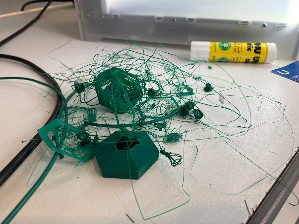
The granules-making still doesn’t work. It purges too much filament and is sticks to the side.
Lots of iterations later, it actually works! I changed locations (it now alternates between left and right knockoff), changed the extrusion speeds and some other stuff.
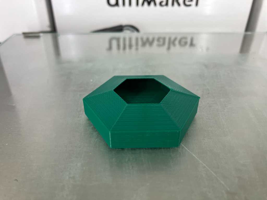
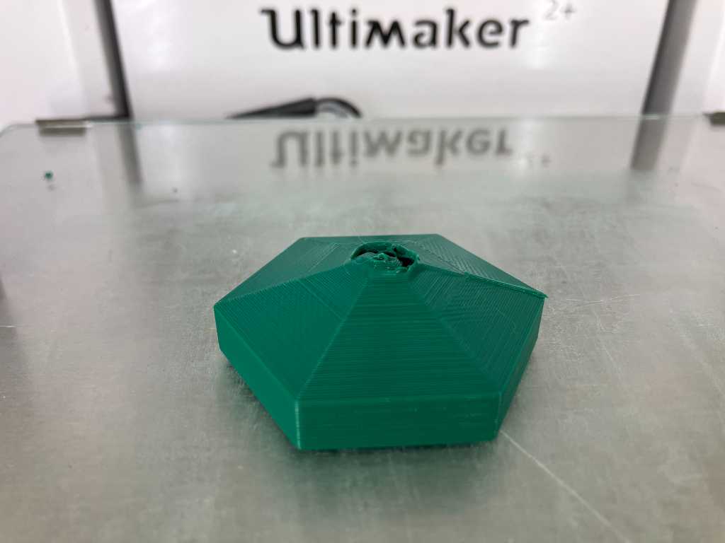
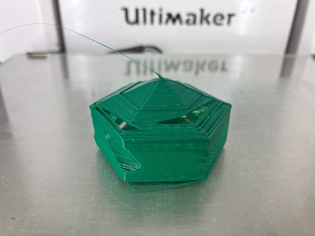
And so, lot’s of attempts later, I finally was able to create a 3D printed shaker!
So does it work?
The code (both the jupiter notebook as well as the gcode for Ultimaker 2+) is in my repo. See link below. The final code is here:
if 'google.colab' in str(get_ipython()):
  !pip install git+https://github.com/FullControlXYZ/fullcontrol --quiet
import fullcontrol as fc
from google.colab import files

# printer/gcode parameters
design_name = 'shaker'
nozzle_temp = 210
bed_temp = 60
print_speed = 1000
fan_percent = 100
material_flow_percent = 150
printer_name='ultimaker2plus' # generic / ultimaker2plus / prusa_i3 / ender_3 / cr_10 / bambulab_x1 / toolchanger_T0

# design parameters

EH = 0.2 # extrusion height (layer height is set to this value) - was 0.3
EW = 0.6 # extrusion width; recommended to be 1.5*nozzle_diameter - was 0.8
initial_z= EH*0.5 # initial nozzle position is set to a fraction of the extrusion height to get a bit of 'squish' for good bed adhesion
model_height = 7.5 # model height in mm (wall height, so excluding 2 bottom layers and the top layer)
layers = int(model_height / EH)

# generate the design (make sure you've run the above cells before running this cell)
initial_x = 100
initial_y = 100
radius = 25
circle_segments = 6
droplet_offset = 10
droplets = 60
droplet_volume = 0.8
droplet_speed = 50
bottom_circles_radius = fc.linspace(radius,0,round(radius/EW)) # calculate amount of circles required to properly fill the outer circle. going from outside to inside
wall_overlap = 0.8
top_layer_overlap = 0.6 # overlap layers so they don't fall down (lower = more overlap)


# initial steps
steps = []
steps.append(fc.Extruder(units='mm3'))  # set extrusion units to mm3 to make it easier to manually calculate E values
steps.append(fc.ExtrusionGeometry(area_model='rectangle', width = EW, height = EH))
steps.append(fc.Printer(print_speed=print_speed/2)) # halve print speed for the first layer
steps.append(fc.Extruder(on=False))
steps.append(fc.PrinterCommand(id='retract'))

# go to start position but don't go straight in order not to leave filament on the bed where printing needs to happen
steps.extend(fc.travel_to(fc.Point(x=initial_x + radius + 20, y=0, z=initial_z + 30)))
steps.extend(fc.travel_to(fc.Point(x=initial_x + radius + 20, y=initial_y, z=initial_z + 30)))
steps.append(fc.Extruder(on=True))
steps.append(fc.PrinterCommand(id='unretract'))


# bottom layer
for circle_position in range(round(radius/EW)):
  steps.extend(fc.circleXY(fc.Point(x=initial_x, y=initial_y, z=initial_z), bottom_circles_radius[circle_position], 0, circle_segments)) # add a circle with circle_segments
# bottom layer 2
steps.append(fc.Printer(print_speed=print_speed)) # normal print speed for the other layers
for circle_position in range(round(radius/EW)):
  steps.extend(fc.circleXY(fc.Point(x=initial_x, y=initial_y, z=initial_z+EH), bottom_circles_radius[circle_position], 0, circle_segments)) # add a circle with circle_segments


# wall
initial_wall_z = initial_z + 2 * EH
for layer in range(layers):
  steps.extend(fc.circleXY(fc.Point(x=initial_x, y=initial_y, z=initial_wall_z + layer * EH), radius, 0, circle_segments)) # add a circle with circle_segments
  steps.extend(fc.circleXY(fc.Point(x=initial_x, y=initial_y, z=initial_wall_z + layer * EH), radius-wall_overlap*EW, 0, circle_segments)) # add another circle using wall overlap


# partial top layer
top_layer_z = initial_wall_z + layers * EH
top_circles_radius = fc.linspace(radius,0,round(radius/(EW * top_layer_overlap))) # calculate amount of circles required to properly fill the outer circle. going from outside to inside
steps.extend(fc.travel_to(fc.Point(x=initial_x + radius, y=initial_y, z=top_layer_z)))
top_layers = round(radius/(EW * top_layer_overlap))
for circle_position in range(0, int(top_layers/2)): # first half of the top layers
  steps.extend(fc.circleXY(fc.Point(x=initial_x, y=initial_y, z=top_layer_z  + circle_position * (EH * top_layer_overlap)), top_circles_radius[circle_position], 0, circle_segments)) # add a circle with circle_segments


# granules
droplet_location_z = top_layer_z  + int(top_layers/2) * (EH * top_layer_overlap)
droplet_location = fc.Point(x=initial_x, y=initial_y, z=droplet_location_z)
droplet_purge_location = fc.Point(x=initial_x, y=initial_y, z=droplet_location_z)
droplet_purge_location_high = fc.Point(x=initial_x, y=initial_y, z=droplet_location_z + 20)
droplet_knockoff_location_left = fc.Point(x=initial_x - top_circles_radius[int(top_layers/2)] - droplet_offset, y=initial_y, z=droplet_location_z )
droplet_knockoff_location_high_left = fc.Point(x=initial_x - top_circles_radius[int(top_layers/2)] - droplet_offset, y=initial_y, z=droplet_location_z + 20 )
droplet_knockoff_location_right = fc.Point(x=initial_x + top_circles_radius[int(top_layers/2)] + droplet_offset, y=initial_y, z=droplet_location_z )
droplet_knockoff_location_high_right = fc.Point(x=initial_x + top_circles_radius[int(top_layers/2)] + droplet_offset, y=initial_y, z=droplet_location_z + 20 )

steps.extend(fc.travel_to(fc.Point(x=0, y=0, z=droplet_location_z + 20))) # travel up
steps.extend(fc.travel_to(fc.Point(x=initial_x - top_circles_radius[int(top_layers/2)] - droplet_offset, y=initial_y, z=droplet_location_z + 20))) # travel to high above dropletlocation
steps.extend(fc.travel_to(droplet_purge_location_high)) # travel to purge location
steps.append(fc.Extruder(on=True))
steps.append(fc.PrinterCommand(id='unretract'))

for droplet in range(droplets):
  steps.append(fc.StationaryExtrusion(volume=droplet_volume, speed=droplet_speed)) # stationary extrude droplet_volume mm^3 with speed of droplet_speed.
  steps.append(fc.ManualGcode(text='G4 P5000')) # add GCode to wait.
# not sure what to use to retract properly: negative extrusion? Or printerCommand id retract? And should the last one be followed by unretract as well?
#  steps.append(fc.StationaryExtrusion(volume=-1, speed=50)) # stationary negatively extrude 1mm^3 with speed of 50 (is tris retraction?).
  steps.append(fc.Extruder(on=False))
  steps.append(fc.PrinterCommand(id='retract'))
  steps.append(fc.ManualGcode(text='G4 P2000')) # add GCode to wait.
  steps.extend(fc.travel_to(droplet_purge_location)) # travel down
  if (droplet % 2): # go left for uneven num droplets, go right for even num droplets
    steps.extend(fc.travel_to(droplet_knockoff_location_left)) # travel across the wall of the circle to knock off the filament droplet
    steps.extend(fc.travel_to(droplet_knockoff_location_high_left)) # travel across the wall of the circle to knock off the filament droplet
  else:
    steps.extend(fc.travel_to(droplet_knockoff_location_right)) # travel across the wall of the circle to knock off the filament droplet
    steps.extend(fc.travel_to(droplet_knockoff_location_high_right)) # travel across the wall of the circle to knock off the filament droplet
  steps.extend(fc.travel_to(droplet_purge_location_high)) # go back
  steps.append(fc.Extruder(on=True))
  steps.append(fc.PrinterCommand(id='unretract'))

# # some labels for explanation in the plot
# steps.append(fc.PlotAnnotation(label='extrude 2mm^3 here and wait 1s',point=droplet_location))
# for droplet in range(droplets):
#   steps.append(fc.PlotAnnotation(label='knock off droplet ' + str(droplet),point=fc.Point(x=initial_x - top_circles_radius[int(top_layers/2)] - droplet_offset, y=initial_y, z=droplet_location_z - droplet)))


# remainder of the top layer
steps.extend(fc.travel_to(fc.Point(x=0, y=0, z=initial_z + 70)))
steps.extend(fc.travel_to(fc.Point(x=initial_x + radius, y=initial_y, z=initial_z + 70)))
steps.extend(fc.travel_to(fc.Point(x=initial_x + radius, y=initial_y, z=top_layer_z)))

steps.append(fc.Printer(print_speed=print_speed/2)) # halve print speed for the final part

for circle_position in range(int(top_layers/2), top_layers): # second half of the top layers
  steps.extend(fc.circleXY(fc.Point(x=initial_x, y=initial_y, z=top_layer_z  + circle_position * (EH * top_layer_overlap)), top_circles_radius[circle_position], 0, circle_segments)) # add a circle with circle_segments

fc.transform(steps, 'plot', fc.PlotControls(zoom=0.7, color_type='print_sequence_fluctuating')) # show as extrusion
#fc.transform(steps, 'plot', fc.PlotControls(style='line', zoom=0.7, color_type='print_sequence_fluctuating')) # show as line
#print(fc.transform(steps, 'gcode'))


# generate and save gcode
gcode_controls = fc.GcodeControls(
    printer_name=printer_name,

    initialization_data={
        'primer': 'front_lines_then_y',
        'print_speed': print_speed,
        'nozzle_temp': nozzle_temp,
        'bed_temp': bed_temp,
        'material_flow_percent': material_flow_percent,
        'fan_percent': fan_percent,
        'extrusion_width': EW,
        'extrusion_height': EH})
gcode = fc.transform(steps, 'gcode', gcode_controls)
open(f'{design_name}.gcode', 'w').write(gcode)
files.download(f'{design_name}.gcode')
3D scanning
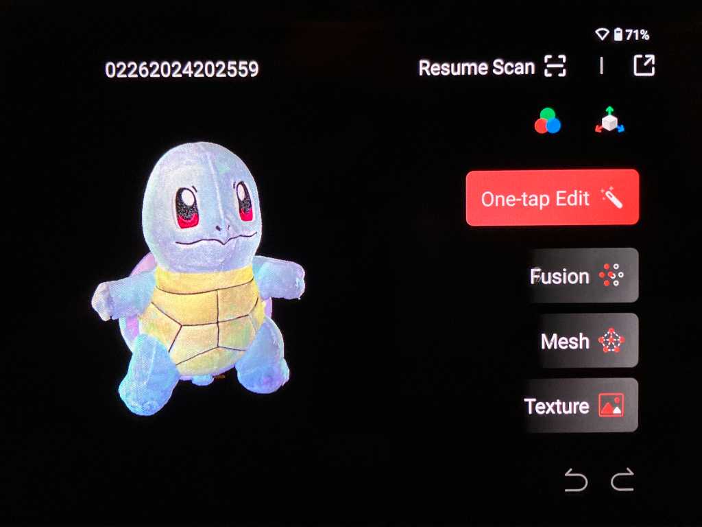
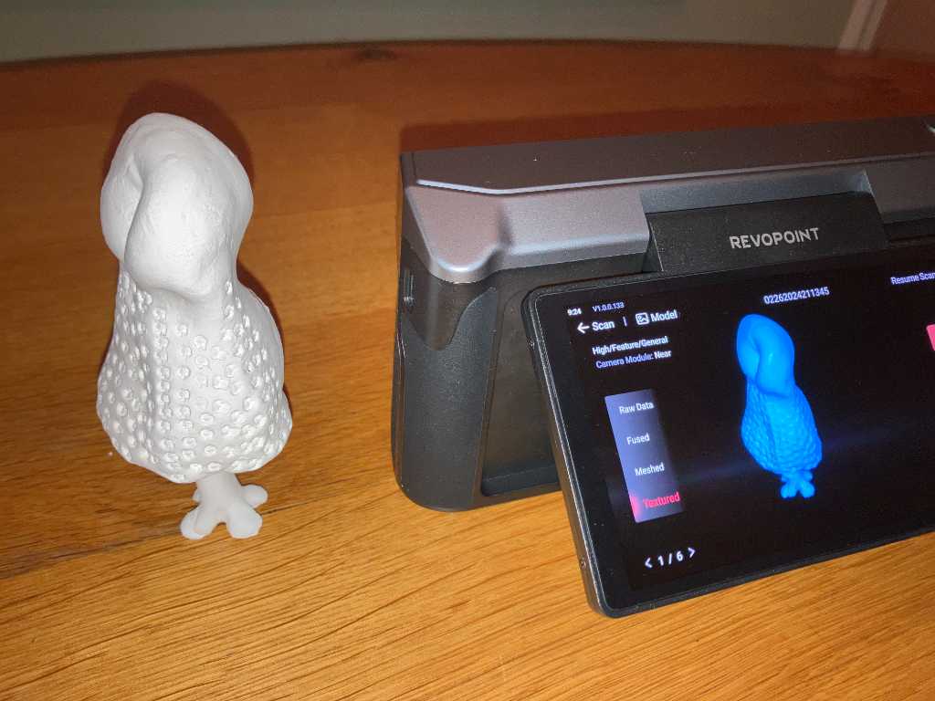
I’m scanning a plush toy of my son. I’m using the 3D scanner that we just bought: a Revopoint Miraco Pro. It goes up to 0.02mm precision with 0.05mm accuracy.
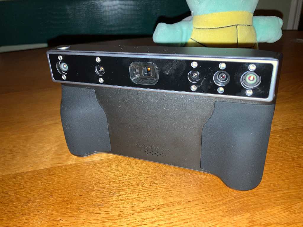
I have it set to “near” mode and used its flashlight for increased light on the plush toy.
The scanner has 2 modes: single shot, where you take multiple pictures of your model, or continuous. This is more like taking a video.
Important to note: repeated scanning makes your model worse. One scan close to the object will result in the best accuracy.
The minimum scan volume is 10mm x 10mm x 10mm. And similar to most 3D scanners, it may have difficulty with highly reflective or transparent objects.
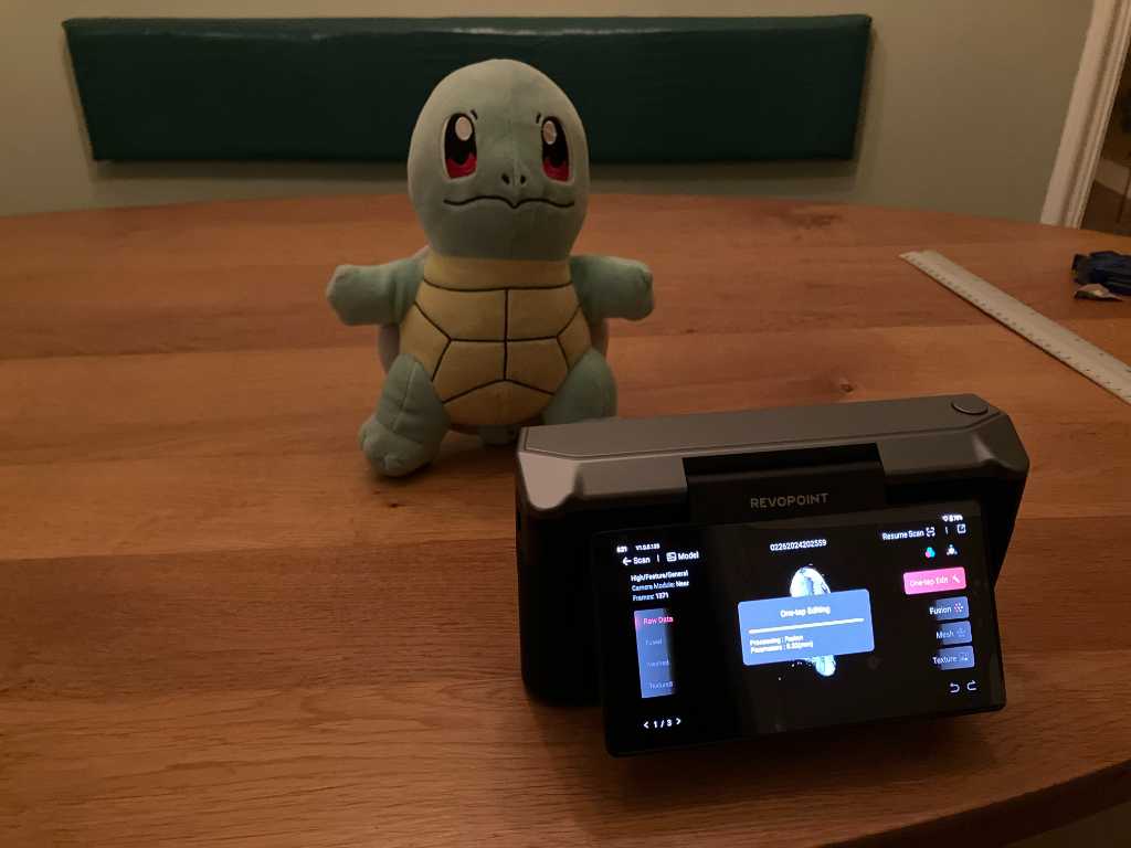
Post-processing is done on the scanner using its build-in touchscreen. You can edit (remove unwanted points), fuse and create a mesh. I used the in-screen one-tap edit which does fusing and meshing and texturing. You can do these operations one by one as well and it will provide you with more options if you do manually.
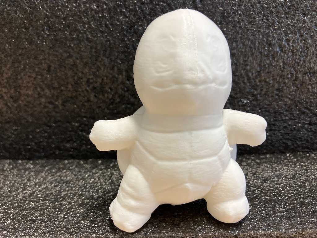
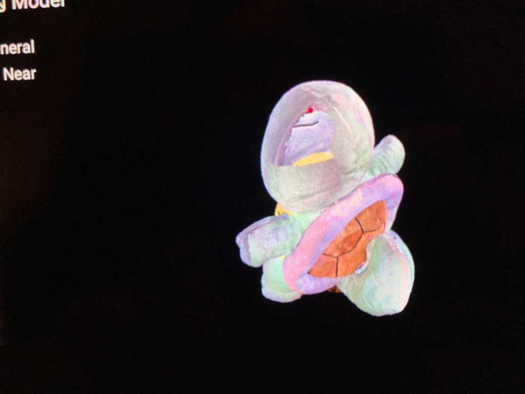
That came out great! It only missed a spot at the back of the head so you can see-through:
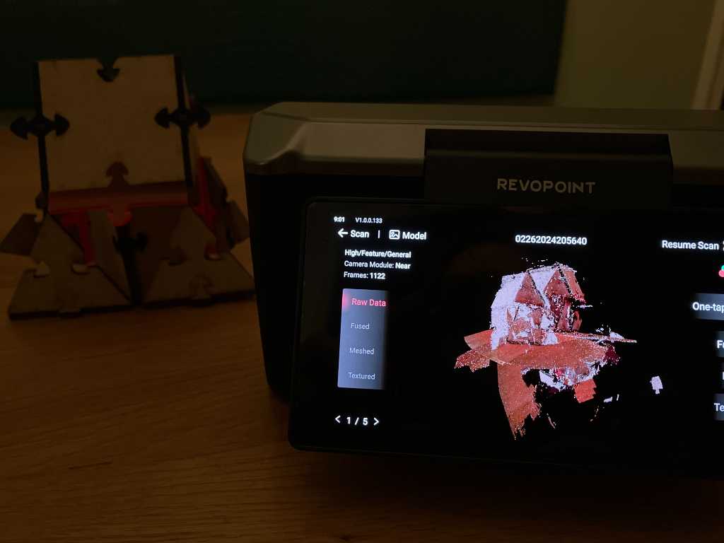
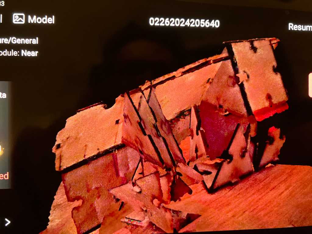
Another model that I scanned (tuQ, which I made during computer-controlled cutting week) was much more of an issue. Bad lighting, wooden model on a wooden table, too many flat surfaces with repeating patterns, the scanner couldn’t deal with it:
One more then. 3D scanners like organic models. So here’s one made of clay:
So now we’re done on the scanner. Next is to upload the scan to my computer. I’ve installed Revoscan 5 software and both scanner and laptop are on the same wifi network. From the docs:
Revo Scan is the companion scanning software for the Integrates model scanning, post-processing, and multi-model alignment functionalities, empowering you to effortlessly accomplish 3D modeling tasks.
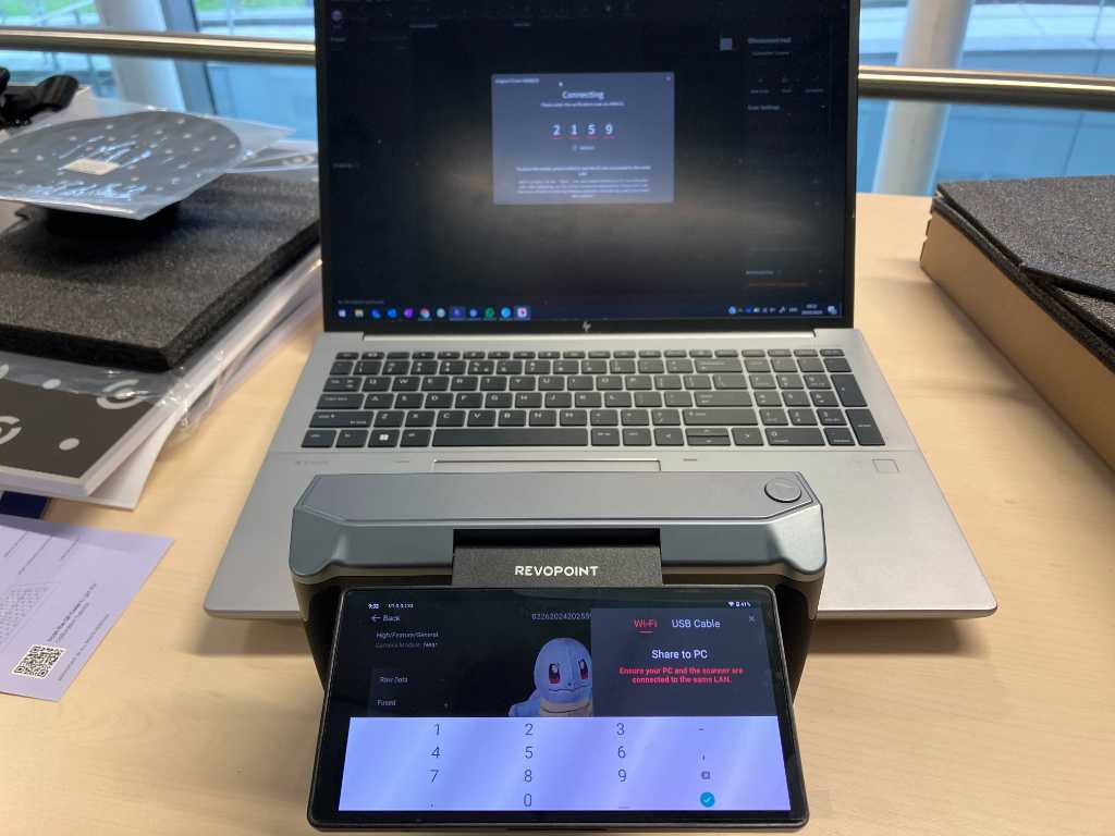
The scan of the plush toy is a whopping 4GB. So transfer will take some time. I don’t want to do that over WiFi so I’m connecting the scanner using usb-c. This way it’ll only take 2 minutes. After transfer I found out that the scanner puts scans into projects. All my scans are in the same project and you can only transfer the full project. So that’s why the file was this big.
By the way, connecting the Miraco using USB-C also allows you to use the scanner in PC mode where the scanner is controlled using the pc software and scan data is stored on the pc immediately. This will give you much easier control over all settings and I think this would be preferred if you use the scanner for small objects, statically or using the turntable.
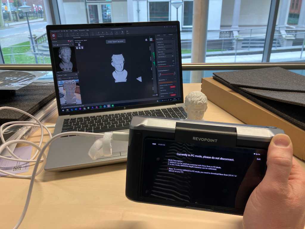
When the model is on the PC you can edit it. For example there’s a “fill holes” menu item that detects holes in the scan and fixes them. Sort of a solidify command.
After edit you can save the mesh as ply, obj or stl file using the export menu item. If you want you can also save the pointcloud and the textures.
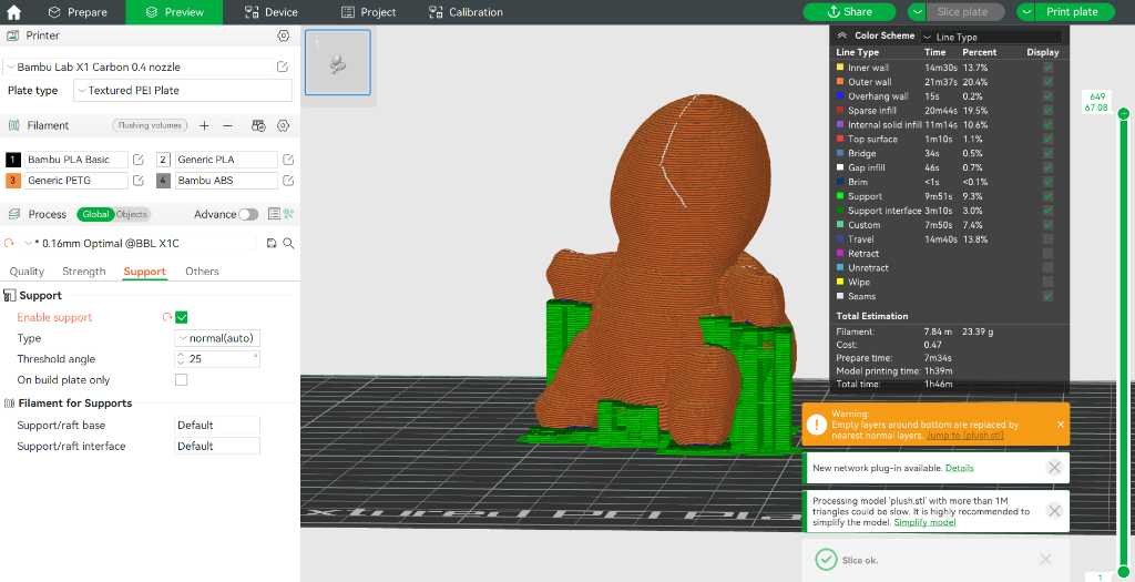
So I saved it as STL, imported it in Bambu Studio and going to print it in PLA white. Of course scaled down to 30%.
Link to repo
What I learned this week
Successes
Fullcontrol GCode is very nice. Being able to work directly in GCode made me feel more knowledgable about the 3D printer. Without doing this, 3D printing is like: make design, slice, print and drink coffee while waiting for the result. Now I was sitting next to the machine and for every part I knew what it was doing and why. So that was great fun!
I also had fun printing lots of bengines. I never printed with PETG and with ABS before. PETG is a keeper. ABS not, due to toxic smells, rough edges, less-forgiving. But for the majority of 3D prints, I’ll stick to PLA.
In terms of 3D scanning, it was interesting to use our new Revopoint Miraco Pro. It’s very easy to get to a good scan. Although I had a hard time identifying missing parts on the touchscreen of the Miraco. All edits should be done on the Miraco itself. It’s quite easy, but precision editing is challenging. Also I did not find a “solidify” option. So directly 3D printing your scan is no option.
Fails & Fixes
Lot’s of fails this week. The biggest one: Clean your bed. Always clean your bed. Never assume somebody else did it for you.
Remember this for next time
Did I mention you should always clean your bed?