alternative connections to SPI on SAMD
Note: this text is a direct copy of http://www.stowlake.com/SPIStories/SPIOnD21.html. It’s just here to make sure this great information will never go away. All copyright, if any, and all other stuff remains there.
Note 2: the information below is applicable to all SAMD microcontrollers. Including the SAMD11C14.
SPI choices for D21-based Arduino boards
On Arduino models with the Atmel SAMD21G18A(D21 for short) processor such as the Tian and the M0 Pro, it is possible to implement Serial Peripheral Interface(SPI) protocol on any of several different combinations of Arduino pins. On those models, the SPIClass class in the Arduino libraries supports a SPI bus over the ICSP connector as it does on other Arduino models. But that processor has circuits to support several SPI buses. You can write a subclass of SPIClass. In that class, you can configure your own SPI bus to use a different set of digital pins for an SPI bus.
To do this, you need to learn a little about what is inside the D21
Hardware
The D21
Inside this ARM processor is a collection of configurable peripheral interface devices. The D21 Datasheet describes the chip in great detail. It is the source for information in this document.
Connecting to the D21
The signals follow this path from connected SPI device to program running on the D21:
- from Arduino pins to processor pins
- from processor pins to multiplexors
- from multiplexors to SERCOM pads
- from SERCOM pads to SPI roles
The sections below follow this path in more detail.
Processor Pins, Arduino Pins
D21 processor pins are labeled A00 through A31 and B00 through B31. On the Arduino boards, I/O pins D0 through D13 and A0 through A5, SDA and SCL are each connected to a processor pin.
Serial Communications Interfaces
A Serial Communications Interface(a SERCOM) is a circuit inside the D21 for serial communications. Each SERCOM can be configured to support one of several different serial protocols such as USART, SPI and I2C. There are six SERCOMs : SERCOM0, …, SERCOM5. Each of them has four signal lines called PAD[0], PAD[1], PAD[2], PAD[3].
Some of the serial interfaces are already assigned to Serial, Serial5 and SPI classes. Those are SERCOM0, SERCOM5 and SERCOM4. This leaves SERCOM1, SERCOM2, and SERCOM3 available for SPI–as long as you don’t need those serial interfaces to support other serial protocols.
A sketch can configure the mapping between the SPI signals: MISO, MOSI, SCK, _SS and the SERCOM lines: PAD[0], PAD[1], PAD[2], PAD[3] within limits.
Multiplexing
Each of the processor pins can be configured to perform one of many possible functions. A pin is assigned to a function named with a single letter A through H. These are described in the datasheet in the chapter on multiplexing. Functions C and D are of interest here because they are used to connect to SERCOMs. The table shows the connections for functions C and D for the processor pins that are connected to Arduino pins.
A program assigns one of these functions to a pin. When it assigns function D to pin D2, the pin becomes, effectively, a connection to the PAD[0] of SERCOM2 as you can see in this table.
| Arduino | Processor | C |
D |
||
| Pin | Pin | SERCOM | SERCOM_ALT | ||
| D0 | PA11 | SERCOM0 |
PAD[3] |
SERCOM2 |
PAD[3] |
| D1 | PA10 | SERCOM0 |
PAD[2] |
SERCOM2 |
PAD[2] |
| D2 | PA08 | SERCOM0 |
PAD[0] |
SERCOM2 |
PAD[0] |
| D3 | PA09 | SERCOM0 |
PAD[1] |
SERCOM2 |
PAD[1] |
| D4 | PA14 | SERCOM2 |
PAD[2] |
SERCOM4 |
PAD[2] |
| D5 | PA15 | SERCOM2 |
PAD[3] |
SERCOM4 |
PAD[3] |
| D6 | PA20 | SERCOM5 |
PAD[2] |
SERCOM3 |
PAD[2] |
| D7 | PA21 | SERCOM5 |
PAD[3] |
SERCOM3 |
PAD[3] |
| D8 | PA06 | SERCOM0 |
PAD[2] |
||
| D9 | PA07 | SERCOM0 |
PAD[3] |
||
| D10 | PA18 | SERCOM1 |
PAD[2] |
SERCOM3 |
PAD[2] |
| D11 | PA16 | SERCOM1 |
PAD[0] |
SERCOM3 |
PAD[0] |
| D12 | PA19 | SERCOM1 |
PAD[3] |
SERCOM3 |
PAD[3] |
| D13 | PA17 | SERCOM1 |
PAD[1] |
SERCOM3 |
PAD[1] |
| A0 | PA02 | ||||
| A1 | PB08 | SERCOM4 |
PAD[0] |
||
| A2 | PB09 | SERCOM4 |
PAD[1] |
||
| A3 | PA04 | SERCOM0 |
PAD[0] |
||
| A4 | PA05 | SERCOM0 |
PAD[1] |
||
| A5 | PB02 | SERCOM5 |
PAD[0] |
||
| SDA | PA22 | SERCOM3 |
PAD[0] |
SERCOM5 |
PAD[0] |
| SCL | PA23 | SERCOM3 |
PAD[1] |
SERCOM5 |
PAD[1] |
Software
Libraries
There are a few library files that you need to look at to follow how the example works:
- /Applications/Arduino-1.7.10.app/Contents/Java/hardware/arduino/samd/libraries/SPI/SPI.h
- /Applications/Arduino-1.7.10.app/Contents/Java/hardware/arduino/samd/cores/arduino/SERCOM.h
- /Applications/Arduino-1.7.10.app/Contents/Java/hardware/arduino/samd/cores/arduino/SERCOM.cpp
- /Applications/Arduino-1.7.10.app/Contents/Java/hardware/arduino/samd/variants/arduino_zero/variant.h
- /Applications/Arduino-1.7.10.app/Contents/Java/hardware/arduino/samd/variants/arduino_zero/variant.cpp
- /Applications/Arduino-1.7.10.app/Contents/Java/hardware/arduino/sam/system/libsam/include/pio.h
These paths are typical for Macintosh. Note that, in order to see the files in the finder, you need to right click on the application and select Show Package Contents.
Pin assignments
In the example, Arduino pins are assigned to custom SPI roles:
- SDA - MOSI
- SCL - SCK
- D10 - SS
- D7 - MISO
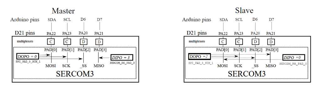
The choice of pins and signals is entirely arbitrary within limits. This figure shows the target configuration.
Multiplexers
In the multiplexing table above, we can see that our goal can be reached. In the row for Arduino pin D7, in the SERCOM-ALT column, D, is SERCOM3, PAD[3]. When software assigns function D to that pin, it makes a connection to the pad of SERCOM3.
DOPO and DIPO
Data out pinout and data in pinout. These are fields in hardware control registers. A sketch can set the values when initializing a SERCOM.
For SPI Main, possible DOPO values are:
SPI_PAD_0_SCK_1MOSI=PAD[0], SCK=PAD[1]SPI_PAD_2_SCK_3MOSI=PAD[2], SCK=PAD[3]SPI_PAD_3_SCK_1MOSI=PAD[3], SCK=PAD[1]SPI_PAD_0_SCK_3MOSI=PAD[0], SCK=PAD[3]
For SPI Main, possible DIPO values are:
SERCOM_RX_PAD_0MISO=PAD[0]SERCOM_RX_PAD_1MISO=PAD[1]SERCOM_RX_PAD_2MISO=PAD[2]SERCOM_RX_PAD_3MISO=PAD[3]
Example sketch Sketches have been run on Arduino IDE 1.7.11. When this sketch is loaded, the user can enter a command to tell the sketch to send a short text message to the slave. The sketch displays the response from the slave in the Serial Monitor.
To send and receive a message, the sketch will:
- turn on SPI
- set _SS to LOW(active)
- using a library function send and receive bytes one at a time
- shut down SPI
- set _SS to HIGH(inactive)/li>
- write the data received from the slave onto the serial port
Before running the sketch, the SPI pins should be connected to another SPI device configured as slave. Don’t forget to attach GND as well.
Moving on to your own SPI bus
To build your own custom SPI connections on the Tian or other Arduino based on a SAMD21 processor:
- Decide which pins are available.
- Choose a SERCOM that connects to three of those pins for
MISO,MOSIandSCK. - Choose a pin for
_SS. - Decide which of the SERCOM connections will be used for which SPI connection
- Once you have determined a configuration that works, you can replace the values in the sample sketch to run it.
Available pins
Consider the other requirements for your sketch. Which pins do you need? Which pins are take by other uses such as serial for the console?
Choose a SERCOM
Given the available pins, search the table in the multiplexing section above for a SERCOM device. It should be one that isn’t already in use and connects to at least 3 of the pins that are available. Use this information to setup a MySpiPadSet structure like the one in the sample sketch. The MySpiPadSet and sercom device are parameters for a MySPI constructor.
A pin for _SS
It is your master mode program that will control the _SS output. The MySpiPadSet structure in MySpi.h includes an member for slave select. This is not used in this example but included for future expansion of MySPI. The digital pin that you use for _SS does not need to be connected to a SERCOM.
Connections between SERCOM and SPI signals
The choices for which of the SERCOM connections, PAD[0] through PAD[3] are listed in the section above on DIPO and DIPI[0]. These values are passed as parameters to begin() in MySPI class.
Go
The software configuration is complete ready to run.