input devices
Topic(s) of this week
- input devices (video, review)
- Demonstrate workflows used in sensing something with input device(s) and MCU board
Hero shots
Assignments
Group assignment
- Probe an input device(s)’s analog levels and digital signals
- Document your work on the group work page and reflect on your individual page what you learned
Individual assignment
- Measure something: add a sensor to a microcontroller board that you have designed and read it.
What I think I already know
With my media engineering background I’m quite confident to say that I know enough about this subject to get through the week without brain meltdown :-)
What I want to learn
I want to get the pressure sensors of my final project up & running. That’s my main goal of this week. So milling my sensor PCB and programmmmm!
SSTM planning
Supply
| Day | Supply | Tasks |
|---|---|---|
| Thursday | 08:00-09:30 (train) | main PCB design |
| 10:00-18:00 | group assignment | |
| Friday | 9:00-13:00 (fablab) | Mill and solder sensor PCB |
| solder sensor flex PCB | ||
| cast sensor | ||
| Saturday | Program sensor PCB | |
| Sunday | Program sensor PCB | |
| Monday | 9:00-17:30 (fablab) | More soldering, casting, etc |
| 19:00-23:00 | programming | |
| Tuesday | 9:00-17:30 (fablab) | even more of the above :-) |
| Wednesday | 9:00-12:00 (fablab) | |
| 12:00-13:00 | Local review | |
| 13:00-14:00 | Regional review | |
| 15:00-18:00 | Neil time |
Tasks
Have you answered these questions?
- Documented what you learned from interfacing an input device(s) to your microcontroller and optionally, how the physical property relates to the measured results.
- Documented your design and fabrication process or linked to the board you made in a previous assignment.
- Explained the programming process(es) you used.
- Explained any problems you encountered and how you fixed them.
- Included original design files and source code.
- Included a ‘hero shot’ of your board.
- Leave feedback in Nueval that this weekly is ready for evaluation.
WAAG session and group assignment
Erwin gave us a presentation on input devices.
There are 2 different types of signals to measure: analog values and digital values (on and off).
Analog values come in the form of capacitance, resistance or current/voltage. They need to be sampled. The microcontroller will then convert it to digital values using a built-in ADC (analog-to-digital-converter).
An ADC has a certain precision: 8 bit (255 values), 10 bit (1023 values), 12 bit (4095 values), etc. More bits is more precision. ADCs are generally made using a lot of comparators.
If you only have small voltage changes to measure, you can use a wheatstone bridge to measure it. It acts similar to a balanced weighing scale. It’ll give much more accuracy, even with low resolution ADC. In a wheatstone bridge 3 resistors are fixed and equal and one resistor (your sensor) is variable.
Digital values are read using the GPIO pins. To make sure the input values are defined, you use a pullup resistor (can be external, but usually microcontrollers have internal pullups as well). You can also use pulldown resistors but pullup is a bit more energy efficient.
Sensors can also be equipped with a digital communication bus like 1-wire, I2C, SPI, Serial (UART), PWM, etc.
Famous examples:
- 1 wire -> DS18D20 temperature sensor (has a hardcoded 64-bit identifier)
- I2C -> PCA9555 I/O expander, BME280 temperature/humidity sensor, VL51L0X laser time-of-flight distance sensor
- SPI (MISO - MOSI Msin/Secondary or CIPO - POCI controller/peripheral) -> DS1302 Real Time Clock, BME280 temp/hum sensor, flash memory/SD cards
- UART -> US-100 ultrasonic distance sensor, NEO-8M GPS receiver, MG-Z19B CO2 concentration
- PWM -> microcontroller will have to measure the duty cycle. -> Radio control signals, IR remote control sensor
Measuring sensors
DHT11 temperature / humidity sensor
We’re going to use a DHT11 temperature/humidity sensor.
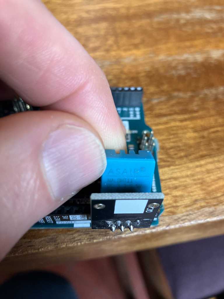
Pinout of the PCB that has this sensor (note this is not the pinout of the sensor itself!):
- SIGNAL
- VCC
- GND
The data pin is spitting out data in a single-wire bidirectional communication protocol.
We connect it to an Arduino Uno. As the We’re going to use:
Signal -> D7
VCC -> D6
GND -> D5
So we’re connecting VCC and GND to GPIOs as well and set them to have pullups and pulldowns. That way we provide power to the sensor. And as the sensor isn’t really power-hungry, this should work fine.
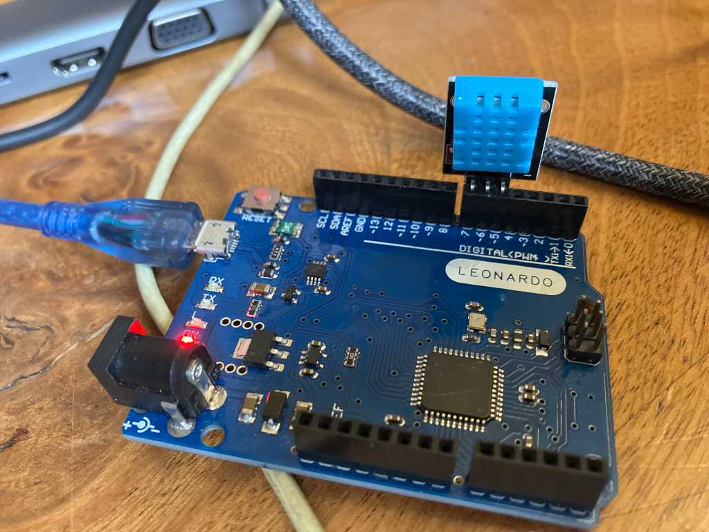
And it works!
The communication bits look like this on the oscilloscope:
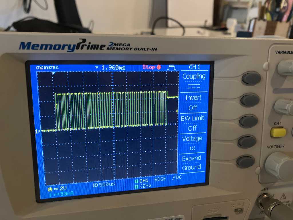
Code and some more documentation on this is on the site of Joe Wallace.
503 linear hall effect sensor
Next is to try an analog sensor. We chose the hall effect sensors. Please note there are 2 different types: a switching hall effect sensor like the 3144 and a linear hall effect sensor like the HAL503. We’re going to use the latter.
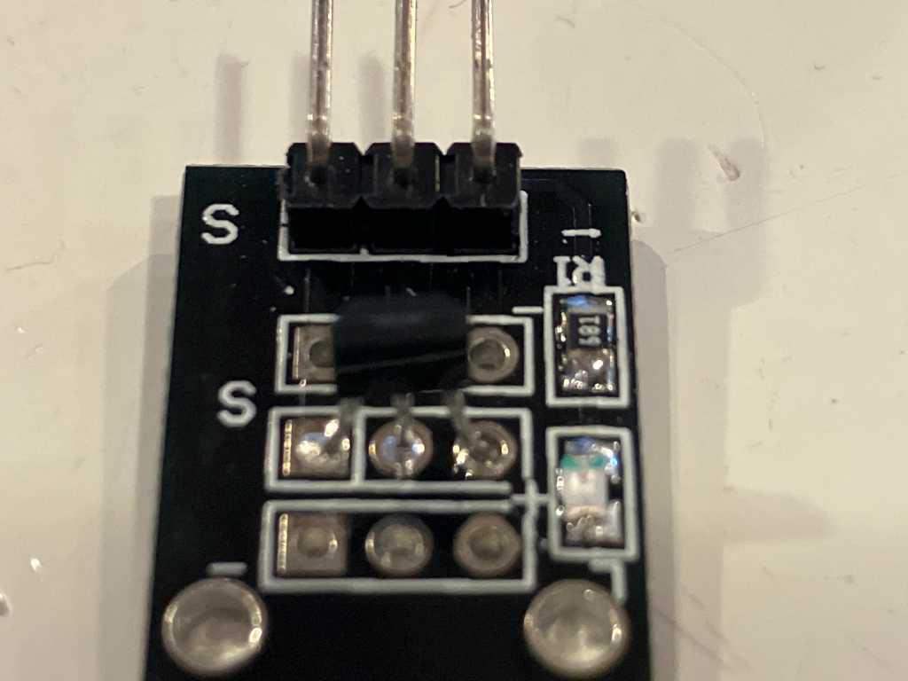
Pinout of the PCB with the sensor:
- SIGNAL
- VCC
- GND
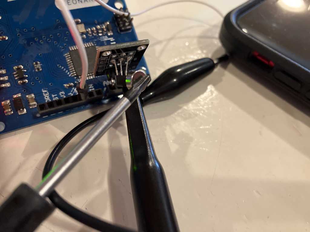
We attached the sensor to the analog pins of the leonardo, because the signal output is an analog value. So:
- SIGNAL -> A2
- VCC -> A1
- GND -> A0
Next we programmed this piece of code:
// linear hall effect sensor example

const int sensorGND = A0;
const int sensorVCC = A1;
const int sensorDATA = A2;

void setup() {
  // put your setup code here, to run once:
  pinMode(sensorGND, OUTPUT);
  digitalWrite(sensorGND, LOW);
  pinMode(sensorVCC, OUTPUT);
  digitalWrite(sensorVCC, HIGH);
  Serial.begin(115200);
}

void loop() {
  // put your main code here, to run repeatedly:
  int sensorValue = analogRead(sensorDATA);
  Serial.print("Sensorvalue = ");
  Serial.println(sensorValue);
  delay(20);
}
We’re using a small magnet to check the sensor:
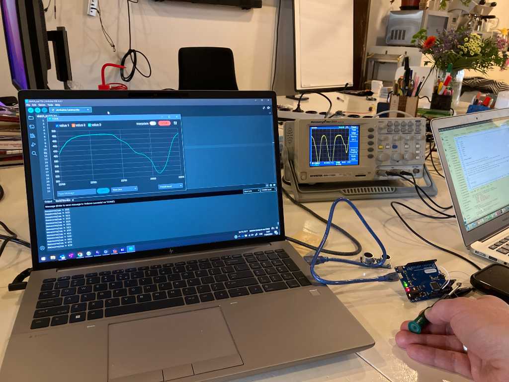
And here’s the result! Note the oscilloscope in the back doing the same thing (it is connected directly to the Sensor output, timebase is set differently though):
Individual assignment
In my individual assignment I’m going to work on the pressure sensors that I want to use in my final project. I’m going to make the sensors myself.
All documentation is in the following pages of my final project (to keep things together).
The creation of the SAMD PCB with 20 analog inputs is here.
So here are only some images for reference:
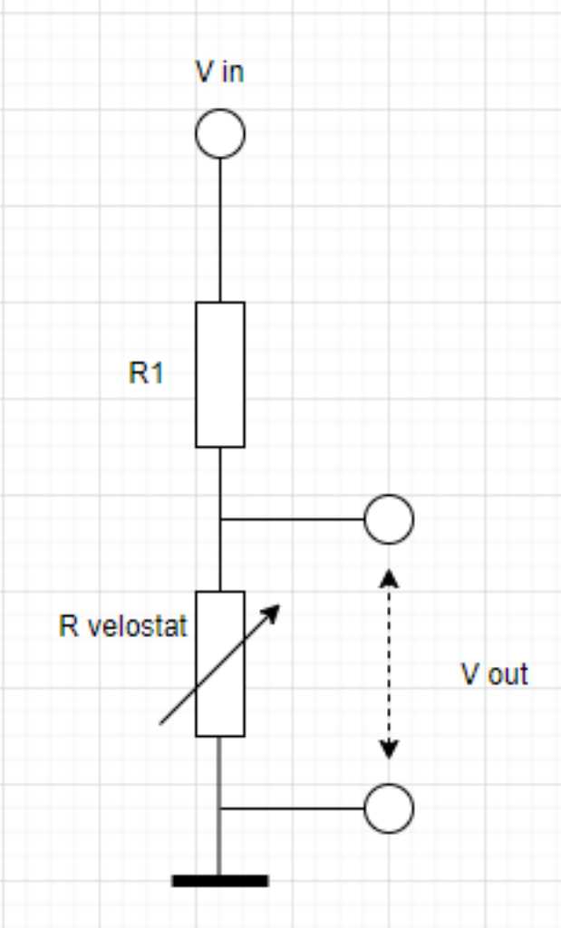
Sensor schematic where the ADC is going to measure Vout.
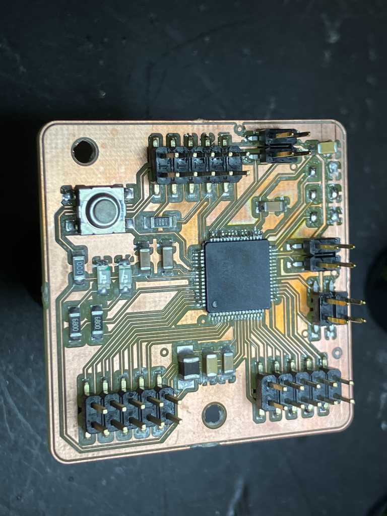
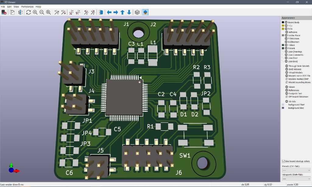
Sensor module board with SAMD21J18A (64 pin TQFP package). Render and actual milled version:
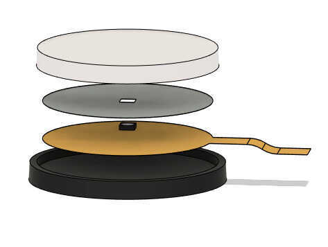
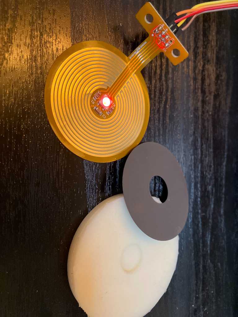
Force sensitive resistor (FSR) sensor casted out of polyurethane. Render and actual version:
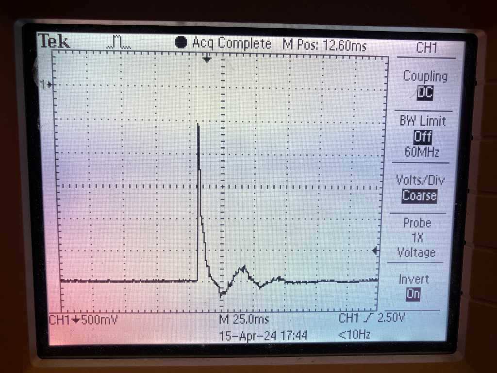
Oscilloscope screenshot of 1 single hit of a mallet stick on this FSR sensor:
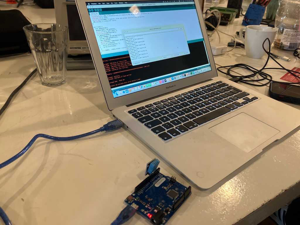
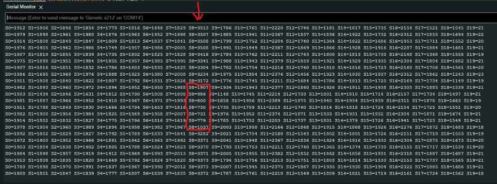
I programmed the microcontroller to capture all 20 ADC inputs and show their values in serial monitor.
Here is a screenshot of the serial monitor with 1 sensor attached to input 8. The ADC is set to 12 bit so the maximum value is 4095. Without the graphite sprayed PET circle (no conductance at all), the output varies between 4085 and 4095. With the PET circle and the top sensor part the output is around 3870 (this is because there is a bit of conductance due to the graphite and a bit of pressure due to the weight of the sensor top part).
When pressing, the measured value goes down into the 700’s.
in V2 of my program I’ve added hit detection by detecting local minimum value. The result is here:
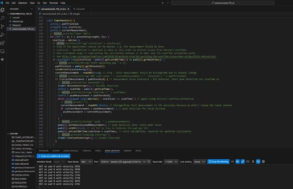
Note that the actual velocity level is not accurate enough. I need to work on the ADC sampling speed and optimize my code to make it faster so it can accurately capture the peak.
Link to repo
The sensor module (20 analog inputs on a SAMD21J18)
The firmware of the sensor module
What I learned this week
Successes
I managed to get my sensor board PCB to work! That 64 pin TQFP was a challange. But I can now measure 20 sensors :D
A lot of this week was programming to get the ADC of the microcontroller to behave nicely. It’s starting to get there, but not done yet.