11. Input Devices
Group assignment:
- Probe an input device(s)'s analog levels and digital signals
- Document your work on the group work page and reflect on your individual page what you learned
Learning outcomes
- Demonstrate workflows used in sensing something with input device(s) and MCU board
| Day | Supply | Tasks | |
|---|---|---|---|
| Thursday | 10:00-13:00 | Lecture from Erwin | [x] |
| 14:00-18:00 | Group assignment | [x] | |
| Friday | 09:00-11:30 | Catch up on CNC (Prep files for CNC) | [x] |
| 11:30-12:00 | Call with Physio | [x] | |
| 13:00-17:00 | Shotbot, sanding and fixing | [x] | |
| Saturday | 09:00-12:00 | Electronics design | [x] |
| Sunday | 09:00-12:00 | Final project planning | [x] |
| Monday | 9:00-17:30 | PCB milling | [x] |
| Soldering, coding, testing | [x] | ||
| 20:00-23:00 | Documentation | [x] | |
| Tuesday | 9:00-17:30 | Last bits on inputs if required | [x] |
| Final project design | [] | ||
| 20:00-22:00 | Documentation | [x] | |
| Wednesday | 9:00-11:00 | Documentation | [x] |
Class Notes
Input -> system -> Output
Two types
Analog
- the physical units is converted to a resistance, capacitance or current (then to voltage)
- values are sampled (taken over time)
- signals can be amplified
Digital
- the physical unit is converted in opening or closing a circuit
interfaces
- analog to digital converter
- voltage to value
- 8-bit,10-bit,12..16 more bits more resolution
8 bit = max value of 255 10 bit = max value 1024(1023 counting from 0)
so we if we have 5 volt vcc we with an 8 bit input, we can divide the voltage by 255 and measure at 0.004v?
Interface - GPIO
-Low 0-1-3v -Hight 3-5V
Interface - Protocol
1 wire/ TWI
- DHT temp sensor
I2C
- invented by philips for communication inside of a tv
- 7 bit address for IC, most of them fixed
- Nobody stopping you making your own address famous i2c PCA955 I/O expander BME280 Temp.hum VL51L0X Laser distance
SPI
- Invented by Motorola
- Exchange of bits between master - slave (MISO - MOSI)
- Use chip select (CS) to specify which slave tot talk to Famous
Serial
- UART
- RX/TX with a baudrate Famous US-100 ultrasonic distance NEO-8M GPS receiver MH-Z19B CO2 concentration
PWM
- Duty cycle
- For use in EMC-noisy environments
UNITS
Volts = kgm2S-3A-1 (OR (kg * m2)/(s3A))
SI system - Seconds - Meters - Kilograms - Ampere - Kelvin - Mole - Candela
Group assignment:
- Probe an input device(s)'s analog levels and digital signals
- Document your work on the group work page and reflect on your individual page what you learned
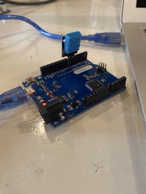
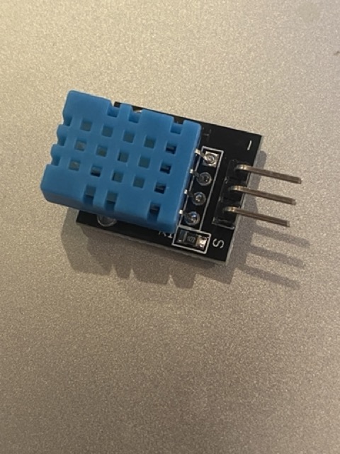
For the group assignment, luckily for me, the guys decided to play with a DHT11 Temp/Humidity sensor connected to an Arduino Leonardo board. Reading the data sheet we discovered it is a single wire protocol sending data down one pin/wire. Interesting to point, the pinout for the DHT11(module) differs from the DHT sensor itself, the ones we have at Waag have a small pcb connecting a 5ohm resistor between Vcc and Data pins as a pull up resistor, this little pcb changes the pin out positions to suit arduino format.
| DHT11 PINOUT | |
|---|---|
| 1 | Vcc |
| 2 | DATA |
| 3 | NC |
| 4 | GND |
| DHT11 Module PINOUT | |
|---|---|
| 1 | Data |
| 2 | Vcc |
| 3 | GND |

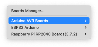
I installed the libraries via the Board manager found in the tools drop down in the arduino IDE. We then had some errors as we were not connected to the right board.

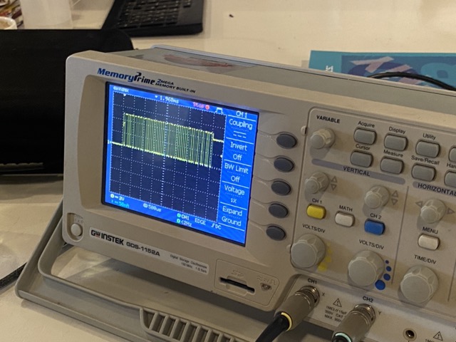
We then search for some example code on Github, connected the board and uploaded the program. We were able to measure the changes in temperature and humidity and also look for the signal sending the back the date every 2 seconds.
Hall affect sensor
We then connected a 503 linear hall effect sensor to test an analog input. Hall effect sensors measure magnetic fields that cross at a perpendicular to the surface of the sensor.
| Pinout | board | |
|---|---|---|
| 1 | Signal | A2 |
| 2 | Vcc | A1 |
| 3 | GND | A0 |
With a small magnet on the end of a screwdriver we were able to see the results:
Arduino millis:
Leo helped me understand how we can read multiple input by using millis instead of Delays. A delay is a NOP command which will tell the micro-controller to do nothing, not good if you need to read different inputs at the same time. Instead we use code that will continue to loop without a delay, by using time passed. Below is an example code.
const unsigned long intervalSensor1 = 1000;
const unsigned long intervalSensor2 = 2000;
unsigned long previousTimeSensor1 = 0;
unsigned long previousTimeSensor2 = 0;

void setup() {
  Serial.begin(9600);
}

void loop() {

  /* Updates frequently */
  unsigned long currentTime = millis();

  /* This is the event for sensor 1*/
  if (currentTime - previousTimeSensor1 >= intervalSensor1) {
    /* Event code */
    Serial.println("reading the sensor 1....");

   /* Update the timing for the next time around */
    previousTimeSensor1 = currentTime;
  }

  /* This is the event for sensor 2*/
  if (currentTime - previousTimeSensor2 >= intervalSensor2) {
    /* Event code */
    Serial.println("reading the sensor 2....");

   /* Update the timing for the next time around */
    previousTimeSensor2 = currentTime;
  }
}
Individual assignment:
- Measure something: add a sensor to a micro-controller board that you have designed and read it.
Personal Goals
- Create a new board, fix previous issues with pull down resistor [x]
- Test humidifier input [x]
- Create a test environment, Acrylic container or plastic box of some description [x]
- Use the atomizer module [x]
- Use a fan over water technique []
- Compare results []
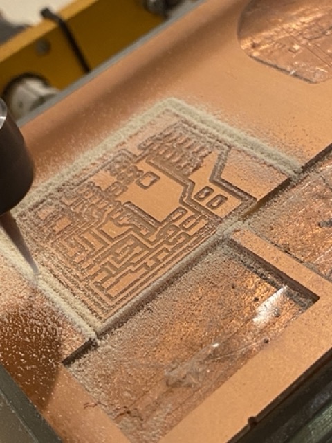
Making a new PCB
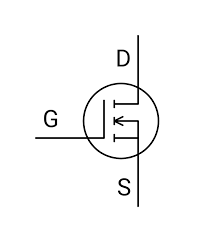
So i decided to make a new pcb to solve the issues of the past and to add some additional features. I wanted to use mosfet's to control output devices that need a 5V supply. I am using a Xiao Esp32-c3.

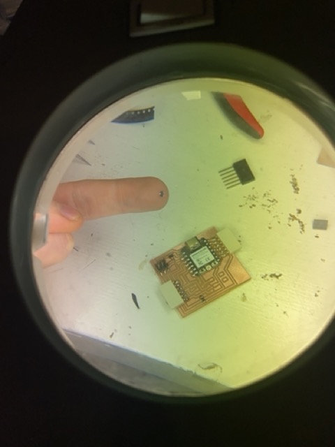
Soldering for me is quite difficult, I have big cumbersome hands, so trying to solder mosfet's was quite fun.
Testing new PCB
LED ON/OFF
#define LED1 D6
#define BTN D5


bool ledState = LOW; // HIGH, true and 1 mean the same
bool btnState = HIGH; // button is high as it is connected to 3.3V via a pull-up resistor

void setup() {
  pinMode(LED1, OUTPUT);

  pinMode(BTN, INPUT);

  // set initial state of our LED
  digitalWrite(LED1, ledState);


}

void loop() {
  bool btnReading = digitalRead(BTN);

  // we want to do something only if the reading and the state are different
  // in this case they are the same and we exit the loop immediately
  if(btnReading == btnState){
    return;
  }

  if(btnReading == LOW){ // LOW means button is pressed on Tarantino
    btnState = LOW;
    ledState = !ledState; // Flip led state by using negation operator
  }else{
    btnState = HIGH;
  }

  digitalWrite(LED1, ledState);
  delay(10);
}
New pcb and button working great, but I have made a fatal error, the design for the pcb had through hole tracks and not surface mount, so I had to solder directly onto the board, not idea.
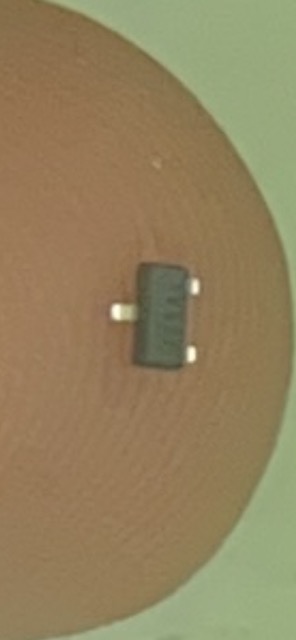
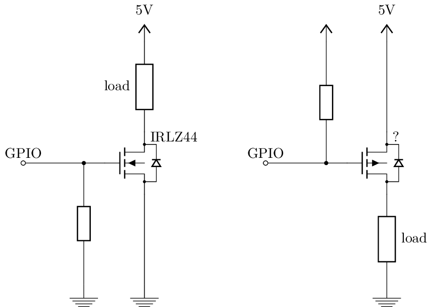
Mosfet Issues
So for every problem I fix, another arises... Or maybe I need more time with ye'th ol data sheet. My new installed mosfets do not have resistors, so spurious eddy currants and static charges can muddle any signalling I want to use them for. Below to the left is I how I wired them, compared to on the right with resistors.
Input Device
For my input I chose the DHT22, again single wire data transfer on with an 8-bit chip sending the data down pin 2.
| Pinout | Board |
|---|---|
| 1 | 5v (4.7komh resistor between vcc and signal) |
| 2 | D7 |
| 3 | Nc(relay) |
| 4 | GND |
To do more than just test the input and to help me with my final project, I wanted to simulate a humidity controlled unit, for this I needed humidity.
Testing
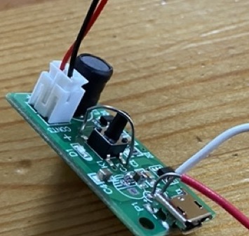
Atomizer
I found it hard to find the relevant data sheet for this module, which made things difficult in testing it as an output. Just by giving it power didn't work, because theres a button that controls two operating modes. So I made a bypass out of a thin piece of solder to test and that did the trick.
module
| Pinout | |
|---|---|
| Jumper wire | Button |
| "+" | Com relay |
| "-" | GND |
Relay
| Pinout | |
|---|---|
| 5V | NC |
| "+" | 3V |
| "-" | GND |
| "S" | A2 |
First I tested each device individually, there were some issues with assigning the correct board pin, with an output set to pin 6 it worked, when in reality I was using D3 or pin 3. Still not sure why that happened.
/* This code works with Grove Water Atomization module
 * It activate   the atomizer for 3 seconds and turn it off with a message shown of the statut
   * Refer to http://Surtrtech.com for more details
 */

#define Atomizer A2

//Atomizer EN pin

void setup() {

  Serial.begin(9600);
   pinMode(Atomizer, OUTPUT);

}

void loop() {

Serial.println("Atomization   !!!!");
digitalWrite(Atomizer,HIGH);
delay(3000);

Serial.println("Atomization   OFF");
digitalWrite(Atomizer,LOW);
delay(3000);

}
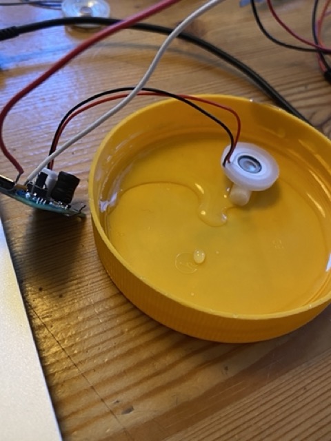
How I set up the atomizer for testing.
Atomizer with humidity control
Now I could test the two devices together, I used code to turn ON Atomizer below 70% and OFF Atomizer greater than 70%. Here are the results.
Below 70% Atomizer ON
Above 70% Atomizer OFF
CODE
#include "DHT.h" // Required libraries for DHT

#define Atomizer A2 // Atomizer EN pin
#define DHTpin D7   // DHT signal pin
#define DHTTYPE DHT22 // DHT sensor type, you can use DHT22, etc.
//#define SCREEN_WIDTH 128 // OLED display width, in pixels
//#define SCREEN_HEIGHT 32 // OLED display height, in pixels

DHT dht(DHTpin, DHTTYPE);

void setup() {
    Serial.begin(9600);
    dht.begin();
    pinMode(D6, OUTPUT);
    pinMode(Atomizer, OUTPUT);
}

void loop() {
    digitalWrite(D0, LOW);
    float h = dht.readHumidity();
    float t = dht.readTemperature();

    Serial.print("Humidity: ");
    Serial.print(h, 1);
    Serial.print("%\t");

    Serial.print("Temperature: ");
    Serial.print(t, 1);
    Serial.println("°C");

    if (h >= 70) {
        digitalWrite(A2, LOW);
        Serial.println("Atomizer OFF");
    } else {
        digitalWrite(A2, HIGH);
        Serial.println("Atomizer ON");

    delay(1000);
    }
}
Files
Reflection
Good week for making final project progress, but obviously never a smooth ride. Learned a lot and have a better understanding of how I can use mosfet's, so looking forward to trying that. I didn't get around to testing how a fan over water would work as humidifier, something to look into. Would also like to test a water detection input device.
To Do's
- Re-design board including mosfet and resistors
- Test a water detection module as input
- Test heat matt as output
- Test fan over water for humidity control
- Write code for control
Have you answered these questions?
- Linked to the group assignment page. [NO]
- Documented what you learned from interfacing an input device(s) to your microcontroller and optionally, how the physical property relates to the measured results.[X]
- Documented your design and fabrication process or linked to the board you made in a previous assignment. [X]
- Explained the programming process(es) you used.[X]
- Explained any problems you encountered and how you fixed them.[X]
- Included original design files and source code.[X]
- Included a ‘hero shot’ of your board.[X]