9. Output Devices
Group assignment:
For our group assignment we worked on various output devices and noted their power consumption, I have made some notes, but Leo kindly documented our work, you can find the documentation on his page here
- Measure the power consumption of an output device.
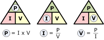
To do this we need to know what the power (watts) our device operates at. We do this using Watt's law.
Watts (P) = Voltage (V) × Current (I)
For example, if you have a circuit with a voltage of 12 volts (V) and a current of 2 amps (A): Watts = 12 V × 2 A = 24 watts
But watt about time?
Power consumption over time is measured in watts (W), which is equivalent to joules per second (J/s). This means that if a device has a power rating of 1 watt, it consumes 1 joule of energy every second.
The relationship between power, energy and time can be expressed by the equation P = E/t, where P is power, E is energy and t is time.
For most applications we work on the basis of watt hours (Wh), we can work out the energy consumption over a period of time using the following formula:
Energy Consumption (in watt-hours, Wh) = Power Rating (in watts, W) × Time (in hours)
For example, if you have a monitor with a power rating of 50 watts and you use it for 5 hours:
Energy Consumption = 50 W × 5 hours = 250 Wh
DC Motor
For out group assignment we tested two types of motor, the first was a small gearbox DC motor that Vera brought with her to class.
Using table top power supply units, we were able to supply the correct 5 volts needed for the motor to run. We set the Amps to 1, knowing that the motor(load) will only draw the amount of current(A) it requires to run.
When set to 5V it draws 43mA which means 0,22mW.
Stepper Motor
We then tried a stepper motor 17hs19-2004S1 using a drv8825 stepstick and Vera's beautiful butterfly xioa esp32.
We used this website for guidance in wiring the motor and setup.
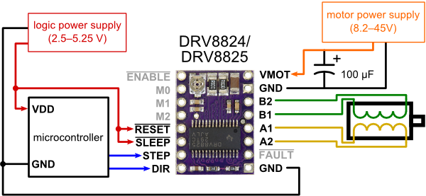
We then wrote some code to get it to move, you can find that on Vera's documentation page.
We had some issues with the motor, it was making a lot of sound when apparently it should have been smoother. We investigated and found a current limiter that controls the Vref. The pot on the drv8825 needed to be turned to set the correct amount of voltage/current to the motor. With the Vrf set to 0.5V, 1A we measured the power consumption of the steppermotor: 2.88W.
Once we had that done, we went about micro stepping the motor. Stepper motors typically have a step size specification (e.g. 1.8° or 200 steps per revolution), which applies to full steps. A micro-stepping driver such as the DRV8825 allows higher resolutions by allowing intermediate step locations, which are achieved by energizing the coils with intermediate current levels. For instance, driving a motor in quarter-step mode will give the 200-step-per-revolution motor 800 microsteps per revolution by using four different current levels.

With some new code we were able to successfully achieve micro stepping.
For my final project I will need a humidifier, so this was a good opportunity to test the power consumption of an atomizer module I have sourced vs one from the waag.
First the waag humidifier. Running at 5V we measure 0.26 Amps, so 1.3watts
Then the atomizer module. Running at 5V we measured 0.47 Amps, so 2.35watts almost double. This is way more than a USB cable can handle, so I will need to think about a power supply for my final project.
Individual assignment:
- Add an output device to a microcontroller board you've designed and program it to do something.
So from the previous weeks assignment, I new there were some improvements I needed to make to get my board to work without shorting when pressing the button. I knew the configuration of the button was incorrect, but the board was also too big and I had removed the important I2C IO's. So I went back to KiCad to improve the look and functionality of the board.

Improvements
- Increased track width to 0.6mm
- Additional connected for I2C
- Decreased layout size
- Removed 0 ohm resistor
- Rounded corners
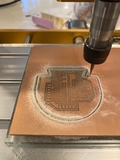
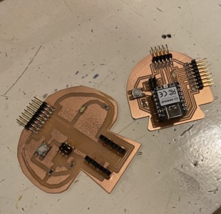
As always, the milling process wasn't so straight forward, the trusty Modela didn't seem to be doing what Mods was asking of it, I think this was due to my mac book. I then moved to the 3018 and managed to produce a good mill.
Mushroom 2.0

I then connected a small MG90S servo motor according to the data sheet, you can find there here.

- 5 volts Red
- GND Brown
- Pin28 Orange
Using the arduino libraries I used some code to get the servo motor to sweep.
#include <Servo.h>

Servo myservo;  // create servo object to control a servo
// twelve servo objects can be created on most boards


void setup() {
  myservo.attach(28);  // attaches the servo on GIO28 to the servo object
}

void loop() {
  int pos;

  for (pos = 0; pos <= 180; pos += 1) { // goes from 0 degrees to 180 degrees
    // in steps of 1 degree
    myservo.write(pos);              // tell servo to go to position in variable 'pos'
    delay(15);                       // waits 15ms for the servo to reach the position
  }
  for (pos = 180; pos >= 0; pos -= 1) { // goes from 180 degrees to 0 degrees
    myservo.write(pos);              // tell servo to go to position in variable 'pos'
    delay(15);                       // waits 15ms for the servo to reach the position
  }
}
Then playing with the delay to increase speed.
At that point I remembered I should have a working button as an input and maybe i could use that to start the motor, but then I discovered that the same issue resides in mushroom 2.0.
Debugging 2.0
I knew about internal pull up resistors due to research and Vera's did some documentation about it on her page, but I thought they were only enabled in the logic. It seems like D7 Pull up resistor can only be Enabled and never disabled on my board. From my understanding and from the schematic, we have A7 connected to a resistor and then GND, giving the LOW(OV) logic to the controller. When we push the button, we close the circuit sending 3.3V to A7 meaning INPUT logic HIGH(btn pressed).
Enable pull up resistor.
pinMode(BTN, INPUT_PULLUP);
I have now take out the physical resistor on the circuit and programmed the internal pull up resistor. This makes the button useless, because internally the board receives 3.3v for HIGH and when I press the button, I am giving another leg of 3.3v, so no state change.
Now I have reverted back to
pinMode(BTN, INPUT);
So the internal pull-up resistor disabled and the resistor removed. Now I have the function ok, but only if I'm touching some of the pins.
Truth is, I'm not 100% sure why this is happening. It looks like the board has grounding issues and the removal of the resistor, but the original schematic and design layout should work. I will try another board when I am at Waag to rule out the change it is the Micro-controller.
I found this site useful for explaining a bit more of the XIAO board IO's, but no solution just yet...
Learning outcomes
- Demonstrate workflows used in controlling an output device(s) with MCU board you have designed.
Have you answered these questions?
te - Linked to the group assignment page. - Documented how you determined power consumption of an output device with your group. - Documented what you learned from interfacing output device(s) to microcontroller and controlling the device(s). - Linked to the board you made in a previous assignment or documented your design and fabrication process if you made a new board. - Explained the programming process/es you used. - Explained any problems you encountered and how you fixed them. - Included original source code and any new design files. - Included a ‘hero shot’ of your board.