4. Electronics production
Learning outcomes
- Described the process of tool-path generation, milling, stuffing, de-bugging and programming
- Demonstrate correct workflows and identify areas for improvement if required
In Waag there are two CNC milling machines for building PCB's:
Roland Modela MDX20
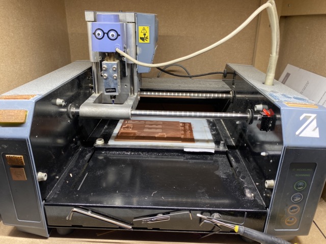
The Roland Modela MDX-20 is a three-axis desktop milling machine. Its X-axis moves horizontally across two bars, carrying the milling tool. The Z-axis controls vertical movement, extending and retracting the milling bit. The Y-axis serves as the machine bed, offering stability with multiple layers for securing workpieces. This compact machine is ideal for small-scale prototyping and modeling although it's downfall is that quite expensive to buy and it is no longer in production, so spare parts could become an issue.
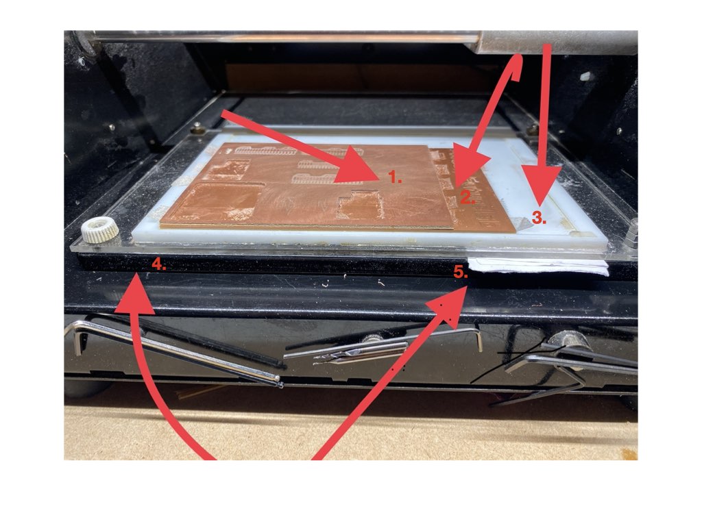
- Top layer - Your pcb material, we use F1 in our lab, made from pressed paper and copper. The F number is the fire rating and refers to it being the most flammable, but it is preferred to F4, a fiberglass board that will generate small glass particle that are a health hazard for your skin and lungs.
- sacrificial layer - To protect the level plate, we have a sacrificial layer that is essentially another scrap F1 sheet that we will leave marks on if we drill too deep.
- Level Board - This is the white layer of plastic that has been machine levelled, we want to protect this at all costs.
- Machine bed - This is the part of the machine moves on the Y axis with the other layers fastened to it.
- And last but by no means least, we have our paper calibrating shim for the ultimate imperial level.
There is also a layer of double sided tape that hold our board in place against the sacrificial board.
It is important not to overlap your tape as to maintain the same level across the board.
Operation
To operate this imperialist, we run Mods program from the a chrome based browser on the lab pc:
- Load your png file
- Set your bit parameters. (tool diameter,cut depth, max depth, offset, offset stepover)
- Mods has two editable boxes for milling bits parameters, they are end mill and V bit. We use the V bit editor for tapered bits.
- I found editing in the "mill raster 2d" box preferable as to save imperial conflict.
- Hit calculate and you should now be able to view the cut path.
Offset: The amount of times the machine goes around the pcb and therefore how many trace lines of milling the machine will do. offset stepover: is the amount the bit moves to mill the next line, this is determined by the bit size. A 0.4mm bit with an offset of 0.5 will move 0.2mm to mill the next line.

Setting up the tool
- Loosen the grub screws and fit the bit you will use, then re-tighten. (you should only have around 15mm of the bit showing from the collet)
- Hit view to move to the X/Y origin point.
- Edit the origin in mods, once you are at the correct point make sure to note the co-ordinates in mods incase you may need them later on.
- You should be above your origin point with a gap between the bit and your material, we now want to close that gap to set the Z 0 point.
- Again loosen the grubs crews and guide the bit to the surface of the material. Re-tighten grub screws.
- Now you're ready to send the file.
Pre-checks
- You're happy with the new origin point.
- You have checked the parameters are correct and pressed calculate.
- You have checked the G-code image and the right amount of line appear, the cut path is correct and you have an insulated cut path.
- You are connected to the Modela.
The Modela connects via usb port and we must pair the device before sending files. To pair select "Get Device" and then select the Modela via usb-serial controller D (ttyUSB0)*
If you have check all of the above then you're good to send the file and the machine should start the milling process.
For the results of the group assignment on the Modela, please refer to Leo's page using this link.
Lunyee 3018 milling machine
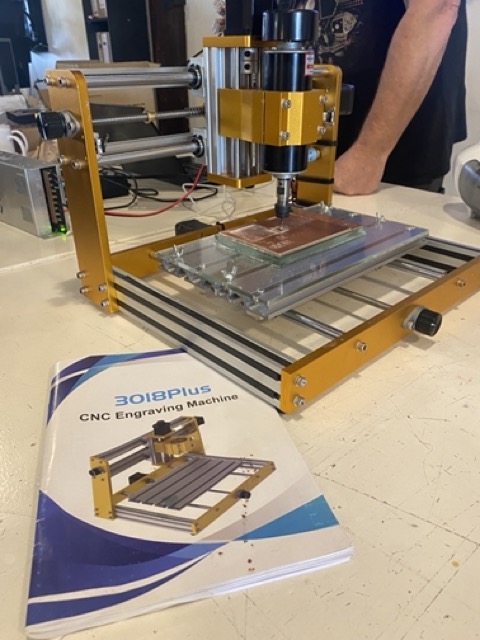
The budget 3018 works in a similar fashion to the Modela, working from 3 axis as shown below.

The difference lies in the operating system. We use UGS To send a G-code images to the machine, to do that we must first generate a G-code using Mods.
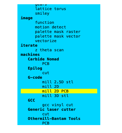
User guide
- Enter cut parameters in mods.
- Hit calculate, this will then download the G-code in your browser.
- Select the download and open it with a text editor, in my case I used Visual Studio code.
- You should then have a mark down file full of code, Select all and copy.
- Then open UGS
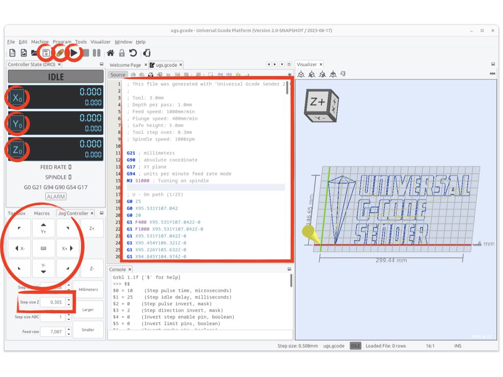
UGS
- First we need to clear any data in the G-code file.
- Then paste the new G-code we just generated from mods that should now be in a markdown file.
- We will need to connect to the machine from the tool bar.
- Save the file.
- Before pressing Play, we need to used the arrows to toggle to our start point and set our origin.
- When we have our X and Y we can zero them in the Idle menu.
- For the Z axis we use a paper gauge to set the Z origin:
- Move down to within a couple of millimeters from the board and then set the 'Z step size' to 0.1
- incrementally move down until the paper becomes fixed.
- move up 0.1 and remove the paper.
- Move down 0.1 Then Zero your Z axis in the idle menu
- You can now hit play.
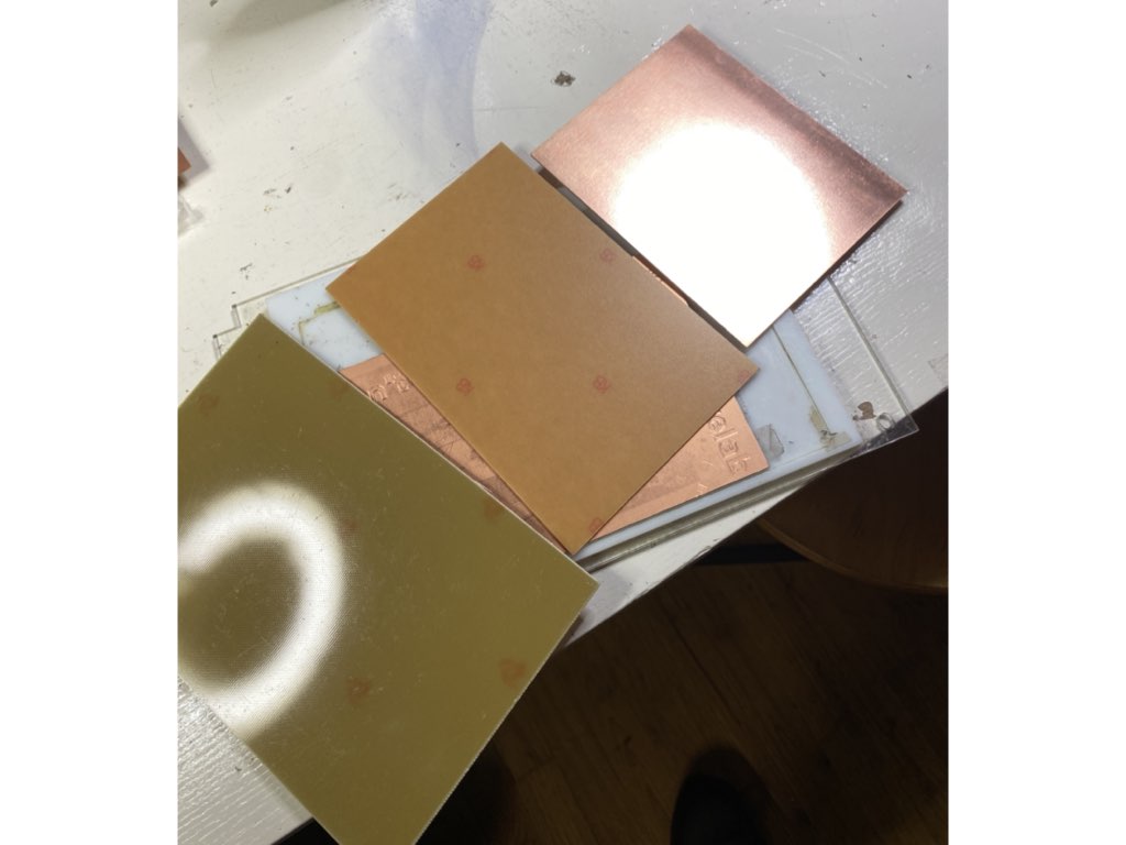
Material
From left to right we have F4 Fiberglass, F1 and F1 double sided:
Milling Bits

From left to right we have the V-bit, end mills 0.8, end mill 0.4 Four, and the tapered bit. We will test each of these Bits in our assignment to determine which one performs the best.
Group assignment:
For the group assignment our class split into two groups and I teamed up with Leo Kuipers, please follow the link to his documentation page.
Line Test
The table below shows our parameters for the line test using different milling bits. For the first V bit test we accidentally made a mistake and left the cut parameters the same as the Tapered bit, this meant we cut deeper than expected. The lines actually turned out quiet nice though, maybe the best from the test group. I would suggest the tip of the tool is slightly blunt and so leaves burrs, whereas when cutting deeper the sides of the tool are sharper and therefore produce a better finish.
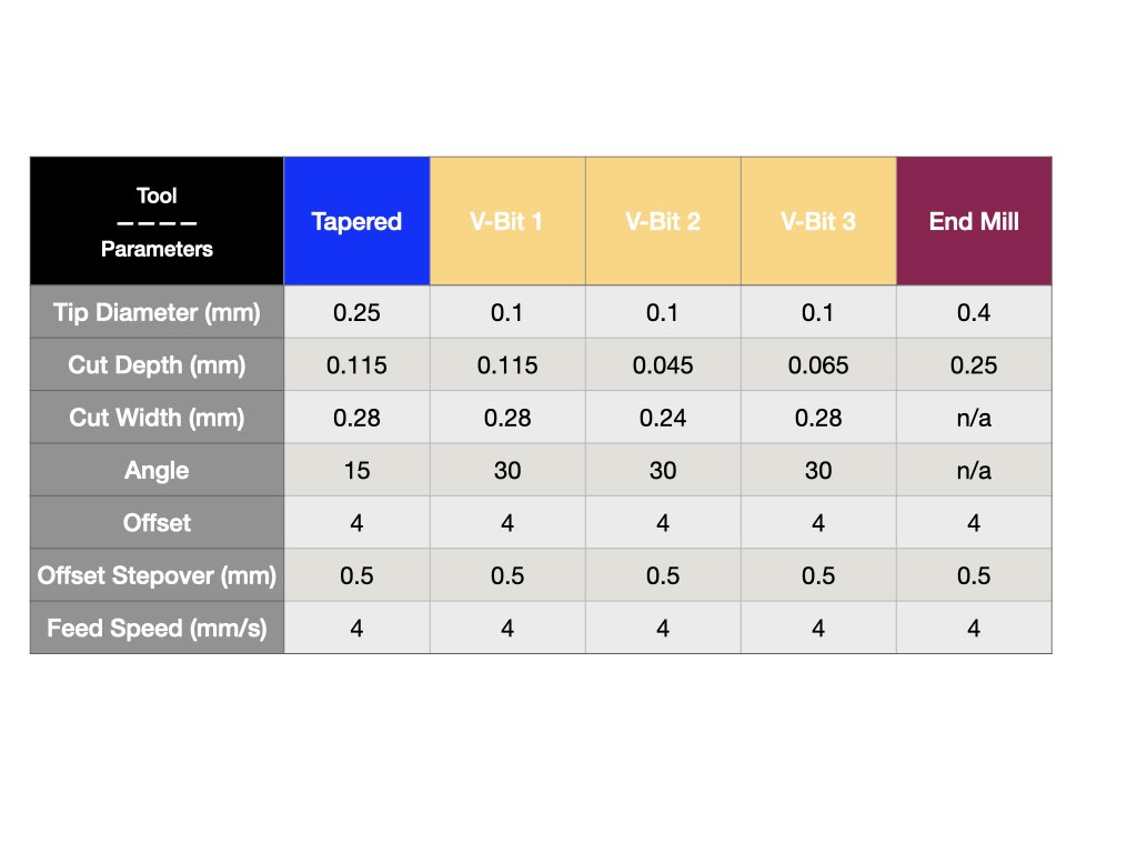
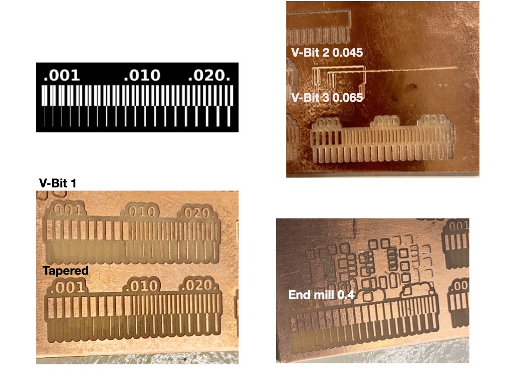
From our findings I would suggest that with the correct parameters, the end mill works best followed closely by the tapered bit. The V-bit was hard to set up and left too many burrs, but I would like to test a brand new V-bit out of the box to see if a sharper tool performs better.
Individual assignment:
- Make and test a micro-controller development board.
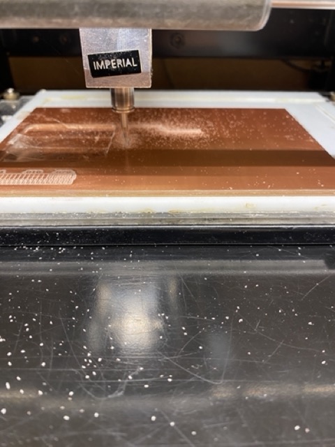
Following the steps from Quen Torres tutorials, I used the design png files to go about making my micro controller. For this I used the Roland Modela with a 0.4 end mill for the trace lines and a 0.8 end mill for the drill holes and the cut out.
After setting the parameters I started with the traces line.
I then changed the bit to 0.8 and entered the drill png, here I made a mistake... I didn't calculate, so when the tool started it went back to the trace lines, only this time with a bigger bit, which ruined my first board.
So, back to setting the milling parameters for a second go...

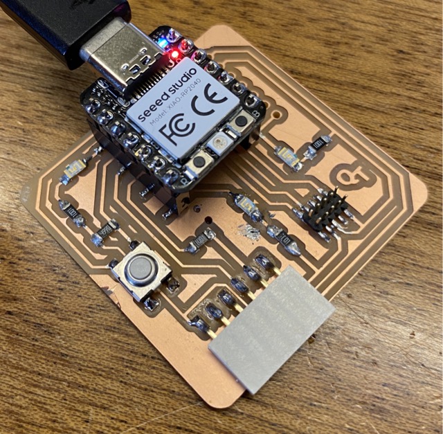
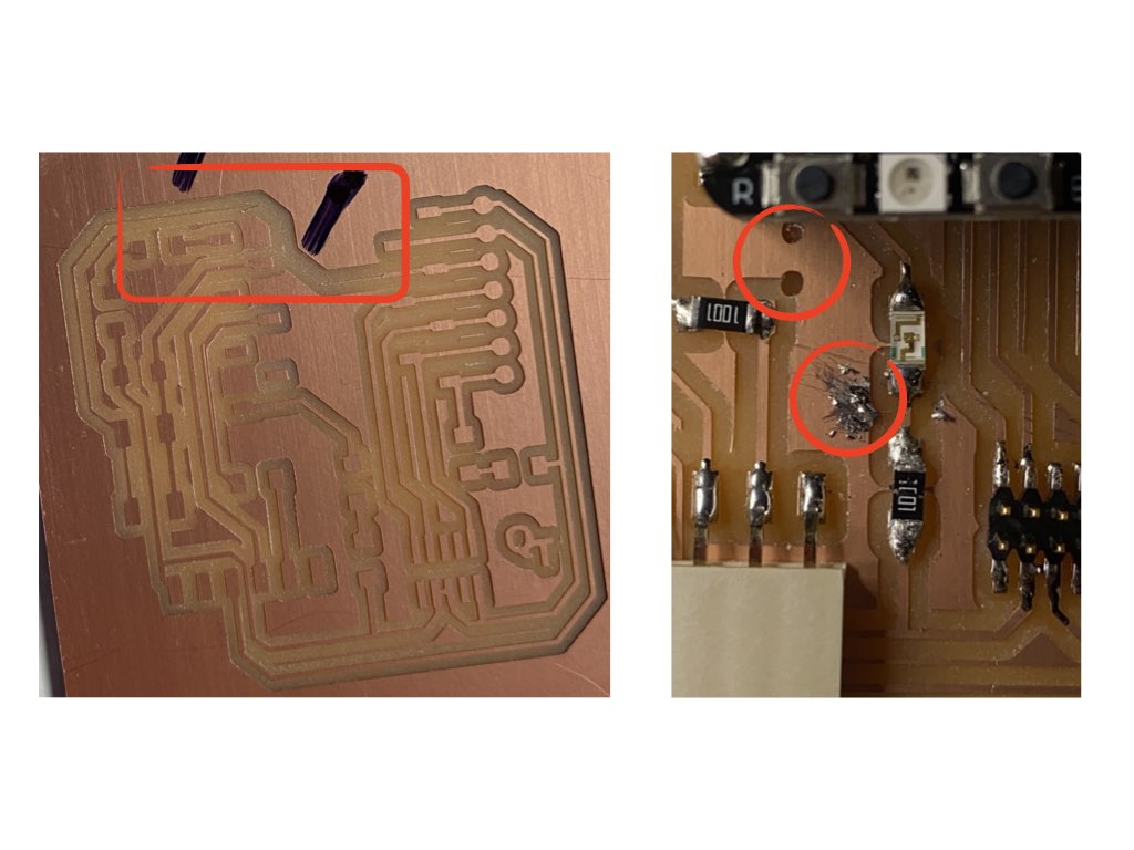
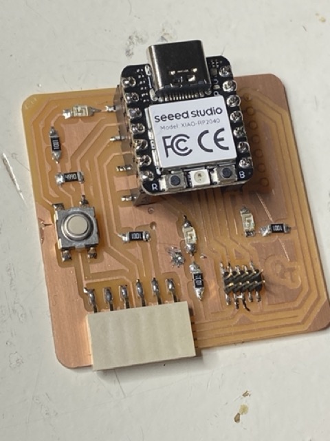
I could then drill the holes and cut it out before staring to install components. An important test with the multi meter lets us know the orientation.

I made a bit of a mess soldering but it's not connected to the circuit so won't affect how it runs. You will also notice two holes in the board, this was due to the drill png image still being sent to the roland we had to reset the machine. This also reset the co-ordinates for the drill holes, luckily they did'nt cut through any lines and we could use some clever guess work to set the origin.
Here she is...
Once I had all the components soldered I then followed the documentation on how to program it and see if i could get it to blink.
Firstly by downloading the Arduino IDE on my mac, you can get that from there website here .
After resetting and loading new code I was able to blink the LED and then change the blink rate, I was also able to switch the LED On/Off using the button. Please see video and code below.
Blink code - This is with parameters set to 50ms, so rapid blinking.
/*
  Blink

  Turns an LED on for one second, then off for one second, repeatedly.

  Most Arduinos have an on-board LED you can control. On the UNO, MEGA and ZERO
  it is attached to digital pin 13, on MKR1000 on pin 6. LED_BUILTIN is set to
  the correct LED pin independent of which board is used.
  If you want to know what pin the on-board LED is connected to on your Arduino
  model, check the Technical Specs of your board at:
  https://www.arduino.cc/en/Main/Products

  modified 8 May 2014
  by Scott Fitzgerald
  modified 2 Sep 2016
  by Arturo Guadalupi
  modified 8 Sep 2016
  by Colby Newman

  This example code is in the public domain.

  https://www.arduino.cc/en/Tutorial/BuiltInExamples/Blink
*/

// the setup function runs once when you press reset or power the board
void setup() {
  // initialize digital pin LED_BUILTIN as an output.
  pinMode(D0, OUTPUT);
}

// the loop function runs over and over again forever
void loop() {
  digitalWrite(D0, HIGH);   // turn the LED on (HIGH is the voltage level)
  delay(50);                       // wait for a second
  digitalWrite(D0, LOW);    // turn the LED off by making the voltage LOW
  delay(50);                       // wait for a second
}
Code for switching LED ON/OFF:
#define LED D0
#define BTN D1

bool ledState = HIGH; // HIGH, true and 1 mean the same
bool btnState = HIGH; // button is high as it is connected to 3.3V via a pull-up resistor

void setup() {
  pinMode(LED, OUTPUT);
  pinMode(BTN, INPUT);

  // set initial state of our LED
  digitalWrite(LED, ledState);
}

void loop() {
  bool btnReading = digitalRead(BTN);

  // we want to do something only if the reading and the state are different
  // in this case they are the same and we exit the loop immediatly
  if(btnReading == btnState){
    return;
  }

  if(btnReading == LOW){ // LOW means button is pressed on Tarantino
    btnState = LOW;
    ledState = !ledState; // Flip led state by using negation operator
  }else{
    btnState = HIGH;
  }

  digitalWrite(LED, ledState);
  delay(10);
}
Reflection
It's been a fun week, i've enjoyed the process of building the circuit boards, I also felt a real collaboration in the group assignments this week. Maybe i'm just happy because there was no CAD, but I still think I learned a lot this week.
Have you answered these questions?
- [ x ] Linked to the group assignment page
- [ x ] Documented how you made the toolpath
- [ x ] Documented how you made (milled, stuffed, soldered) the board
- [ x ] Documented that your board is functional
- [ x ] Explained any problems and how you fixed them
- [ x ] Uploaded your source code
- [ x ] Included a ‘hero shot’ of your board