3. Computer-Controlled Cutting

Group assignment:
- Characterize your laser-cutter's focus, power, speed, rate, kerf, joint clearance and types.
- Document your work to the group work page and reflect on your individual page what you learned.
Laser cutter
Brm 90130
This week we get to start playing with the machines, yay!
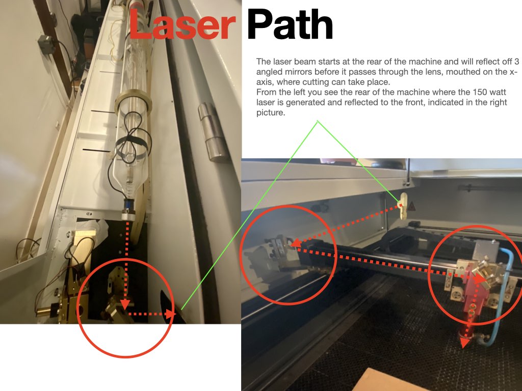
At Waag we have BRM 90130 150watt C02 Laser cutter designed for cutting metal (our machine does not cut metal as an oxygen tube is required for increasing the power of the laser), acrylic and bio materials like wood, fabrics and leather. Materials are cut on an adjustable honeycomb bed, designed so that smoke, sut and small debris can be extracted via the the holes. At Waag we have a (BOFA) fume extraction unit connected to the cutter, that will need to be turned on when using the machine.
At the back of the machine you find the glass tube containing the c02, where the laser beam is produced. Lasers produce heat and light, to counter against heat, the glass is cooled via a separate water cooler (cw-5000) thats circulates distilled water through the glass.
The machines main operating features are cutting, scoring and engraving. With cutting and scoring the laser head will follow a laser path like drawing one line from start to finish. This function is the same for scoring, but we alter the setting so that we do not cut through the material. When engraving the head will swing on the X axis like a printer head etching smaller pieces as it passes. It is important for both cutting and engraving, that a clear path is available for the head to move, if we want to keep material weighed down, we must first check for clearance.
safety features
- A laser cannot be emitted with the lid open.
- An emergency stop button, positioned at the top right side of the machine can be pressed to stop the machine.
- Compressed Air at the head pushes sut and debris through the material to prevent smoke/fire.
- Tinted glass to protect from hazardous light emission.
The laser cutter comes with its own computer and operating system, but for the functionality and improved user interface, a separate pc has been connected with a monitor running the operating system Lightburn.
Lightburn
With lightburn you can import various types of vector graphics and image formats (including AI, PDF, SVG, DXF, PLT, PNG, JPG, GIF, BMP). You can also use the software directly to draw cutting graphics. There is plenty of useful features such as auto closing open vectors, removing double vectors, boolean operations and alignment tools and text addition. We can also adjust the parameters
There are many parameters we can adjust depending on the material and function we require. Here are some of the basics i have learned so far.
Framing
Framing will allow you to see where the head will move during cutting, handy for positioning your material in the correct place. Preview icon allows you to see the image you are sending to the cutter.
group Assignment
For my group assignment I paired with Edwin please follow the link to his page.
Turning on To turn on the machine we first turn the isolator followed by the reset button. The laser head will the move on the X and Y axis until if finds it Home position.
Position On lightburn you have a green dot at the bottom left of your document to indicate the starting position, this can be adjusted on the image and in the menu, but we should try to keep this a constant and set to current unless it's absolutely required.
Setting focus There is a focus piece used to set the focus of the laser, we simply lay the piece on top of our material and adjust the nozzle height using the screws indicated below.

Part of the group assignment was to determine the focus of our machine, so we made a small wedge with lines spaced 10mm apart, the idea was to start from one side to the other and draw a line, the depth of the material will directly affect the focus and therefore the cut. With this simple test, we should be able to see and measure where our focal point is. We would expect the line diameter to change thickness until we can determine at what point of focus generates the perfect cut.
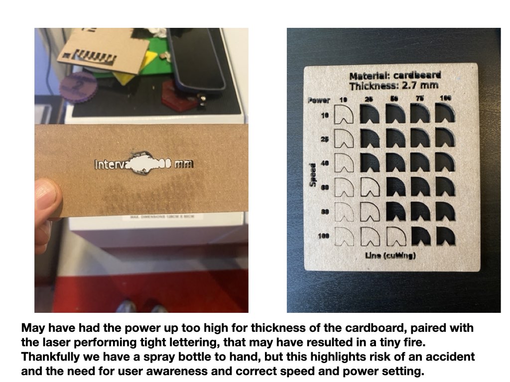
Speed and power test
For the speed and power test we can select the material and thickness and the generate a test graphic that will plot speed against power on an X and Y axis. With higher the speed you decrease the amount of time the laser is in one point so you should see a reduction in cutting. Power is equal to the amount of energy output at one point, as this increases and decreases we will see a change in cutting power. Setting are pre determined for material types and depth, but you can adjust this and make test cuts for better results. A Min and max parameter may need to be adjusted if we have black spots in corners, this is due to the slowing down and speeding up of the head, if the head slows down to corner but power is still at full then we see burn circles.
Kerf
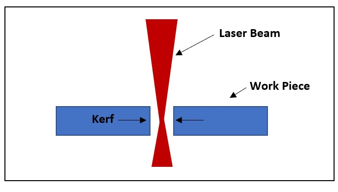
It is important to determine the amount of Kerf our machines cut so that we can factor this parameter into our drawings and produce the correct measurements in our final pieces. Kerf is the amount of material we cut away when the machine passes through our material. To measure this we designed an parametric drawing of 10mm rectangle tabs, if we place all the tabs together after cutting and measure the outcome, then we can determine the total amount of kerf loss. With that number we divide by the amount of pieces, 10, to give us the amount of kerf per line drawn.
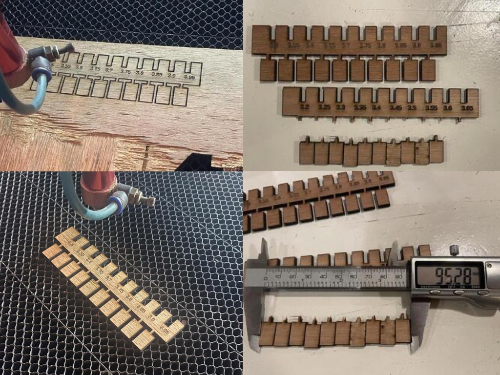
So from the measurements above we can do a calculation of the Kerf:
100 - 95.28mm = 4.72mm 4.72/10 = 0.47mm Wood Kerf = 0.47mm
For offsetting parametric drawings we would use a half kerf 0.24mm We realized that this was actually quite high and after some inspection of the machine, smudges where found on the mirrors that were affecting the focus point and heating the lens housing.
After some cleaning and refocusing we had kerf results of 0.33mm with a parametric offset of 0.16mm.
Joint clearance
With the same design we could also determine out joint clearance for the perfect press, this will help us to set the right offset parameters into our parametric sketches.

Individual assignments
- Design, laser-cut, and document a parametric construction kit, accounting for the laser-cutter kerf, which can be assembled in multiple ways.
For my individual assignment I wanted to stick to the guidelines and not think too much about what would be the final product, rather what parts could I make that could then go on to build lots of geometric shape, a kind of laser formed Lego or Meccano of sorts.
Parametric Sketch
I first started with designing a basic parametric design piece, making slots with a chamfered edges that would aid the press fit construction.

From the initial circular design I was able draw arc lines to a center point made with construction lines, from there I could mirror specified lines against construction line to then create bone shaped piece.
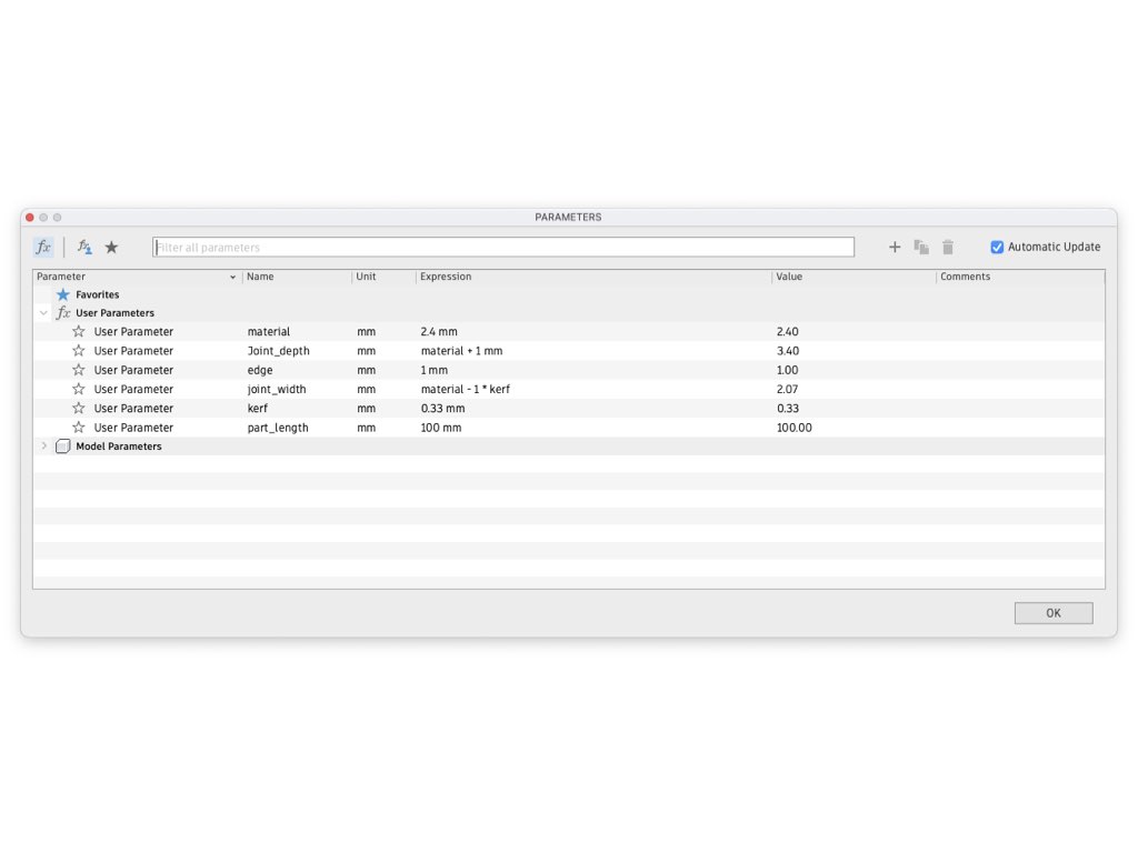
I set parameters for material, slot depth/width, length, chamfer and of course kerf so that the when exported and cut the slots should press fit. I used the same sketch to create several pieces and once I had a basic set I could exported the files. To format the sketch for the laser cutter you first have to project the sketch and then with the sketch projected you can then save the .DXF file. From here I transferred the file to USB and then you can simply plug into the laser cutter computer, open light burn and then select the file.
From there I went on to make a collection of parts that I could later start cutting and seeing what they could go on to build.
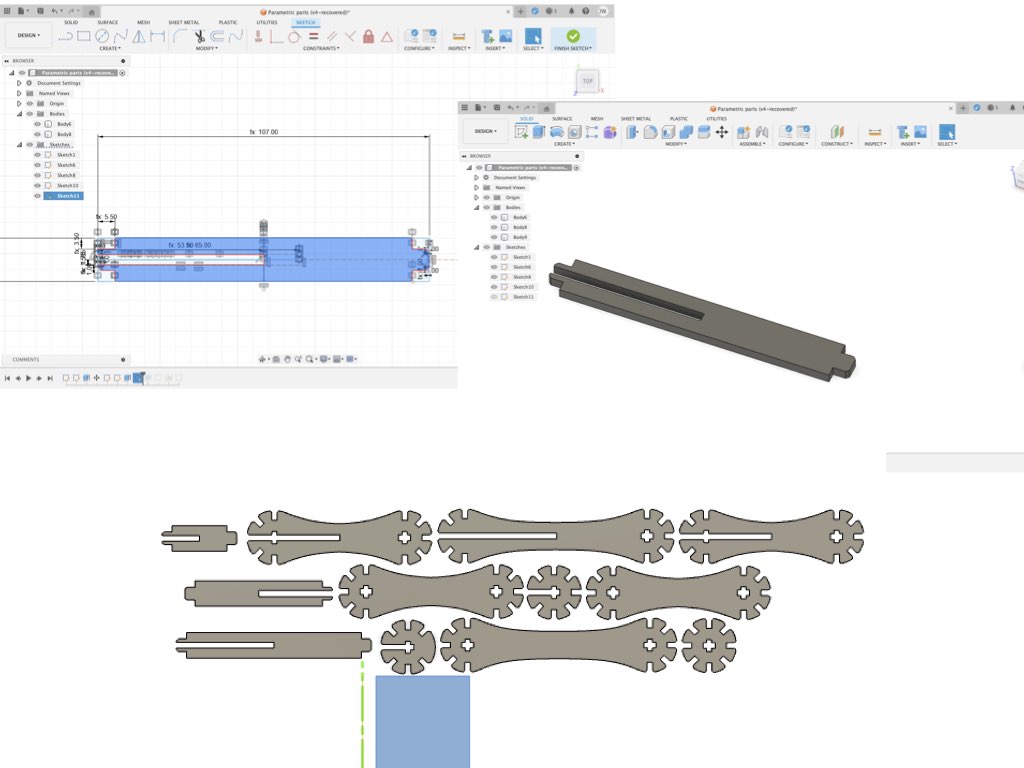
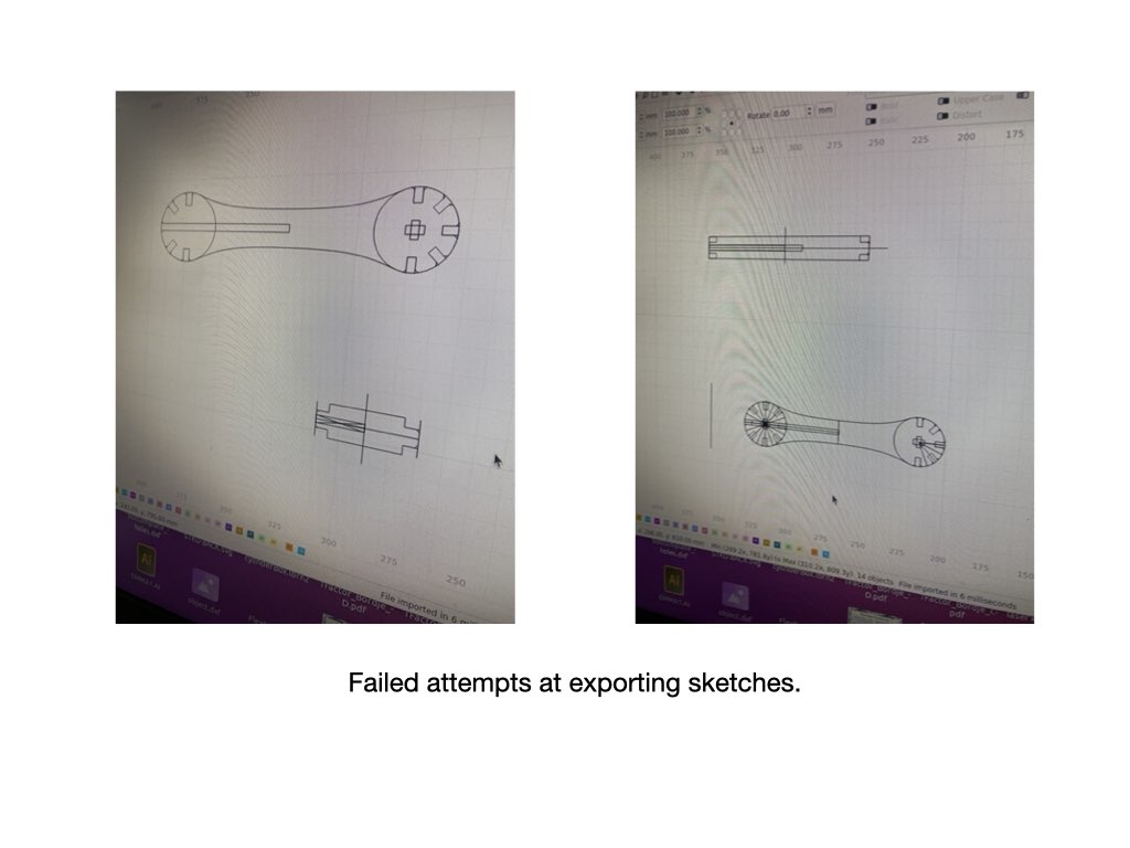
One of the most frustrating parts for me came when exporting sketches to .dxf files. To do this you need to create a new sketch from an extruded version of your design. I spent a lot of time projecting my sketches and trying to rid the lines I didn't want later using editing tools, but with the curves and other line intersections it was never going to work. With an extrusion you will get all the lines you want to keep and remove the ones you don't need.
Create new sketch -> click the 'create' drop down -> select project/include -> then select the body you want in your dxf file, this will generate a projected sketch with a purple outline and a new sketch is created in your browser bar, from there you can right click and save the sketch as a Dxf.


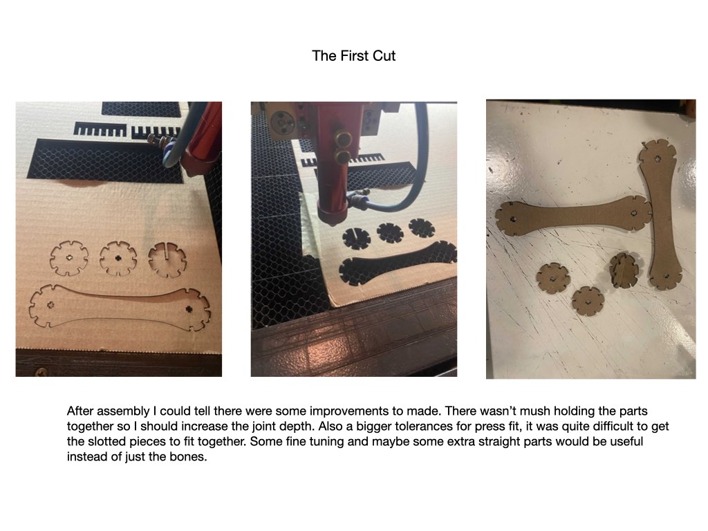
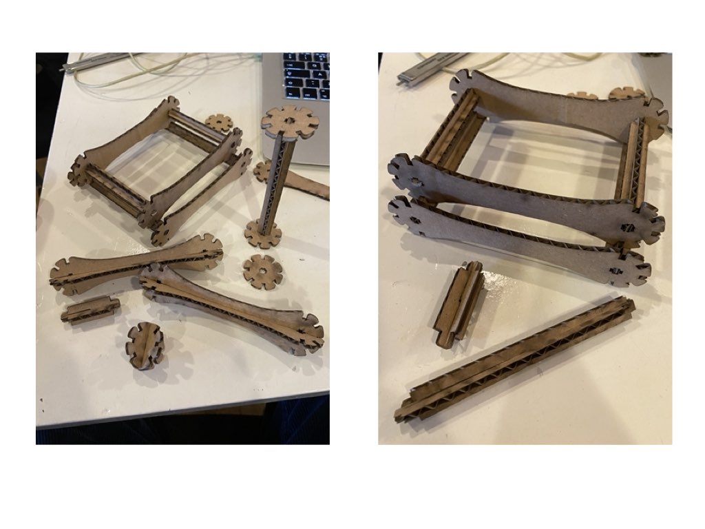
Here are some of the constructions I have made so far. It's not exactly how i would have like it to turn out, to make better geometric shapes i should have made different shaped pieces and more of them. I would have also like to try to use wood as some of the cardboard edges aren't strong enough and bend when you try to slot them into the smaller cut outs.
Frustrations
I'm at war with Fusion at the moment, I don't have the right license which has become an issue when trying to export .dxf files. With the correct license I should be able to create a 2D drawing from which I can export, but for me after many failed attempts, I found I have to create new sketches from the extruded bodies.
Vinyl Cutter
Assignment
Cut something on the vinyl cutter.
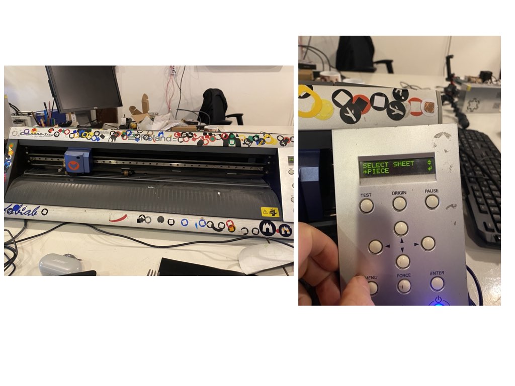
The vinyl cutter I used for this part of the assignment was the Roland GX-24 Desktop Vinyl Cutter. There are two roller on the machine that clamp down and guide your material, while the knife moves on an X axis cuts the material with a rotating knife.
The main setting we need to be concerned about are:
Origin- Where the cutting starts select sheet - set this to "piece" the cutter will then feed in your material and measure its length and width. Test - Cuts out a square within a circle, you should be able to remove this with relative ease. Force - Adjusted in mods, but tests can be made on the machine first.
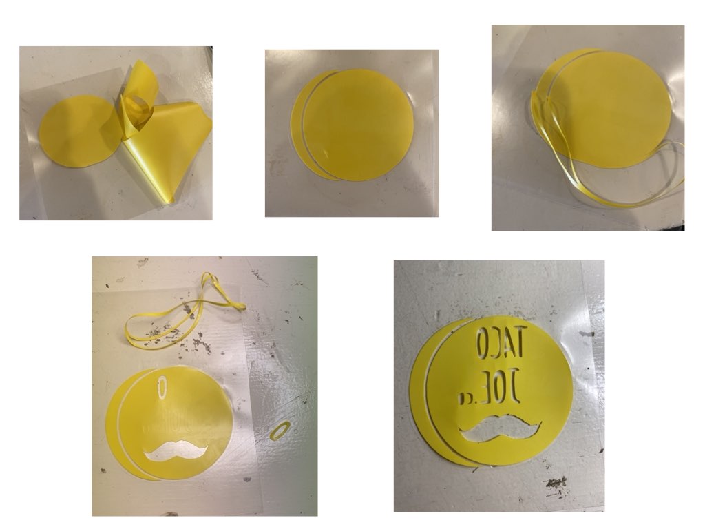
I wanted to use the vinyl cutter to make a branded t-shirt for my part time food venture. To do this I would need to edit my logo so that it is mirrored, increase the text size for weeding purposes, before sending the image to the cutter. I did this using inkscape, first I imported the .png file, made edits to text size and border thickness, grouped the parts together and then mirrored the image.
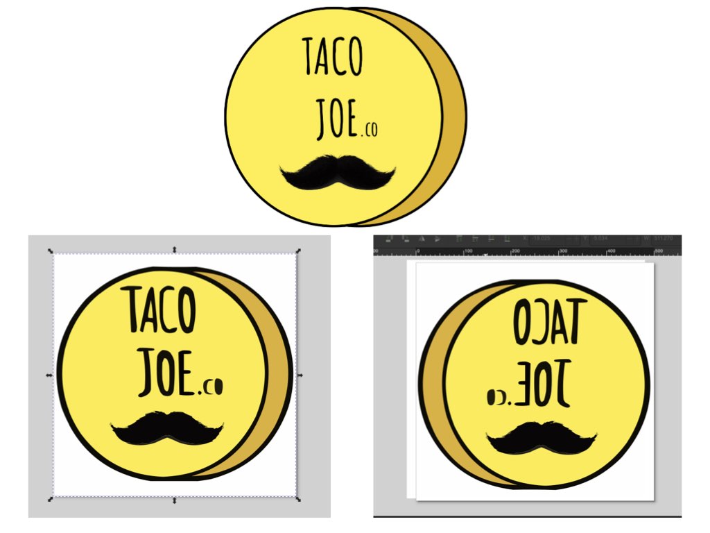
Once I had the image I wanted, I could go about sending it to the cutter.
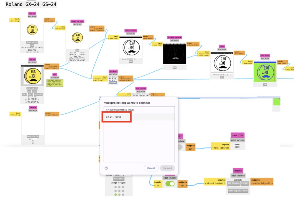
The vinyl cutter uses mods, a code based platform, only available on chrome based browsers. Mods is where you can make edits to your file and cutting parameters as well as viewing the tools cut path. If you need to make adjustments to cut force for your piece, it will have to be edited in mods, if like i did, you do a test cut on the machine itself and adjust the force on the machine, this will revert back to default when you go to send your files.
To get started open up mods in the browser.
Right click -> Programs -> select the machine - roland GX-24 -> select 'cut' (the only operation for our machine)
This will open up your interface to the machine. You can then upload your png, svg and hpgl files into the relevant box and check the parameters accordingly. I changed the image size by editing the "units" box, I set the force to 120 after a test cut. You will then need to hit calculate, check the origin is where you want it and make sure you are paired to the cutter. Then send your file and the machine should start its cut path.
Once cut, I released the clamp holding the material and went about weeding out the parts I don't need.
Now with that I was ready for my first thermal transfer, but first i had to nip to h&m and buy myself a T.
We had a quick read of the instructions for thermal transfer, set to 320 Fahrenheit for 10-15seconds was advised, but after a test peel we decided for closer to one minute.
And here are the results...

Design files
Learning outcomes
- Demonstrate and describe parametric 2D modelling processes.
- Identify and explain processes involved in using the laser cutter.
- Develop, evaluate and construct a parametric construction kit.
- Identify and explain processes involved in using the vinyl cutter.
Have you answered these questions?
Linked to the group assignment page. Explained how you created your parametric design. Documented how you made your press-fit construction kit. Documented how you made something with the vinyl cutter. Included your original design files. Included hero shots of your results.
Reflection
A lot of frustration with using fusion 360 ineffectively and not finding the solutions easily. In the end a frustration equals learning and i've definitely put some steps forward into the mountain I seem to be climbing. I also need to get more custom to file conversion and organizing my files to make it easier to locate them. Time management is also becoming quite an important, I do need to organize my week and track my progress.