7. Big build Week
To be continued...
Group assignment:
- Complete your lab's safety training
- Test runout, alignment, fixturing, speeds, feeds, materials and toolpaths for your machine
- Document your work to the group work page and reflect on your individual page what you learned
I was wondering how to start my documentation for this week, but then I remembered...

Safety Guidelines:
Wear Appropriate Attire: Always wear appropriate personal protective equipment (PPE), including safety glasses, hearing protection, and closed-toe shoes, when operating the CNC machine. Avoid loose clothing and jewelry that may get caught in moving parts. Gloves, Googles and ear plugs can be found under the work bench.
Inspect the Machine: Before each use, visually inspect the CNC machine and its surrounding. Does the xy axis have space? are there any obstructions to the side or back of the machine?
Machine Setup: Properly secure the workpiece to the machine bed using wood screws. Make sure the tool path does not collide with the screws. When an 18000rpm mill bit hits a screw, small fragments of hot metal make their way into a pit of fuel with a flowing supply of air, completing the fire triangle. Action must be taken immediately to save the beautiful Waag from burning down.


Emergency Stop: Familiarize yourself with the location and operation of the emergency stop button on the CNC machine. In case of an emergency or unexpected situation, immediately press the emergency stop button to halt machine operation. It's also good practice to hover over the space-bar when starting the cut path, this will pause the movement of the XY axis, and as I learnt, the spindle will also stop automatically.

Testing and programming: Double-check the CNC program (G-code) for accuracy and completeness before running it on the machine. Always perform a dry run or simulation to verify the toolpath and ensure that the machine behaves as expected without cutting material. You can do this by setting the Z axis to cut 20mm above your piece so that the machine frames the material, similarly to the laser cutter.
Supervision: Never leave the CNC machine unattended while it is in operation. Stay present and attentive to monitor the machining process and be prepared to intervene if necessary.
Cleaning and Maintenance: Regularly clean the CNC machine, work area, and cutting tools to remove debris and prevent buildup. We have a lovely yellow hover at Waag.
What to do when you screw
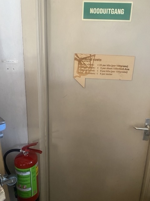
Fire Prevention Procedure
- Emergency stop - Both the CNC and importantly, extraction fan must be stopped immediately.

- Key - Stop the spindle moving and potentially sending more hot rocks to the fire.
- stop the dust collector
- Assess the situation - Check for the smell of smoke and visibly check for embers. Release the clasp and check inside the bin


- SMOKE? - If the bag is smouldering, throw the bag out of the nearest window
- FIRE? - Raise the alarm and use the foam extinguisher closest to the dustbin before evacuating the building.
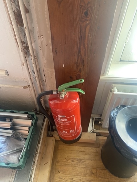
- Fire escape - There is a spiral staircase at the back of the workshop or use the main stairs at the front of the building.
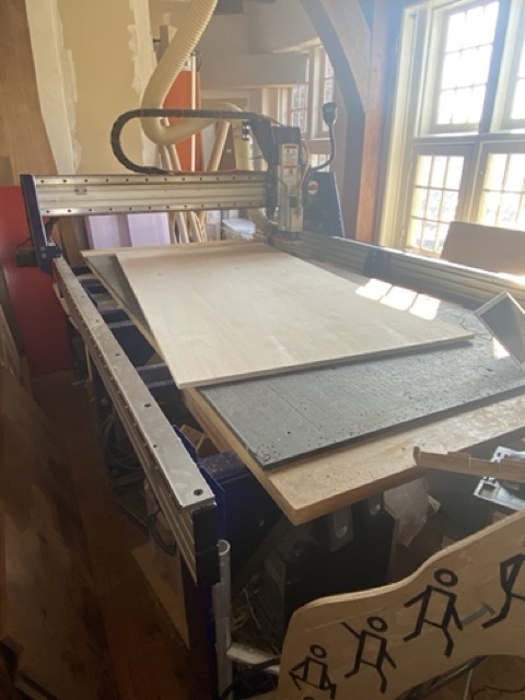
The shotbot operation
Now we know how to play safe, here are some steps to take when setting up the machine:
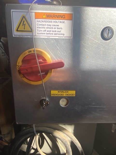
- Start the machine with the isolator
- Take the key our or check its not in the reset position
- Open shotbot 3
- Close down spindle control pop-up
Moving Axis
- visually check there is clearance to move the machine
- Press 'K' on the keyboard, arrow keypad opens
- Use arrows for xy movement
- Use 'page up' & 'page down' for Z axis
- Hold cntl for faster movement
- Space bar to pause operation

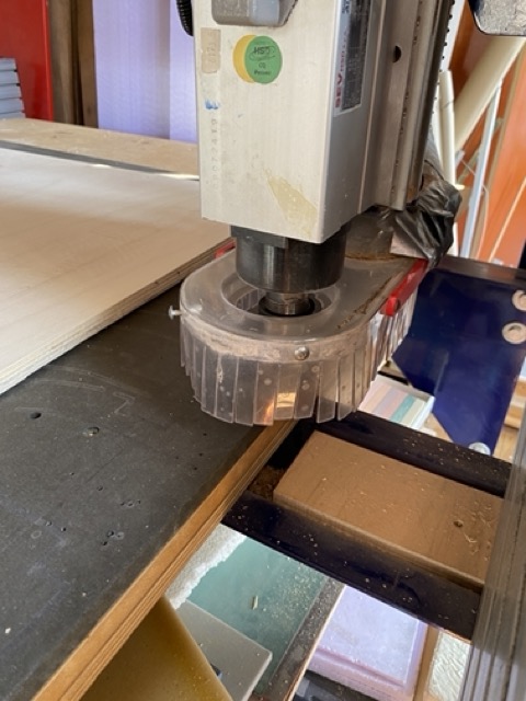
changing the mill
-
release the skirt by loosening the wing nut
-
use the two spanners to release nut
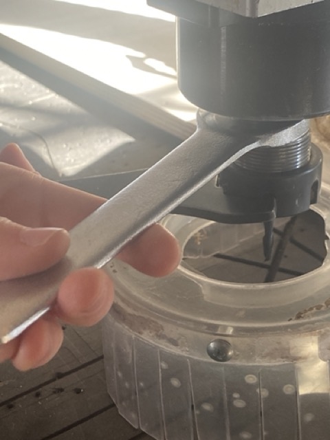 You will notice the spanner for releasing the nut has the spindle key attached for obvious safety reasons, keep it so.
 - Place the collet size you require in the nut

- Grab the correct milling and place in the collet

Only grab the soft metal on the bit an not the hardened end.
- lock back in place, make sure shes tight!
- replace the skirt, finger tightening the wingnut.
Setting zero
There are a few Zero types in the drop down for X/Y, we want to concern ourselves with zero(2).
The aim is to set the zero at our start point and not tell the machine to start at its complete zero point.
 This will create a new temporary home position for the xy axis.
Set machine XY 0
- press K for keyboard
- Jog to your start position
- Take a picture or record the numbers
- zero tab - zero |2| x & y
- Now if you press jog, machine goes to our new start point
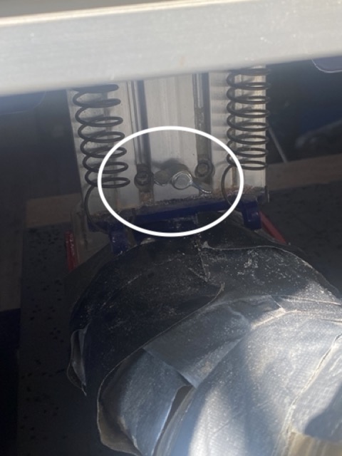
Zeroing the Z
You can zero either on the material or on the sacrificial layer. We use the sacrificial layer as this is a constant point of reference and we don't want to go any deeper than that point.
There is a metal zero plate that will give an closed loop signal to the machine on INPUT 1. We can check continuity on input 1 by tapping the metal plate against the endmill.
- PLace the metal plate on the sacrificial layer
- Press Zero Z button
- Once the mill touches the metal plate the zero is set
- Move the z up and press enter
Its good practice to check the zero, if you have a material of 18mm, move to the surface of the material using the arrows and see what reading you have before starting the shotbot.
V carve
We use V carve to make our vector file into a shotbot code, similar to a g-code
Get familiar with the orientation of the xy on the screen: - Y short side - X long side - Z set to bottom (scarificial layer)
fillet tool - edit object - create fillets
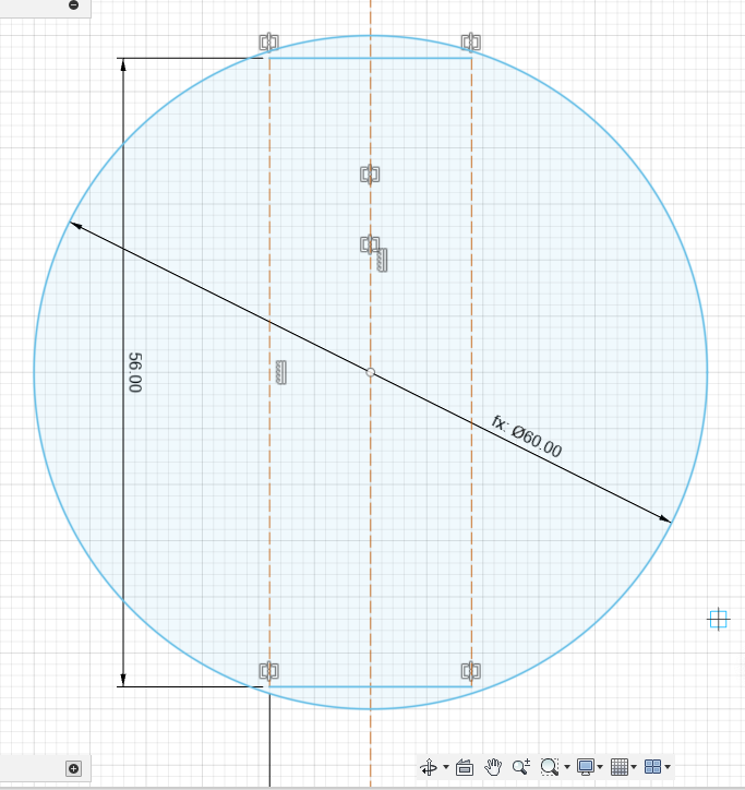
Create vectors - screw positions
The first commands we make are to set out our material and fix it in place. we do this by creating 5mm circular vectors for our screw holes fillet tool - edit object - create fillets
tool path
1. Drilling tool path, cut depth = start depth= 0 top of material
2. select tool - pick from database
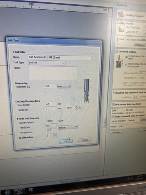
3. edit = locally edit milling bit parameters
- diameter bit
- pass depth = 2.5mm the amount of milling per pass
- step over = amount of bit that continues on next path
- spindle speed = typically set to 18000
- feed rate ms
- plunge rate ms
vector selection order - have control the tool path and order of milling preview tool path
pocket tool path
- offset
- raster
- cut direction
- climb
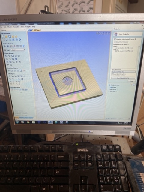
- Save tool path
- Save where the drill holes go first.
- Make sure the profile and pocket are saved as a different file
Remember - Space bar will pause the machine, but not the spindle.
Individual project:
- Make (design+mill+assemble) something big
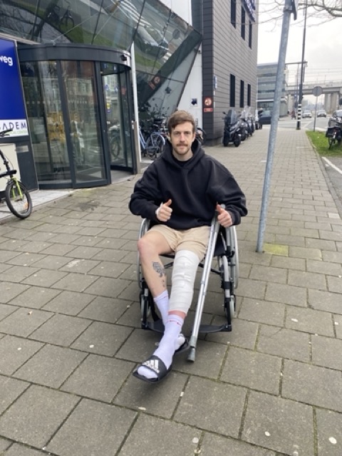
Unfortunately through illness and having an operation, I have not had time to build something big, but i have designed a big thing to build when I am able to. Here is the design process.
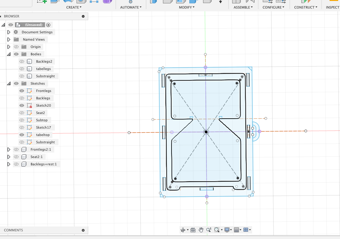
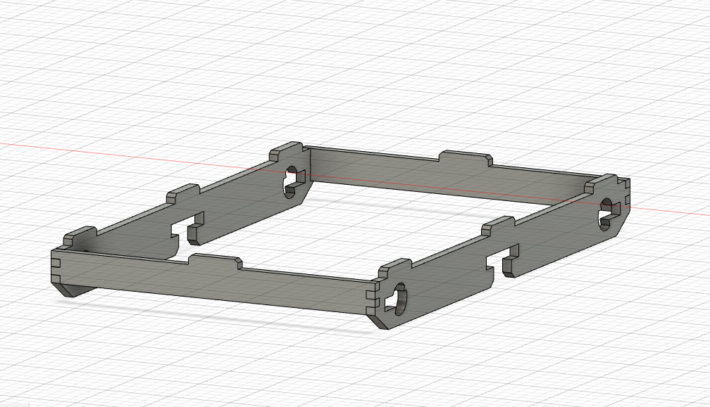
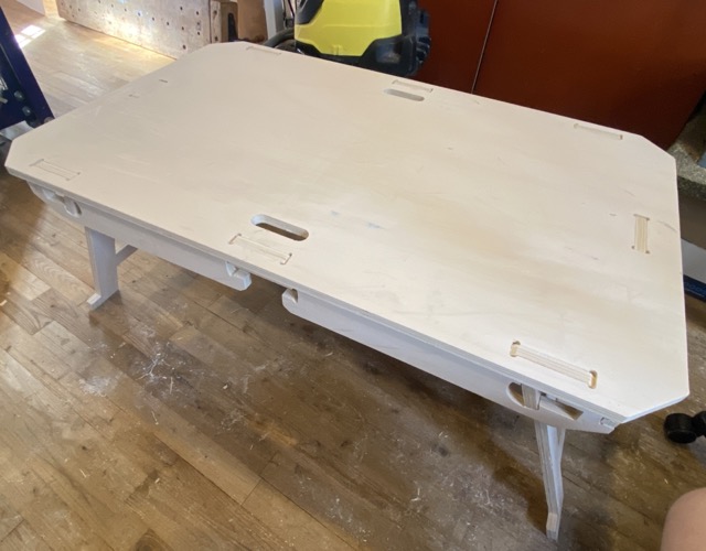
Folding camp set table and chairs
Seeing a few ideas online decided to try and replicate and improve on them. There are many example of fold out chairs online, many example too of fold out tables, but not the whole package. I have upgraded the designs on both, with adding feet to the chair and creating a lock system to hold the chairs in place

Checking clearance on the moving parts
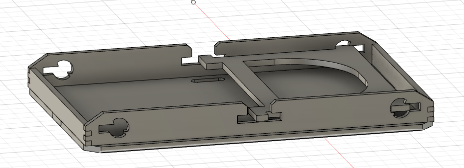
Flat pack chair design

Sub assembly - will allow the legs to fold in and then retract into a slot, holding the chairs in place. There is 36mm from the bottom of the table to the top of the legs for two flat 18mm chairs at a squeeze. The wood supplied is 17.5 so we have wiggle room.
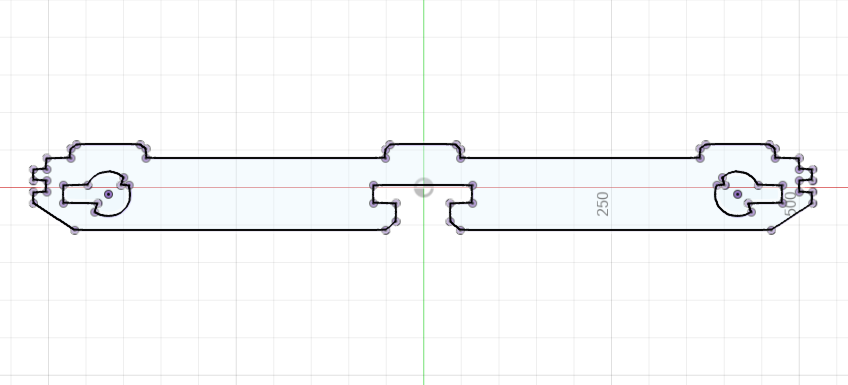
I made some errors in the calculation so the chairs wouldn't fit
Fold out legs

How it looks together


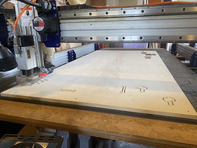
Wood stock
For the assignment I am using 1000 x 2000 x 18 mm plywood boards, some of which have been previously used as A-Frame's for signage and therefore had staples, lanyard and pieces of poster paper that needed to be removed prior to cutting.
Nesting
In CNC term, nesting is the act of reducing cutting time and preserving as much of the wood stock as possible as to not be wasteful. You can find software online to help with this task, but as I was cutting larger pieces that would use the majority of the stock, I chose to nest the pieces myself on V-carve.
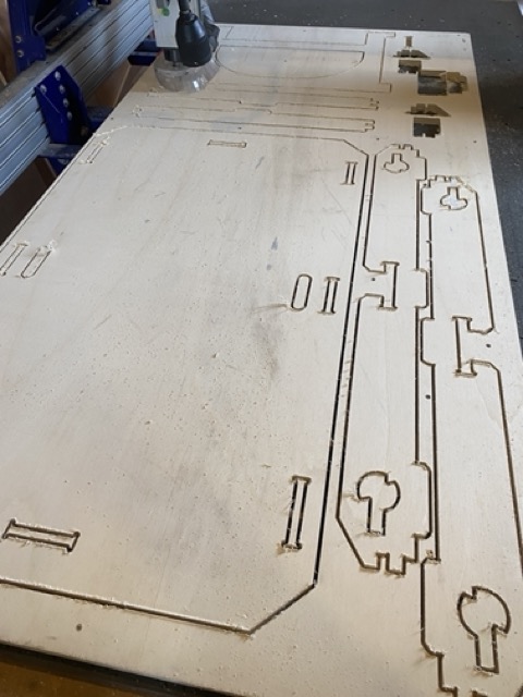
Milling
Before starting to Mill myself and Michelle looked over the V-Carve files making sure paths look good, some changes were made to the chairs as they are multiple pieces in one sheet of wood, so for that there were instances were the tool would pass several times while not milling, time wasting and potentially dangerous should a piece come loose. To do that we used he scissor icon on V-carve to cut sections of the tool path.
Once we had the files ready, I made some test pieces to check the press fit.
Tool path - outside - offset -0.2 - tab 5mm x 3mm
While creating a rectangle vector for the test pieces we made an error, due to the centre of the rectangle being an inside cut this should have been sent in a separate toolpath file ahead of the rectangle. For that reason, once the tool started to cut the inside line, I had to engage the emergency stop. The rectangle came loose and the spindle caused it to burn slightly.
Following on the next week with more caution, I started to mill using slightly bigger tabs and a reduced offset of -0.1mm for the outside lines.
Results
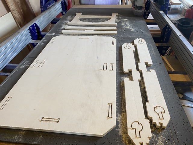
Hero shot
Reflection
A few things didn't go according to plan and you can se why you need absolute concentration while not only using the CNC, primarily taking in as much as the safety notifications as possible.
-
I made a last minute adjustment to the v-carve drawing to include a joint that I wanted to cut out of a spare part of the wood stock. This resulted in a segment becoming loose and me having to hit the emergency stop. What happened? The cutting format was wrong, I had started with an outside line before cutting out the centre bone shape for the joint. This resulted in the square piece becoming loose and jamming against the spindle. Luckily I pressed the emergency stop before it dislodged at 18000RPM.
-
I also made some design errors, the inside legs have too much space between the underside of the table and can therefore move from side to side which isn't ideal. I think i can remedy this with some acrylic to bolster the leg joints and reduce the gap and therefore sliding.
-
I will name the chair a confidence tester, as you need to either be light or very confident when sitting in it. It is not structurally sound and the thin back legs bend when I sit down in it. I would make the thicker if I were to design the chair again.
Learning outcomes
- Demonstrate 2D design development for CNC milling production
- Describe workflows for CNC milling production
Have you answered these questions?
- Linked to the group assignment page [x]
- Documented how you designed your object (something big) [x]
- Documented how you made your CAM-toolpath [x]
- Documented how you made something BIG (setting up the machine, using fixings, testing joints, adjusting feeds and speeds, depth of cut etc.) [x]
- Described problems and how you fixed them [x]
- Included your design files and 'hero shot' of your final product [x]