13. Networking & communication
| Day | Supply | Tasks | |
|---|---|---|---|
| Thursday | 10:00-13:00 | Lecture from Erwin | [x] |
| 14:00-18:00 | Group assignment | [x] | |
| Friday | 09:00-11:30 | Electronics design | [x] |
| 13:00-17:00 | Milling and testing | [x] | |
| Saturday | 09:00-12:00 | Set up telegram bot | working progress |
| Sunday | 17:00-20:00 | Communicate with micro-controller | [x] |
| Monday | 9:00-17:30 | Final project design | [x] |
| 20:00-23:00 | Documentation | [x] | |
| Tuesday | 9:00-17:30 | Final project design | [x] |
| 20:00-22:00 | Documentation | [x] | |
| Wednesday | 9:00-11:00 | Documentation | [x] |
Group assignment:
- Send a message between two projects
- Document your work to the group work page and reflect on your individual page what you learned
For the group assignment Vera and I teamed up to scratch our heads and try to send a message to each other. Firstly we tried to connect two arduino boards using the UART protocol where we share a ground and connect two wires crossing over between TX to RX.
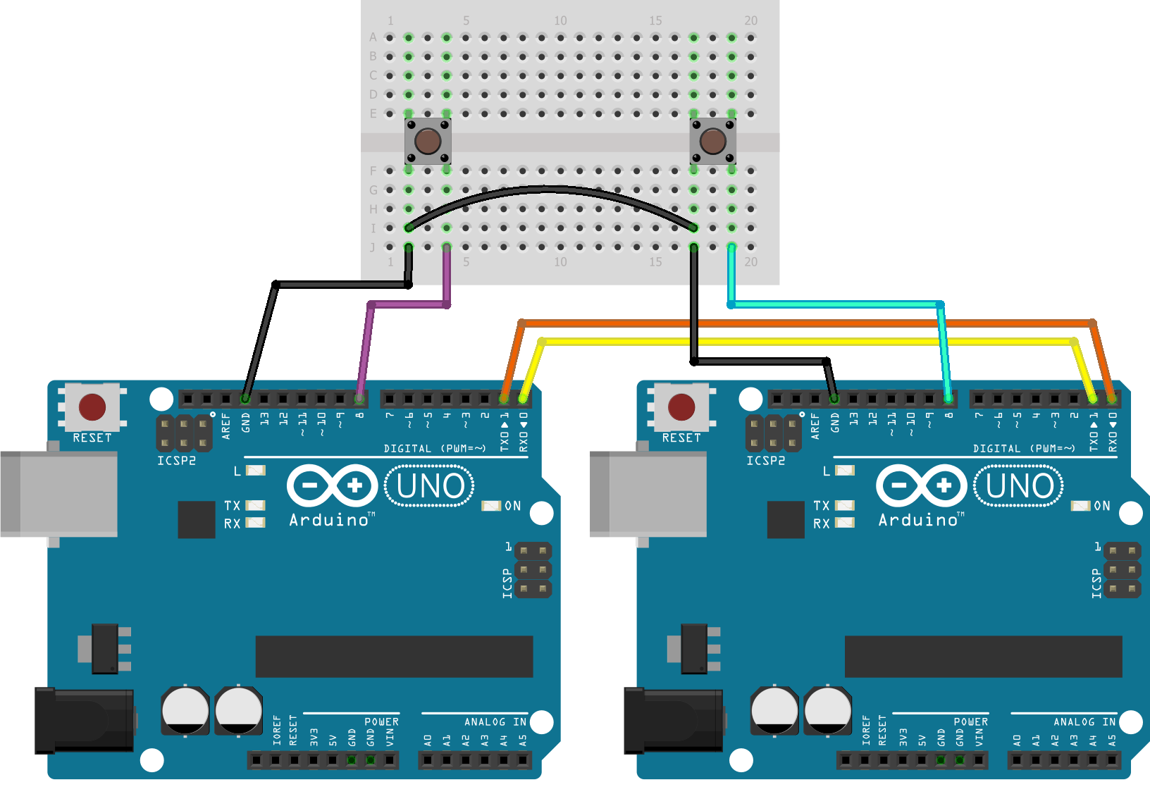
After setting up the boards per the diagram above, we downloaded the libraries, selected the board, board rate and then went about programming. I used the code below, which would change the serial monitor from 0 to 1 when pressing the button. It kind of worked, but we both had a lot of issues either uploading the code or with my computer freezing.
//Receiver Code

#define PIN_LED 3
char str[4];
byte rcvData = 31;

void setup() {
  pinMode(PIN_LED, OUTPUT);
  Serial.begin(9600);
  Serial1.begin(9600);
}

void loop() {
  analogWrite(PIN_LED, rcvData);
  int i=0;

  if (Serial1.available()) {
    delay(100); //allows all serial sent to be received together
    while(Serial1.available() && i<4) {
      str[i++] = Serial1.read();
    }
    str[i++]='\0';
  }

  if(i>0) {
    Serial.println(str,4);
  }
}
Connecting two micro controllers via bluetooth
We then tried to connect and send a message via bluetooth using our own ESP32C micro controllers, I found a nice tutorial with code you can take a look Here.
To connect we have to set one device as a server and the other as a client in the programme. We then used the arduino IDE to upload the code and then open the serial monitor, from here we can see if the boards are connected. Once both micro controllers were ready all we had to do to connect was simultaneously press the reset button of the ESP32's.

Individual assignment:
- design, build and connect wired or wireless node(s) with network or bus addresses and a local interface
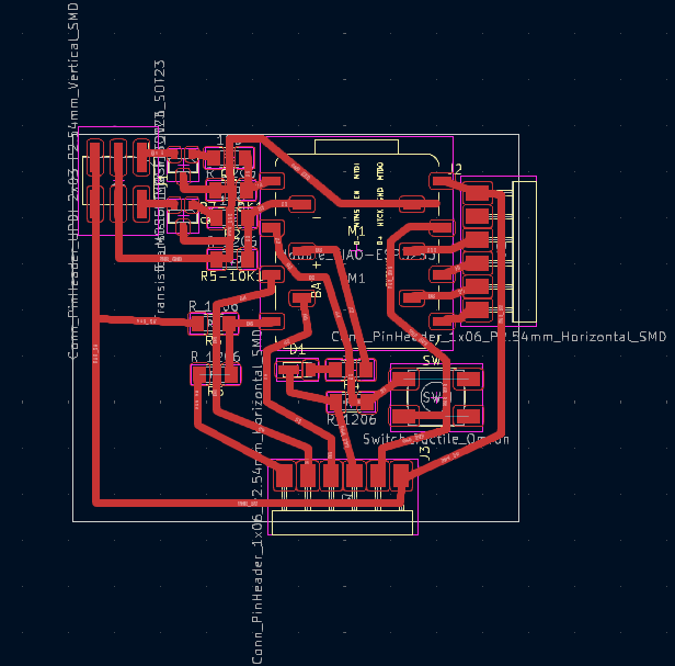
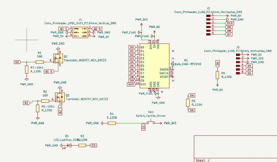
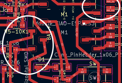
So for this week my plan was to connect my ESP32C3 to an app on my phone and have data sent via WIFI or bluetooth, but apparently that was too easy, so I had to play around with I2C instead. For this I had to design a new pcb as my SCL, SCA pins were not available on my previous boards. I thought this would be a good idea anyway, I could connect the mosfet's with pull down resistors and test them and make some adjustments to the previous weeks design, like having the correct layout for the ESP so it's removable and not surface mount. Here is the updated design, with 10kohm resistors between output pin and ground and a 100ohm resistor between the gate and output pin.
I2C
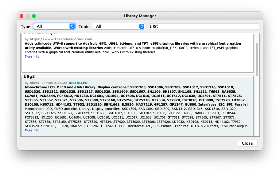
To "play" with the I2C protocol I was given an SSD1306 OLED I2C 128x64 Display, quite a small but once you get it working, it a really nice screen for it size with some cool graphics. The connections are pretty simple, as with any node on the I2C bus, you just have to connect power, GND and then just two wires for SCL(clock/baud rate) and SCA(Serial Data). After that you need to download the library for your device, for the OLED I found two libraries, the U8G2 and the ADA FRUIT SSD1306.
Then I found some code on the arduino libraries and tried my best to get a dud screen to say something, It did'nt work. I managed to find another OLED in the workshop and after plugging in a rebooting the code I got a hello world! Unbelievable.

Source code
/*

  HelloWorld.ino

  "Hello World" version for U8x8 API

  Universal 8bit Graphics Library (https://github.com/olikraus/u8g2/)

  Copyright (c) 2016, olikraus@gmail.com
  All rights reserved.

  Redistribution and use in source and binary forms, with or without modification,
  are permitted provided that the following conditions are met:

  * Redistributions of source code must retain the above copyright notice, this list
    of conditions and the following disclaimer.

  * Redistributions in binary form must reproduce the above copyright notice, this
    list of conditions and the following disclaimer in the documentation and/or other
    materials provided with the distribution.

  THIS SOFTWARE IS PROVIDED BY THE COPYRIGHT HOLDERS AND
  CONTRIBUTORS "AS IS" AND ANY EXPRESS OR IMPLIED WARRANTIES,
  INCLUDING, BUT NOT LIMITED TO, THE IMPLIED WARRANTIES OF
  MERCHANTABILITY AND FITNESS FOR A PARTICULAR PURPOSE ARE
  DISCLAIMED. IN NO EVENT SHALL THE COPYRIGHT HOLDER OR
  CONTRIBUTORS BE LIABLE FOR ANY DIRECT, INDIRECT, INCIDENTAL,
  SPECIAL, EXEMPLARY, OR CONSEQUENTIAL DAMAGES (INCLUDING, BUT
  NOT LIMITED TO, PROCUREMENT OF SUBSTITUTE GOODS OR SERVICES;
  LOSS OF USE, DATA, OR PROFITS; OR BUSINESS INTERRUPTION) HOWEVER
  CAUSED AND ON ANY THEORY OF LIABILITY, WHETHER IN CONTRACT,
  STRICT LIABILITY, OR TORT (INCLUDING NEGLIGENCE OR OTHERWISE)
  ARISING IN ANY WAY OUT OF THE USE OF THIS SOFTWARE, EVEN IF
  ADVISED OF THE POSSIBILITY OF SUCH DAMAGE.

*/

#include <Arduino.h>
#include <U8x8lib.h>

#ifdef U8X8_HAVE_HW_SPI
#include <SPI.h>
#endif

// Please UNCOMMENT one of the constructor lines below
// U8x8 Constructor List
// The complete list is available here: https://github.com/olikraus/u8g2/wiki/u8x8setupcpp
// Please update the pin numbers according to your setup. Use U8X8_PIN_NONE if the reset pin is not connected
//U8X8_NULL u8x8;   // null device, a 8x8 pixel display which does nothing
//U8X8_SSD1306_128X64_NONAME_4W_SW_SPI u8x8(/* clock=*/ 13, /* data=*/ 11, /* cs=*/ 10, /* dc=*/ 9, /* reset=*/ 8);
//U8X8_SSD1306_128X64_NONAME_4W_HW_SPI u8x8(/* cs=*/ 6, /* dc=*/ 4, /* reset=*/ 12);    // Arduboy (DevKit)
//U8X8_SSD1306_128X64_NONAME_4W_HW_SPI u8x8(/* cs=*/ 12, /* dc=*/ 4, /* reset=*/ 6);    // Arduboy 10 (Production, Kickstarter Edition)
//U8X8_SSD1306_128X64_NONAME_4W_HW_SPI u8x8(/* cs=*/ 10, /* dc=*/ 9, /* reset=*/ 8);
//U8X8_SSD1306_128X64_NONAME_3W_SW_SPI u8x8(/* clock=*/ 13, /* data=*/ 11, /* cs=*/ 10, /* reset=*/ 8);
//U8X8_SSD1306_128X64_NONAME_3W_HW_SPI u8x8(/* cs=*/ 10, /* reset=*/ 8);
//U8X8_SSD1306_128X64_NONAME_HW_I2C u8x8(/* reset=*/ U8X8_PIN_NONE);
U8X8_SSD1306_128X64_ALT0_HW_I2C u8x8(/* reset=*/ U8X8_PIN_NONE);          // same as the NONAME variant, but may solve the "every 2nd line skipped" problem
//U8X8_SSD1306_128X64_NONAME_SW_I2C u8x8(/* clock=*/ 2, /* data=*/ 0, /* reset=*/ U8X8_PIN_NONE);         // Digispark ATTiny85
//U8X8_SSD1306_128X64_NONAME_SW_I2C u8x8(/* clock=*/ SCL, /* data=*/ SDA, /* reset=*/ U8X8_PIN_NONE);   // OLEDs without Reset of the Display
//U8X8_SSD1306_128X64_VCOMH0_4W_HW_SPI u8x8(/* cs=*/ 10, /* dc=*/ 9, /* reset=*/ 8);        // same as the NONAME variant, but maximizes setContrast() range
//U8X8_SSD1306_128X64_ALT0_4W_HW_SPI u8x8(/* cs=*/ 10, /* dc=*/ 9, /* reset=*/ 8);      // same as the NONAME variant, but may solve the "every 2nd line skipped" problem
//U8X8_SSD1306_102X64_EA_OLEDS102_4W_HW_SPI u8x8(/* cs=*/ 10, /* dc=*/ 9, /* reset=*/ 8);       // same as the NONAME variant, but may solve the "every 2nd line skipped" problem
//U8X8_SSD1312_128X64_NONAME_4W_SW_SPI u8x8(/* clock=*/ 13, /* data=*/ 11, /* cs=*/ 10, /* dc=*/ 9, /* reset=*/ 8);
//U8X8_SSD1312_128X64_NONAME_SW_I2C u8x8(/* clock=*/ SCL, /* data=*/ SDA, /* reset=*/ 8);
//U8X8_SSD1312_128X64_NONAME_HW_I2C u8x8(/* reset=*/ U8X8_PIN_NONE);
//U8X8_SH1106_128X64_NONAME_4W_HW_SPI u8x8(/* cs=*/ 10, /* dc=*/ 9, /* reset=*/ 8);
//U8X8_SH1106_128X64_NONAME_HW_I2C u8x8(/* reset=*/ U8X8_PIN_NONE);
//U8X8_SH1106_128X64_VCOMH0_4W_HW_SPI u8x8(/* cs=*/ 10, /* dc=*/ 9, /* reset=*/ 8);     // same as the NONAME variant, but maximizes setContrast() range
//U8X8_SH1106_128X64_WINSTAR_4W_HW_SPI u8x8(/* cs=*/ 10, /* dc=*/ 9, /* reset=*/ 8);        // same as the NONAME variant, but uses updated SH1106 init sequence
//U8X8_SH1106_128X32_VISIONOX_HW_I2C u8x8(/* reset=*/ U8X8_PIN_NONE);
//U8X8_SH1106_128X32_VISIONOX_4W_HW_SPI u8x8(/* cs=*/ 10, /* dc=*/ 9, /* reset=*/ 8);
//U8X8_SH1106_72X40_WISE_4W_HW_SPI u8x8(/* cs=*/ 10, /* dc=*/ 9, /* reset=*/ 8);
//U8X8_SH1107_64X128_4W_HW_SPI u8x8(/* cs=*/ 10, /* dc=*/ 9, /* reset=*/ 8);
//U8X8_SH1107_128X128_4W_HW_SPI u8x8(/* cs=*/ 10, /* dc=*/ 9, /* reset=*/ 8);
//U8X8_SH1107_128X128_HW_I2C u8x8(/* reset=*/ 8);
//U8X8_SH1107_128X80_HW_I2C u8x8(/* reset=*/ 8);
//U8X8_SH1107_PIMORONI_128X128_HW_I2C u8x8(/* reset=*/ 8);
//U8X8_SH1107_SEEED_128X128_SW_I2C u8x8(/* clock=*/ SCL, /* data=*/ SDA, /* reset=*/ U8X8_PIN_NONE);
//U8X8_SH1107_SEEED_128X128_HW_I2C u8x8(/* reset=*/ U8X8_PIN_NONE);
//U8X8_SH1107_SEEED_96X96_4W_HW_SPI u8x8(/* cs=*/ 10, /* dc=*/ 9, /* reset=*/ 8);
//U8X8_SH1108_128X160_4W_HW_SPI u8x8(/* cs=*/ 10, /* dc=*/ 9, /* reset=*/ 8);
//U8X8_SH1108_160X160_4W_HW_SPI u8x8(/* cs=*/ 10, /* dc=*/ 9, /* reset=*/ 8);
//U8X8_SSD1306_128X32_UNIVISION_SW_I2C u8x8(/* clock=*/ SCL, /* data=*/ SDA, /* reset=*/ U8X8_PIN_NONE);   // Adafruit Feather ESP8266/32u4 Boards + FeatherWing OLED
//U8X8_SSD1306_128X32_UNIVISION_SW_I2C u8x8(/* clock=*/ 21, /* data=*/ 20, /* reset=*/ U8X8_PIN_NONE);   // Adafruit Feather M0 Basic Proto + FeatherWing OLED
//U8X8_SSD1306_128X32_UNIVISION_HW_I2C u8x8(/* reset=*/ U8X8_PIN_NONE);   // Adafruit ESP8266/32u4/ARM Boards + FeatherWing OLED
//U8X8_SSD1306_128X32_UNIVISION_HW_I2C u8x8(/* reset=*/ U8X8_PIN_NONE, /* clock=*/ SCL, /* data=*/ SDA);   // pin remapping with ESP8266 HW I2C
//U8X8_SSD1306_128X32_WINSTAR_HW_I2C u8x8(/* reset=*/ U8X8_PIN_NONE, /* clock=*/ SCL, /* data=*/ SDA);   // pin remapping with ESP8266 HW I2C
//U8X8_SSD1306_64X48_ER_HW_I2C u8x8(/* reset=*/ U8X8_PIN_NONE);   // EastRising 0.66" OLED breakout board, Uno: A4=SDA, A5=SCL, 5V powered
//U8X8_SSD1306_48X64_WINSTAR_HW_I2C u8x8(/* reset=*/ U8X8_PIN_NONE);
//U8X8_SSD1306_64X32_NONAME_HW_I2C u8x8(/* reset=*/ U8X8_PIN_NONE);
//U8X8_SSD1306_64X32_1F_HW_I2C u8x8(/* reset=*/ U8X8_PIN_NONE);
//U8X8_SSD1306_96X16_ER_HW_I2C u8x8(/* reset=*/ U8X8_PIN_NONE);   // EastRising 0.69"
//U8X8_SSD1306_72X40_ER_HW_I2C u8x8(/* reset=*/ U8X8_PIN_NONE);   // EastRising 0.42"
//U8X8_SSD1306_96X40_HW_I2C u8x8(/* reset=*/ U8X8_PIN_NONE);
//U8X8_SSD1306_96X39_HW_I2C u8x8(/* reset=*/ U8X8_PIN_NONE);
//U8X8_SSD1306_128X64_NONAME_6800 u8x8(13, 11, 2, 3, 4, 5, 6, A4, /*enable=*/ 7, /*cs=*/ 10, /*dc=*/ 9, /*reset=*/ 8);
//U8X8_SSD1306_128X64_NONAME_8080 u8x8(13, 11, 2, 3, 4, 5, 6, A4, /*enable=*/ 7, /*cs=*/ 10, /*dc=*/ 9, /*reset=*/ 8);
//U8X8_SSD1309_128X64_NONAME0_4W_SW_SPI u8x8(/* clock=*/ 13, /* data=*/ 11, /* cs=*/ 10, /* dc=*/ 9, /* reset=*/ 8);
//U8X8_SSD1309_128X64_NONAME0_4W_HW_SPI u8x8(/* cs=*/ 10, /* dc=*/ 9, /* reset=*/ 8);
//U8X8_SSD1309_128X64_NONAME2_4W_SW_SPI u8x8(/* clock=*/ 13, /* data=*/ 11, /* cs=*/ 10, /* dc=*/ 9, /* reset=*/ 8);
//U8X8_SSD1309_128X64_NONAME2_4W_HW_SPI u8x8(/* cs=*/ 10, /* dc=*/ 9, /* reset=*/ 8);
//U8X8_SSD1316_128X32_4W_SW_SPI u8x8(/* clock=*/ 13, /* data=*/ 11, /* cs=*/ 10, /* dc=*/ 9, /* reset=*/ 8);
//U8X8_SSD1316_128X32_4W_HW_SPI u8x8(/* cs=*/ 10, /* dc=*/ 9, /* reset=*/ 8);
//U8X8_SSD1316_96X32_4W_SW_SPI u8x8(/* clock=*/ 13, /* data=*/ 11, /* cs=*/ 10, /* dc=*/ 9, /* reset=*/ 8);
//U8X8_SSD1316_96X32_4W_HW_SPI u8x8(/* cs=*/ 10, /* dc=*/ 9, /* reset=*/ 8);
//U8X8_SSD1317_96X96_4W_SW_SPI u8x8(/* clock=*/ 13, /* data=*/ 11, /* cs=*/ 10, /* dc=*/ 9, /* reset=*/ 8);  // not tested, not confirmed
//U8X8_SSD1317_96X96_4W_HW_SPI u8x8(/* cs=*/ 10, /* dc=*/ 9, /* reset=*/ 8);  // not tested, not confirmed
//U8X8_SSD1318_128X96_4W_SW_SPI u8x8(/* clock=*/ 13, /* data=*/ 11, /* cs=*/ 10, /* dc=*/ 9, /* reset=*/ 8);
//U8X8_SSD1318_128X96_4W_HW_SPI u8x8(/* cs=*/ 10, /* dc=*/ 9, /* reset=*/ 8);
//U8X8_SSD1320_160X132_4W_SW_SPI u8x8(/* clock=*/ 13, /* data=*/ 11, /* cs=*/ 10, /* dc=*/ 9, /* reset=*/ 8);
//U8X8_SSD1320_160X132_4W_HW_SPI u8x8(/* cs=*/ 10, /* dc=*/ 9, /* reset=*/ 8);
//U8X8_SSD1320_160X80_4W_SW_SPI u8x8(/* clock=*/ 13, /* data=*/ 11, /* cs=*/ 10, /* dc=*/ 9, /* reset=*/ 8);
//U8X8_SSD1320_160X80_4W_HW_SPI u8x8(/* cs=*/ 10, /* dc=*/ 9, /* reset=*/ 8);
//U8X8_SSD1322_240X128_4W_SW_SPI u8x8(/* clock=*/ 13, /* data=*/ 11, /* cs=*/ 10, /* dc=*/ 9, /* reset=*/ 8);
//U8X8_SSD1322_NHD_256X64_4W_SW_SPI u8x8(/* clock=*/ 13, /* data=*/ 11, /* cs=*/ 10, /* dc=*/ 9, /* reset=*/ 8);
//U8X8_SSD1322_NHD_256X64_4W_HW_SPI u8x8(/* cs=*/ 10, /* dc=*/ 9, /* reset=*/ 8);
//U8X8_SSD1362_256X64_4W_SW_SPI u8x8(/* clock=*/ 13, /* data=*/ 11, /* cs=*/ 10, /* dc=*/ 9, /* reset=*/ 8);
//U8X8_SSD1362_256X64_4W_HW_SPI u8x8(/* cs=*/ 10, /* dc=*/ 9, /* reset=*/ 8);
//U8X8_SSD1362_206X36_4W_SW_SPI u8x8(/* clock=*/ 13, /* data=*/ 11, /* cs=*/ 10, /* dc=*/ 9, /* reset=*/ 8);
//U8X8_SSD1362_206X36_4W_HW_SPI u8x8(/* cs=*/ 10, /* dc=*/ 9, /* reset=*/ 8);
//U8X8_SSD1322_NHD_128X64_4W_SW_SPI u8x8(/* clock=*/ 13, /* data=*/ 11, /* cs=*/ 10, /* dc=*/ 9, /* reset=*/ 8);
//U8X8_SSD1322_NHD_128X64_4W_HW_SPI u8x8(/* cs=*/ 10, /* dc=*/ 9, /* reset=*/ 8);
//U8X8_SSD1325_NHD_128X64_4W_SW_SPI u8x8(/* clock=*/ 13, /* data=*/ 11, /* cs=*/ 10, /* dc=*/ 9, /* reset=*/ 8);
//U8X8_SSD1325_NHD_128X64_4W_HW_SPI u8x8(/* cs=*/ 10, /* dc=*/ 9, /* reset=*/ 8);
//U8X8_SSD0323_OS128064_4W_SW_SPI u8x8(/* clock=*/ 13, /* data=*/ 11, /* cs=*/ 10, /* dc=*/ 9, /* reset=*/ 8);
//U8X8_SSD0323_OS128064_4W_HW_SPI u8x8(/* cs=*/ 10, /* dc=*/ 9, /* reset=*/ 8);
//U8X8_SSD1326_ER_256X32_4W_SW_SPI u8x8(/* clock=*/ 13, /* data=*/ 11, /* cs=*/ 10, /* dc=*/ 9, /* reset=*/ 8);         // experimental driver for ER-OLED018-1
//U8X8_SSD1327_SEEED_96X96_SW_I2C u8x8(/* clock=*/ SCL, /* data=*/ SDA, /* reset=*/ U8X8_PIN_NONE); // Seeedstudio Grove OLED 96x96
//U8X8_SSD1327_SEEED_96X96_HW_I2C u8x8(/* reset=*/ U8X8_PIN_NONE);  // Seeedstudio Grove OLED 96x96
//U8X8_SSD1327_EA_W128128_4W_SW_SPI u8x8(/* clock=*/ 13, /* data=*/ 11, /* cs=*/ 10, /* dc=*/ 9, /* reset=*/ 8);
//U8X8_SSD1327_EA_W128128_4W_HW_SPI u8x8(/* cs=*/ 10, /* dc=*/ 9, /* reset=*/ 8);
//U8X8_SSD1327_MIDAS_128X128_4W_SW_SPI u8x8(/* clock=*/ 13, /* data=*/ 11, /* cs=*/ 10, /* dc=*/ 9, /* reset=*/ 8);
//U8X8_SSD1327_MIDAS_128X128_4W_HW_SPI u8x8(/* cs=*/ 10, /* dc=*/ 9, /* reset=*/ 8);
//U8X8_SSD1327_ZJY_128X128_4W_SW_SPI u8x8(/* clock=*/ 13, /* data=*/ 11, /* cs=*/ 10, /* dc=*/ 9, /* reset=*/ 8);
//U8X8_SSD1327_ZJY_128X128_4W_HW_SPI u8x8(/* cs=*/ 10, /* dc=*/ 9, /* reset=*/ 8);
//U8X8_SSD1327_WS_128X128_4W_SW_SPI u8x8(/* clock=*/ 13, /* data=*/ 11, /* cs=*/ 10, /* dc=*/ 9, /* reset=*/ 8);
//U8X8_SSD1327_WS_128X128_4W_HW_SPI u8x8(/* cs=*/ 10, /* dc=*/ 9, /* reset=*/ 8);
//U8X8_SSD1327_VISIONOX_128X96_4W_SW_SPI u8x8(/* clock=*/ 13, /* data=*/ 11, /* cs=*/ 10, /* dc=*/ 9, /* reset=*/ 8);
//U8X8_SSD1327_VISIONOX_128X96_4W_HW_SPI u8x8(/* cs=*/ 10, /* dc=*/ 9, /* reset=*/ 8);
//U8X8_SSD1329_128X96_NONAME_4W_SW_SPI u8x8(/* clock=*/ 13, /* data=*/ 11, /* cs=*/ 10, /* dc=*/ 9, /* reset=*/ 8);
//U8X8_SSD1329_128X96_NONAME_4W_HW_SPI u8x8(/* cs=*/ 10, /* dc=*/ 9, /* reset=*/ 8);
//U8X8_SSD1329_96X96_NONAME_4W_SW_SPI u8x8(/* clock=*/ 13, /* data=*/ 11, /* cs=*/ 10, /* dc=*/ 9, /* reset=*/ 8);
//U8X8_SSD1329_96X96_NONAME_4W_HW_SPI u8x8(/* cs=*/ 10, /* dc=*/ 9, /* reset=*/ 8);
//U8X8_SSD1329_96X96_NONAME_4W_HW_SPI u8x8(/* cs=*/ A4, /* dc=*/ A2, /* reset=*/ U8X8_PIN_NONE); //  Adafruit Feather 32u4 Basic Proto
//U8X8_SSD1305_128X32_NONAME_4W_SW_SPI u8x8(/* clock=*/ 13, /* data=*/ 11, /* cs=*/ 10, /* dc=*/ 9, /* reset=*/ 8);
//U8X8_SSD1305_128X32_NONAME_4W_HW_SPI u8x8(/* cs=*/ 10, /* dc=*/ 9, /* reset=*/ 8);
//U8X8_SSD1305_128X32_ADAFRUIT_4W_SW_SPI u8x8(/* clock=*/ 13, /* data=*/ 11, /* cs=*/ 10, /* dc=*/ 9, /* reset=*/ 8);
//U8X8_SSD1305_128X32_ADAFRUIT_4W_HW_SPI u8x8(/* cs=*/ 10, /* dc=*/ 9, /* reset=*/ 8);
//U8X8_SSD1305_128X64_ADAFRUIT_4W_SW_SPI u8x8(/* clock=*/ 13, /* data=*/ 11, /* cs=*/ 10, /* dc=*/ 9, /* reset=*/ 8);
//U8X8_SSD1305_128X64_ADAFRUIT_4W_HW_SPI u8x8(/* cs=*/ 10, /* dc=*/ 9, /* reset=*/ 8);
//U8X8_SSD1305_128X64_RAYSTAR_4W_SW_SPI u8x8(/* clock=*/ 13, /* data=*/ 11, /* cs=*/ 10, /* dc=*/ 9, /* reset=*/ 8);
//U8X8_SSD1305_128X64_RAYSTAR_4W_HW_SPI u8x8(/* cs=*/ 10, /* dc=*/ 9, /* reset=*/ 8);
//U8X8_KS0108_128X64 u8x8(8, 9, 10, 11, 4, 5, 6, 7, /*enable=*/ 18, /*dc=*/ 17, /*cs0=*/ 14, /*cs1=*/ 15, /*cs2=*/ U8X8_PIN_NONE, /* reset=*/  U8X8_PIN_NONE);  // Set R/W to low!
//U8X8_KS0108_ERM19264 u8x8(8, 9, 10, 11, 4, 5, 6, 7, /*enable=*/ 18, /*dc=*/ 17, /*cs0=*/ 14, /*cs1=*/ 15, /*cs2=*/ 16, /* reset=*/  U8X8_PIN_NONE);   // Set R/W to low!
//U8X8_HD44102_100X64 u8x8(4, 5, 6, 7, 8, 9, 10, 11, /*enable=*/ 2, /*dc=*/ 3, /*cs0=*/ A0, /*cs1=*/ A1, /*cs2=*/ A2, /* reset=*/  U8X8_PIN_NONE);  // Set R/W to low!
//U8X8_T7932_150X32 u8x8(4, 5, 6, 7, 8, 9, 10, 11, /*enable=*/ 2, /*dc=*/ 3, /*cs0=*/ A0, /*cs1=*/ A1, /*cs2=*/ A2, /* reset=*/  U8X8_PIN_NONE);    // Set R/W to low!
//U8X8_UC1701_EA_DOGS102_4W_SW_SPI u8x8(/* clock=*/ 13, /* data=*/ 11, /* cs=*/ 10, /* dc=*/ 9, /* reset=*/ 8);
//U8X8_UC1701_EA_DOGS102_4W_HW_SPI u8x8(/* cs=*/ 10, /* dc=*/ 9, /* reset=*/ 8);
//U8X8_PCD8544_84X48_4W_SW_SPI u8x8(/* clock=*/ 13, /* data=*/ 11, /* cs=*/ 10, /* dc=*/ 9, /* reset=*/ 8); // Nokia 5110 Display
//U8X8_PCD8544_84X48_4W_HW_SPI u8x8(/* cs=*/ 10, /* dc=*/ 9, /* reset=*/ 8);                            // Nokia 5110 Display
//U8X8_PCF8812_96X65_4W_SW_SPI u8x8(/* clock=*/ 13, /* data=*/ 11, /* cs=*/ 10, /* dc=*/ 9, /* reset=*/ 8); // Could be also PCF8814
//U8X8_PCF8812_96X65_4W_HW_SPI u8x8(/* cs=*/ 10, /* dc=*/ 9, /* reset=*/ 8);            // Could be also PCF8814
//U8X8_HX1230_96X68_3W_SW_SPI u8x8(/* clock=*/ 13, /* data=*/ 11, /* cs=*/ 10, /* reset=*/ 8);
//U8X8_HX1230_96X68_4W_SW_SPI u8x8(/* clock=*/ 13, /* data=*/ 11, /* cs=*/ 10, /* dc=*/ 9, /* reset=*/ 8);
//U8X8_ST7528_ERC16064_4W_SW_SPI u8x8(/* clock=*/ 13, /* data=*/ 11, /* cs=*/ 10, /* dc=*/ 9, /* reset=*/ 8);
//U8X8_ST7528_ERC16064_4W_HW_SPI u8x8(/* cs=*/ 10, /* dc=*/ 9, /* reset=*/ 8);
//U8X8_ST7539_192X64_4W_SW_SPI u8x8(/* clock=*/ 13, /* data=*/ 11, /* cs=*/ 10, /* dc=*/ 9, /* reset=*/ 8);
//U8X8_ST7539_192X64_4W_HW_SPI u8x8(/* cs=*/ 10, /* dc=*/ 9, /* reset=*/ 8);
//U8X8_ST7565_EA_DOGM128_4W_SW_SPI u8x8(/* clock=*/ 13, /* data=*/ 11, /* cs=*/ 10, /* dc=*/ 9, /* reset=*/ 8);
//U8X8_ST7565_EA_DOGM128_4W_HW_SPI u8x8(/* cs=*/ 10, /* dc=*/ 9, /* reset=*/ 8);
//U8X8_ST7565_64128N_4W_SW_SPI u8x8(/* clock=*/ 13, /* data=*/ 11, /* cs=*/ 10, /* dc=*/ 9, /* reset=*/ 8);
//U8X8_ST7565_64128N_4W_HW_SPI u8x8(/* cs=*/ 10, /* dc=*/ 9, /* reset=*/ 8);
//U8X8_ST7565_EA_DOGM132_4W_SW_SPI u8x8(/* clock=*/ 13, /* data=*/ 11, /* cs=*/ 10, /* dc=*/ 9, /* reset=*/ U8X8_PIN_NONE); // DOGM132 Shield
//U8X8_ST7565_EA_DOGM132_4W_HW_SPI u8x8(/* cs=*/ 10, /* dc=*/ 9, /* reset=*/ U8X8_PIN_NONE);    // DOGM132 Shield
//U8X8_ST7565_ZOLEN_128X64_4W_SW_SPI u8x8(/* clock=*/ 13, /* data=*/ 11, /* cs=*/ 10, /* dc=*/ 9, /* reset=*/ 8);
//U8X8_ST7565_ZOLEN_128X64_4W_HW_SPI u8x8(/* cs=*/ 10, /* dc=*/ 9, /* reset=*/ 8);
//U8X8_ST7565_LM6059_4W_SW_SPI u8x8(/* clock=*/ 13, /* data=*/ 11, /* cs=*/ 10, /* dc=*/ 9, /* reset=*/ 8); // Adafruit ST7565 GLCD
//U8X8_ST7565_LM6059_4W_HW_SPI u8x8(/* cs=*/ 10, /* dc=*/ 9, /* reset=*/ 8);        // Adafruit ST7565 GLCD
//U8X8_ST7565_KS0713_4W_SW_SPI u8x8(/* clock=*/ 13, /* data=*/ 11, /* cs=*/ 10, /* dc=*/ 9, /* reset=*/ 8); // KS0713 controller
//U8X8_ST7565_KS0713_4W_HW_SPI u8x8(/* cs=*/ 10, /* dc=*/ 9, /* reset=*/ 8);        // KS0713 controller
//U8X8_ST7565_LX12864_4W_SW_SPI u8x8(/* clock=*/ 13, /* data=*/ 11, /* cs=*/ 10, /* dc=*/ 9, /* reset=*/ 8);
//U8X8_ST7565_LX12864_4W_HW_SPI u8x8(/* cs=*/ 10, /* dc=*/ 9, /* reset=*/ 8);
//U8X8_ST7565_ERC12864_4W_SW_SPI u8x8(/* clock=*/ 13, /* data=*/ 11, /* cs=*/ 10, /* dc=*/ 9, /* reset=*/ 8);
//U8X8_ST7565_ERC12864_4W_HW_SPI u8x8(/* cs=*/ 10, /* dc=*/ 9, /* reset=*/ 8);
//U8X8_ST7565_ERC12864_ALT_4W_SW_SPI u8x8(/* clock=*/ 13, /* data=*/ 11, /* cs=*/ 10, /* dc=*/ 9, /* reset=*/ 8); // contrast improved version for ERC12864
//U8X8_ST7565_ERC12864_ALT_4W_HW_SPI u8x8(/* cs=*/ 10, /* dc=*/ 9, /* reset=*/ 8);  // contrast improved version for ERC12864
//U8X8_ST7565_NHD_C12832_4W_SW_SPI u8x8(/* clock=*/ 13, /* data=*/ 11, /* cs=*/ 10, /* dc=*/ 9, /* reset=*/ 8);
//U8X8_ST7565_NHD_C12832_4W_HW_SPI u8x8(/* cs=*/ 10, /* dc=*/ 9, /* reset=*/ 8);
//U8X8_ST7565_NHD_C12864_4W_SW_SPI u8x8(/* clock=*/ 13, /* data=*/ 11, /* cs=*/ 10, /* dc=*/ 9, /* reset=*/ 8);
//U8X8_ST7565_NHD_C12864_4W_HW_SPI u8x8(/* cs=*/ 10, /* dc=*/ 9, /* reset=*/ 8);
//U8X8_ST7565_JLX12864_4W_SW_SPI u8x8(/* clock=*/ 13, /* data=*/ 11, /* cs=*/ 10, /* dc=*/ 9, /* reset=*/ 8);
//U8X8_ST7565_JLX12864_4W_HW_SPI u8x8(/* cs=*/ 10, /* dc=*/ 9, /* reset=*/ 8);
//U8X8_ST7567_PI_132X64_4W_SW_SPI u8x8(/* clock=*/ 13, /* data=*/ 11, /* cs=*/ 7, /* dc=*/ 9, /* reset=*/ 8);  // Pax Instruments Shield, LCD_BL=6
//U8X8_ST7567_PI_132X64_4W_HW_SPI u8x8(/* cs=*/ 7, /* dc=*/ 9, /* reset=*/ 8);  // Pax Instruments Shield, LCD_BL=6
//U8X8_ST7567_JLX12864_4W_SW_SPI u8x8(/* clock=*/ 13, /* data=*/ 11, /* cs=*/ 7, /* dc=*/ 9, /* reset=*/ 8);
//U8X8_ST7567_JLX12864_4W_HW_SPI u8x8(/* cs=*/ 7, /* dc=*/ 9, /* reset=*/ 8);
//U8X8_ST7567_122X32_4W_SW_SPI u8x8(/* clock=*/ 13, /* data=*/ 11, /* cs=*/ 7, /* dc=*/ 9, /* reset=*/ 8);
//U8X8_ST7567_122X32_4W_HW_SPI u8x8(/* cs=*/ 7, /* dc=*/ 9, /* reset=*/ 8);
//U8X8_ST7567_OS12864_4W_SW_SPI u8x8(/* clock=*/ 13, /* data=*/ 11, /* cs=*/ 7, /* dc=*/ 9, /* reset=*/ 8);
//U8X8_ST7567_OS12864_4W_HW_SPI u8x8(/* cs=*/ 7, /* dc=*/ 9, /* reset=*/ 8);
//U8X8_ST7567_ENH_DG128064_4W_SW_SPI u8x8(/* clock=*/ 13, /* data=*/ 11, /* cs=*/ 10, /* dc=*/ 9, /* reset=*/ 8);
//U8X8_ST7567_ENH_DG128064_4W_HW_SPI u8x8(/* cs=*/ 10, /* dc=*/ 9, /* reset=*/ 8);
//U8X8_ST7567_ENH_DG128064I_4W_SW_SPI u8x8(/* clock=*/ 13, /* data=*/ 11, /* cs=*/ 10, /* dc=*/ 9, /* reset=*/ 8);
//U8X8_ST7567_ENH_DG128064I_4W_HW_SPI u8x8(/* cs=*/ 10, /* dc=*/ 9, /* reset=*/ 8);
//U8X8_ST7567_64X32_HW_I2C u8x8(/* reset=*/ U8X8_PIN_NONE);
//U8X8_ST7567_HEM6432_HW_I2C u8x8(/* reset=*/ U8X8_PIN_NONE);
//U8X8_ST7567_ERC13232_4W_SW_SPI u8x8(/* clock=*/ 13, /* data=*/ 11, /* cs=*/ 10, /* dc=*/ 9, /* reset=*/ 8);
//U8X8_ST7567_ERC13232_4W_HW_SPI u8x8(/* cs=*/ 10, /* dc=*/ 9, /* reset=*/ 8);
//U8X8_ST7571_128X128_4W_SW_SPI u8x8(/* clock=*/ 13, /* data=*/ 11, /* cs=*/ 10, /* dc=*/ 9, /* reset=*/ 8);
//U8X8_ST7571_128X128_4W_HW_SPI u8x8(/* cs=*/ 10, /* dc=*/ 9, /* reset=*/ 8);
//U8X8_ST7571_128X96_4W_SW_SPI u8x8(/* clock=*/ 13, /* data=*/ 11, /* cs=*/ 10, /* dc=*/ 9, /* reset=*/ 8);
//U8X8_ST7571_128X96_4W_HW_SPI u8x8(/* cs=*/ 10, /* dc=*/ 9, /* reset=*/ 8);
//U8X8_ST75160_JM16096_4W_SW_SPI u8x8( /* clock=*/ 13, /* data=*/ 11, /* cs=*/ 10, /* dc=*/ 9, /* reset=*/ 8);
//U8X8_ST75160_JM16096_4W_HW_SPI u8x8(/* cs=*/ 10, /* dc=*/ 9, /* reset=*/ 8);
//U8X8_ST75256_JLX172104_4W_SW_SPI u8x8( /* clock=*/ 13, /* data=*/ 11, /* cs=*/ 10, /* dc=*/ 9, /* reset=*/ 8);
//U8X8_ST75256_JLX172104_4W_HW_SPI u8x8(/* cs=*/ 10, /* dc=*/ 9, /* reset=*/ 8);
//U8X8_ST75256_JLX19296_4W_SW_SPI u8x8( /* clock=*/ 13, /* data=*/ 11, /* cs=*/ 10, /* dc=*/ 9, /* reset=*/ 8);
//U8X8_ST75256_JLX19296_4W_HW_SPI u8x8(/* cs=*/ 10, /* dc=*/ 9, /* reset=*/ 8);
//U8X8_ST75256_JLX16080_4W_SW_SPI u8x8( /* clock=*/ 13, /* data=*/ 11, /* cs=*/ 10, /* dc=*/ 9, /* reset=*/ 8);
//U8X8_ST75256_JLX16080_4W_HW_SPI u8x8(/* cs=*/ 10, /* dc=*/ 9, /* reset=*/ 8);
//U8X8_ST75256_JLX256128_4W_SW_SPI u8x8( /* clock=*/ 13, /* data=*/ 11, /* cs=*/ 10, /* dc=*/ 9, /* reset=*/ 8);
//U8X8_ST75256_JLX256128_4W_HW_SPI u8x8(/* cs=*/ 10, /* dc=*/ 9, /* reset=*/ 8);
//U8X8_ST75256_WO256X128_4W_SW_SPI u8x8( /* clock=*/ 13, /* data=*/ 11, /* cs=*/ 10, /* dc=*/ 9, /* reset=*/ 8);
//U8X8_ST75256_WO256X128_4W_HW_SPI u8x8(/* cs=*/ 10, /* dc=*/ 9, /* reset=*/ 8);
//U8X8_ST75256_JLX256160_4W_SW_SPI u8x8( /* clock=*/ 13, /* data=*/ 11, /* cs=*/ 10, /* dc=*/ 9, /* reset=*/ 8);
//U8X8_ST75256_JLX256160_4W_HW_SPI u8x8(/* cs=*/ 10, /* dc=*/ 9, /* reset=*/ 8);
//U8X8_ST75256_JLX256160M_4W_SW_SPI u8x8( /* clock=*/ 13, /* data=*/ 11, /* cs=*/ 10, /* dc=*/ 9, /* reset=*/ 8);
//U8X8_ST75256_JLX256160M_4W_HW_SPI u8x8(/* cs=*/ 10, /* dc=*/ 9, /* reset=*/ 8);
//U8X8_ST75256_JLX256160_ALT_4W_SW_SPI u8x8( /* clock=*/ 13, /* data=*/ 11, /* cs=*/ 10, /* dc=*/ 9, /* reset=*/ 8);
//U8X8_ST75256_JLX256160_ALT_4W_HW_SPI u8x8(/* cs=*/ 10, /* dc=*/ 9, /* reset=*/ 8);
//U8X8_ST75256_JLX240160_4W_SW_SPI u8x8( /* clock=*/ 13, /* data=*/ 11, /* cs=*/ 10, /* dc=*/ 9, /* reset=*/ 8);
//U8X8_ST75256_JLX240160_4W_HW_SPI u8x8(/* cs=*/ 10, /* dc=*/ 9, /* reset=*/ 8);
//U8X8_ST75256_JLX25664_2ND_HW_I2C u8x8(/* reset=*/ 8); // Due, 2nd I2C
//U8X8_ST75320_JLX320240_4W_SW_SPI u8x8( /* clock=*/ 13, /* data=*/ 11, /* cs=*/ 10, /* dc=*/ 9, /* reset=*/ 8);
//U8X8_ST75320_JLX320240_4W_HW_SPI u8x8(/* cs=*/ 10, /* dc=*/ 9, /* reset=*/ 8);
//U8X8_NT7534_TG12864R_4W_SW_SPI u8x8(/* clock=*/ 13, /* data=*/ 11, /* cs=*/ 10, /* dc=*/ 9, /* reset=*/ 8);
//U8X8_NT7534_TG12864R_4W_HW_SPI u8x8(/* cs=*/ 10, /* dc=*/ 9, /* reset=*/ 8);
//U8X8_ST7588_JLX12864_SW_I2C u8x8(/* clock=*/ SCL, /* data=*/ SDA, /* reset=*/ 5);
//U8X8_ST7588_JLX12864_HW_I2C u8x8(/* reset=*/ 5);
//U8X8_IST3020_ERC19264_6800 u8x8(44, 43, 42, 41, 40, 39, 38, 37,  /*enable=*/ 28, /*cs=*/ 32, /*dc=*/ 30, /*reset=*/ 31); // Connect WR pin with GND
//U8X8_IST3020_ERC19264_8080 u8x8(44, 43, 42, 41, 40, 39, 38, 37,  /*enable=*/ 29, /*cs=*/ 32, /*dc=*/ 30, /*reset=*/ 31); // Connect RD pin with 3.3V
//U8X8_IST3020_ERC19264_4W_SW_SPI u8x8(/* clock=*/ 13, /* data=*/ 11, /* cs=*/ 10, /* dc=*/ 9, /* reset=*/ 8);
//U8X8_IST7920_128X128_4W_SW_SPI u8x8(/* clock=*/ 13, /* data=*/ 11, /* cs=*/ 10, /* dc=*/ 9, /* reset=*/ 8); // Round display
//U8X8_IST7920_128X128_4W_HW_SPI u8x8(/* cs=*/ 10, /* dc=*/ 9, /* reset=*/ 8); // Round display
//U8X8_UC1601_128X32_4W_SW_SPI u8x8(/* clock=*/ 13, /* data=*/ 11, /* cs=*/ 10, /* dc=*/ 9, /* reset=*/ 8);
//U8X8_UC1601_128X32_3W_SW_SPI u8x8(/* clock=*/ 13, /* data=*/ 11, /* cs=*/ 10, /* reset=*/ 8);
//U8X8_UC1601_128X64_4W_SW_SPI u8x8(/* clock=*/ 13, /* data=*/ 11, /* cs=*/ 10, /* dc=*/ 9, /* reset=*/ 8);
//U8X8_UC1604_JLX19264_4W_SW_SPI u8x8(/* clock=*/ 13, /* data=*/ 11, /* cs=*/ 10, /* dc=*/ 9, /* reset=*/ 8);
//U8X8_UC1604_JLX19264_4W_HW_SPI u8x8(/* cs=*/ 10, /* dc=*/ 9, /* reset=*/ 8);
//U8X8_UC1609_SLG19264_4W_SW_SPI u8x8(/* clock=*/ 13, /* data=*/ 11, /* cs=*/ 10, /* dc=*/ 9, /* reset=*/ 8);
//U8X8_UC1609_SLG19264_4W_HW_SPI u8x8(/* cs=*/ 10, /* dc=*/ 9, /* reset=*/ 8);
//U8X8_UC1608_ERC24064_4W_SW_SPI u8x8(/* clock=*/ 13, /* data=*/ 11, /* cs=*/ 10, /* dc=*/ 9, /* reset=*/ 8);  // Due, SW SPI, ERC24064-1 Test Board
//U8X8_UC1608_DEM240064_4W_SW_SPI u8x8(/* clock=*/ 13, /* data=*/ 11, /* cs=*/ 10, /* dc=*/ 9, /* reset=*/ 8);  // Due, SW SPI, ERC24064-1 Test Board
//U8X8_UC1608_ERC240120_4W_SW_SPI u8x8(/* clock=*/ 13, /* data=*/ 11, /* cs=*/ 10, /* dc=*/ 9, /* reset=*/ 8);
//U8X8_UC1608_240X128_4W_SW_SPI u8x8(/* clock=*/ 13, /* data=*/ 11, /* cs=*/ 10, /* dc=*/ 9, /* reset=*/ 8);
//U8X8_UC1610_EA_DOGXL160_4W_SW_SPI u8x8(/* clock=*/ 13, /* data=*/ 11, /* cs=*/ 10, /* dc=*/ 9, /* reset=*/  U8X8_PIN_NONE);
//U8X8_UC1610_EA_DOGXL160_4W_HW_SPI u8x8(/* cs=*/ 10, /* dc=*/ 9, /* reset=*/  U8X8_PIN_NONE);
//U8X8_UC1611_EA_DOGM240_2ND_HW_I2C u8x8(/* reset=*/ 8);    // Due, 2nd I2C, DOGM240 Test Board
//U8X8_UC1611_EA_DOGM240_4W_SW_SPI u8x8(/* clock=*/ 13, /* data=*/ 11, /* cs=*/ 10, /* dc=*/ 9, /* reset=*/ 8);  // SW SPI, Due DOGXL240 Test Board
//U8X8_UC1611_EA_DOGXL240_2ND_HW_I2C u8x8(/* reset=*/ 8);   // Due, 2nd I2C, DOGXL240 Test Board
//U8X8_UC1611_EA_DOGXL240_4W_SW_SPI u8x8(/* clock=*/ 13, /* data=*/ 11, /* cs=*/ 10, /* dc=*/ 9, /* reset=*/ 8);  // SW SPI, Due DOGXL240 Test Board
//U8X8_UC1611_IDS4073_4W_SW_SPI u8x8(/* clock=*/ 13, /* data=*/ 11, /* cs=*/ 10, /* dc=*/ 9, /* reset=*/ 8);
//U8X8_UC1611_IDS4073_4W_HW_SPI u8x8( /* cs=*/ 10, /* dc=*/ 9, /* reset=*/ 8);
//U8X8_UC1611_EW50850_8080 u8x8(8, 9, 10, 11, 4, 5, 6, 7,  /*enable=*/ 18, /*cs=*/ 3, /*dc=*/ 16, /*reset=*/ 17); // 240x160, Connect RD/WR1 pin with 3.3V, CS is aktive high
//U8X8_UC1611_CG160160_8080 u8x8(8, 9, 10, 11, 4, 5, 6, 7,  /*enable=*/ 18, /*cs=*/ 3, /*dc=*/ 16, /*reset=*/ 17); // Connect WR1 and CD1 pin with 3.3V, connect CS0 with cs, WR0 with enable, CD with dc
//U8X8_UC1617_JLX128128_4W_SW_SPI u8x8( /* clock=*/ 13, /* data=*/ 11, /* cs=*/ 10, /* dc=*/ 9, /* reset=*/ 8);
//U8X8_UC1617_JLX128128_4W_HW_SPI u8x8( /* cs=*/ 10, /* dc=*/ 9, /* reset=*/ 8);
//U8X8_UC1638_192X96_4W_SW_SPI u8x8( /* clock=*/ 13, /* data=*/ 11, /* cs=*/ 10, /* dc=*/ 9, /* reset=*/ 8);
//U8X8_UC1638_192X96_4W_HW_SPI u8x8( /* cs=*/ 10, /* dc=*/ 9, /* reset=*/ 8);
//U8X8_UC1638_192X96_SW_I2C u8x8(/* clock=*/ 13, /* data=*/ 11, /* reset=*/ 8);  // u8g2 test board: I2C clock/data is same as SPI, I2C default address is 0x78
//U8X8_UC1638_240X128_4W_SW_SPI u8x8( /* clock=*/ 13, /* data=*/ 11, /* cs=*/ 10, /* dc=*/ 9, /* reset=*/ 8);
//U8X8_UC1638_240X128_4W_HW_SPI u8x8( /* cs=*/ 10, /* dc=*/ 9, /* reset=*/ 8);
//U8X8_UC1638_240X128_SW_I2C u8x8(/* clock=*/ 13, /* data=*/ 11, /* reset=*/ 8);  // u8g2 test board: I2C clock/data is same as SPI, I2C default address is 0x78
//U8X8_SSD1606_172X72_4W_SW_SPI u8x8(/* clock=*/ 13, /* data=*/ 11, /* cs=*/ 10, /* dc=*/ 9, /* reset=*/ 8);    // eInk/ePaper Display
//U8X8_SSD1607_200X200_4W_SW_SPI u8x8(/* clock=*/ 13, /* data=*/ 11, /* cs=*/ 10, /* dc=*/ 9, /* reset=*/ 8);   // eInk/ePaper Display, original LUT from embedded artists
//U8X8_SSD1607_GS_200X200_4W_SW_SPI u8x8(/* clock=*/ 13, /* data=*/ 11, /* cs=*/ 10, /* dc=*/ 9, /* reset=*/ 8);    // Good Display
//U8X8_SSD1607_WS_200X200_4W_SW_SPI u8x8(/* clock=*/ 13, /* data=*/ 11, /* cs=*/ 10, /* dc=*/ 9, /* reset=*/ 8);    // Waveshare
//U8X8_IL3820_296X128_4W_SW_SPI u8x8(/* clock=*/ 13, /* data=*/ 11, /* cs=*/ 10, /* dc=*/ 9, /* reset=*/ 8);    // eInk/ePaper Display, original LUT
//U8X8_IL3820_V2_296X128_4W_SW_SPI u8x8(/* clock=*/ 13, /* data=*/ 11, /* cs=*/ 10, /* dc=*/ 9, /* reset=*/ 8); // eInk/ePaper Display, optimized (lesser screen flicker)
//U8X8_ST7511_AVD_320X240_8080 u8x8(13, 11, 2, 3, 4, 5, 6, A4, /*enable/WR=*/ 7, /*cs=*/ 10, /*dc=*/ 9, /*reset=*/ 8); // Connect RD pin with 3.3V/5V
//U8X8_S1D15300_LM6023_4W_SW_SPI u8x8(/* clock=*/ 13, /* data=*/ 11, /* cs=*/ 10, /* dc=*/ 9, /* reset=*/ 8);
//U8X8_S1D15300_LM6023_4W_HW_SPI u8x8(/* cs=*/ 10, /* dc=*/ 9, /* reset=*/ 8);
//U8X8_S1D15721_240X64_4W_SW_SPI u8x8(/* clock=*/ 13, /* data=*/ 11, /* cs=*/ 10, /* dc=*/ 9, /* reset=*/ 8);
//U8X8_S1D15721_240X64_4W_HW_SPI u8x8(/* cs=*/ 10, /* dc=*/ 9, /* reset=*/ 8);
//U8X8_GU800_128X64_4W_SW_SPI u8x8(/* clock=*/ 13, /* data=*/ 11, /* cs=*/ 10, /* dc=*/ 9, /* reset=*/ 8);
//U8X8_GU800_128X64_4W_HW_SPI u8x8(/* cs=*/ 10, /* dc=*/ 9, /* reset=*/ 8);
//U8X8_GU800_160X16_4W_SW_SPI u8x8(/* clock=*/ 13, /* data=*/ 11, /* cs=*/ 10, /* dc=*/ 9, /* reset=*/ 8);
//U8X8_GU800_160X16_4W_HW_SPI u8x8(/* cs=*/ 10, /* dc=*/ 9, /* reset=*/ 8);


// End of constructor list


void setup(void)
{
  /* U8g2 Project: SSD1306 Test Board */
  //pinMode(10, OUTPUT);
  //pinMode(9, OUTPUT);
  //digitalWrite(10, 0);
  //digitalWrite(9, 0);

  /* U8g2 Project: KS0108 Test Board */
  //pinMode(16, OUTPUT);
  //digitalWrite(16, 0);

  u8x8.begin();
  u8x8.setPowerSave(0);


}

void loop(void)
{
  u8x8.setFont(u8x8_font_chroma48medium8_r);
  u8x8.drawString(0,1,"Hello World!");
  u8x8.setInverseFont(1);
  u8x8.drawString(0,0,"012345678901234567890123456789");
  u8x8.setInverseFont(0);
  //u8x8.drawString(0,8,"Line 8");
  //u8x8.drawString(0,9,"Line 9");
  u8x8.refreshDisplay();        // only required for SSD1606/7
  delay(2000);
}
From that mountain of code the most important part was selecting the correct settings for the oled U8X8_SSD1306_128X64_NONAME_HW_I2C u8x8(/ reset=/ U8X8_PIN_NONE);, turned out to be what I needed.
After I had a working screen and correct board setting, I could then use the arduino example library to upload some graphics.
source code
/**************************************************************************
 This is an example for our Monochrome OLEDs based on SSD1306 drivers

 Pick one up today in the adafruit shop!
 ------> http://www.adafruit.com/category/63_98

 This example is for a 128x32 pixel display using I2C to communicate
 3 pins are required to interface (two I2C and one reset).

 Adafruit invests time and resources providing this open
 source code, please support Adafruit and open-source
 hardware by purchasing products from Adafruit!

 Written by Limor Fried/Ladyada for Adafruit Industries,
 with contributions from the open source community.
 BSD license, check license.txt for more information
 All text above, and the splash screen below must be
 included in any redistribution.
 **************************************************************************/

#include <SPI.h>
#include <Wire.h>
#include <Adafruit_GFX.h>
#include <Adafruit_SSD1306.h>

#define SCREEN_WIDTH 128 // OLED display width, in pixels
#define SCREEN_HEIGHT 32 // OLED display height, in pixels

// Declaration for an SSD1306 display connected to I2C (SDA, SCL pins)
// The pins for I2C are defined by the Wire-library.
// On an arduino UNO:       A4(SDA), A5(SCL)
// On an arduino MEGA 2560: 20(SDA), 21(SCL)
// On an arduino LEONARDO:   2(SDA),  3(SCL), ...
#define OLED_RESET     -1 // Reset pin # (or -1 if sharing Arduino reset pin)
#define SCREEN_ADDRESS 0x3C ///< See datasheet for Address; 0x3D for 128x64, 0x3C for 128x32
Adafruit_SSD1306 display(SCREEN_WIDTH, SCREEN_HEIGHT, &Wire, OLED_RESET);

#define NUMFLAKES     10 // Number of snowflakes in the animation example

#define LOGO_HEIGHT   16
#define LOGO_WIDTH    16
static const unsigned char PROGMEM logo_bmp[] =
{ 0b00000000, 0b11000000,
  0b00000001, 0b11000000,
  0b00000001, 0b11000000,
  0b00000011, 0b11100000,
  0b11110011, 0b11100000,
  0b11111110, 0b11111000,
  0b01111110, 0b11111111,
  0b00110011, 0b10011111,
  0b00011111, 0b11111100,
  0b00001101, 0b01110000,
  0b00011011, 0b10100000,
  0b00111111, 0b11100000,
  0b00111111, 0b11110000,
  0b01111100, 0b11110000,
  0b01110000, 0b01110000,
  0b00000000, 0b00110000 };

void setup() {
  Serial.begin(9600);

  // SSD1306_SWITCHCAPVCC = generate display voltage from 3.3V internally
  if(!display.begin(SSD1306_SWITCHCAPVCC, SCREEN_ADDRESS)) {
    Serial.println(F("SSD1306 allocation failed"));
    for(;;); // Don't proceed, loop forever
  }

  // Show initial display buffer contents on the screen --
  // the library initializes this with an Adafruit splash screen.
  display.display();
  delay(2000); // Pause for 2 seconds

  // Clear the buffer
  display.clearDisplay();

  // Draw a single pixel in white
  display.drawPixel(10, 10, SSD1306_WHITE);

  // Show the display buffer on the screen. You MUST call display() after
  // drawing commands to make them visible on screen!
  display.display();
  delay(2000);
  // display.display() is NOT necessary after every single drawing command,
  // unless that's what you want...rather, you can batch up a bunch of
  // drawing operations and then update the screen all at once by calling
  // display.display(). These examples demonstrate both approaches...

  testdrawline();      // Draw many lines

  testdrawrect();      // Draw rectangles (outlines)

  testfillrect();      // Draw rectangles (filled)

  testdrawcircle();    // Draw circles (outlines)

  testfillcircle();    // Draw circles (filled)

  testdrawroundrect(); // Draw rounded rectangles (outlines)

  testfillroundrect(); // Draw rounded rectangles (filled)

  testdrawtriangle();  // Draw triangles (outlines)

  testfilltriangle();  // Draw triangles (filled)

  testdrawchar();      // Draw characters of the default font

  testdrawstyles();    // Draw 'stylized' characters

  testscrolltext();    // Draw scrolling text

  testdrawbitmap();    // Draw a small bitmap image

  // Invert and restore display, pausing in-between
  display.invertDisplay(true);
  delay(1000);
  display.invertDisplay(false);
  delay(1000);

  testanimate(logo_bmp, LOGO_WIDTH, LOGO_HEIGHT); // Animate bitmaps
}

void loop() {
}

void testdrawline() {
  int16_t i;

  display.clearDisplay(); // Clear display buffer

  for(i=0; i<display.width(); i+=4) {
    display.drawLine(0, 0, i, display.height()-1, SSD1306_WHITE);
    display.display(); // Update screen with each newly-drawn line
    delay(1);
  }
  for(i=0; i<display.height(); i+=4) {
    display.drawLine(0, 0, display.width()-1, i, SSD1306_WHITE);
    display.display();
    delay(1);
  }
  delay(250);

  display.clearDisplay();

  for(i=0; i<display.width(); i+=4) {
    display.drawLine(0, display.height()-1, i, 0, SSD1306_WHITE);
    display.display();
    delay(1);
  }
  for(i=display.height()-1; i>=0; i-=4) {
    display.drawLine(0, display.height()-1, display.width()-1, i, SSD1306_WHITE);
    display.display();
    delay(1);
  }
  delay(250);

  display.clearDisplay();

  for(i=display.width()-1; i>=0; i-=4) {
    display.drawLine(display.width()-1, display.height()-1, i, 0, SSD1306_WHITE);
    display.display();
    delay(1);
  }
  for(i=display.height()-1; i>=0; i-=4) {
    display.drawLine(display.width()-1, display.height()-1, 0, i, SSD1306_WHITE);
    display.display();
    delay(1);
  }
  delay(250);

  display.clearDisplay();

  for(i=0; i<display.height(); i+=4) {
    display.drawLine(display.width()-1, 0, 0, i, SSD1306_WHITE);
    display.display();
    delay(1);
  }
  for(i=0; i<display.width(); i+=4) {
    display.drawLine(display.width()-1, 0, i, display.height()-1, SSD1306_WHITE);
    display.display();
    delay(1);
  }

  delay(2000); // Pause for 2 seconds
}

void testdrawrect(void) {
  display.clearDisplay();

  for(int16_t i=0; i<display.height()/2; i+=2) {
    display.drawRect(i, i, display.width()-2*i, display.height()-2*i, SSD1306_WHITE);
    display.display(); // Update screen with each newly-drawn rectangle
    delay(1);
  }

  delay(2000);
}

void testfillrect(void) {
  display.clearDisplay();

  for(int16_t i=0; i<display.height()/2; i+=3) {
    // The INVERSE color is used so rectangles alternate white/black
    display.fillRect(i, i, display.width()-i*2, display.height()-i*2, SSD1306_INVERSE);
    display.display(); // Update screen with each newly-drawn rectangle
    delay(1);
  }

  delay(2000);
}

void testdrawcircle(void) {
  display.clearDisplay();

  for(int16_t i=0; i<max(display.width(),display.height())/2; i+=2) {
    display.drawCircle(display.width()/2, display.height()/2, i, SSD1306_WHITE);
    display.display();
    delay(1);
  }

  delay(2000);
}

void testfillcircle(void) {
  display.clearDisplay();

  for(int16_t i=max(display.width(),display.height())/2; i>0; i-=3) {
    // The INVERSE color is used so circles alternate white/black
    display.fillCircle(display.width() / 2, display.height() / 2, i, SSD1306_INVERSE);
    display.display(); // Update screen with each newly-drawn circle
    delay(1);
  }

  delay(2000);
}

void testdrawroundrect(void) {
  display.clearDisplay();

  for(int16_t i=0; i<display.height()/2-2; i+=2) {
    display.drawRoundRect(i, i, display.width()-2*i, display.height()-2*i,
      display.height()/4, SSD1306_WHITE);
    display.display();
    delay(1);
  }

  delay(2000);
}

void testfillroundrect(void) {
  display.clearDisplay();

  for(int16_t i=0; i<display.height()/2-2; i+=2) {
    // The INVERSE color is used so round-rects alternate white/black
    display.fillRoundRect(i, i, display.width()-2*i, display.height()-2*i,
      display.height()/4, SSD1306_INVERSE);
    display.display();
    delay(1);
  }

  delay(2000);
}

void testdrawtriangle(void) {
  display.clearDisplay();

  for(int16_t i=0; i<max(display.width(),display.height())/2; i+=5) {
    display.drawTriangle(
      display.width()/2  , display.height()/2-i,
      display.width()/2-i, display.height()/2+i,
      display.width()/2+i, display.height()/2+i, SSD1306_WHITE);
    display.display();
    delay(1);
  }

  delay(2000);
}

void testfilltriangle(void) {
  display.clearDisplay();

  for(int16_t i=max(display.width(),display.height())/2; i>0; i-=5) {
    // The INVERSE color is used so triangles alternate white/black
    display.fillTriangle(
      display.width()/2  , display.height()/2-i,
      display.width()/2-i, display.height()/2+i,
      display.width()/2+i, display.height()/2+i, SSD1306_INVERSE);
    display.display();
    delay(1);
  }

  delay(2000);
}

void testdrawchar(void) {
  display.clearDisplay();

  display.setTextSize(1);      // Normal 1:1 pixel scale
  display.setTextColor(SSD1306_WHITE); // Draw white text
  display.setCursor(0, 0);     // Start at top-left corner
  display.cp437(true);         // Use full 256 char 'Code Page 437' font

  // Not all the characters will fit on the display. This is normal.
  // Library will draw what it can and the rest will be clipped.
  for(int16_t i=0; i<256; i++) {
    if(i == '\n') display.write(' ');
    else          display.write(i);
  }

  display.display();
  delay(2000);
}

void testdrawstyles(void) {
  display.clearDisplay();

  display.setTextSize(1);             // Normal 1:1 pixel scale
  display.setTextColor(SSD1306_WHITE);        // Draw white text
  display.setCursor(0,0);             // Start at top-left corner
  display.println(F("Hello, world!"));

  display.setTextColor(SSD1306_BLACK, SSD1306_WHITE); // Draw 'inverse' text
  display.println(3.141592);

  display.setTextSize(2);             // Draw 2X-scale text
  display.setTextColor(SSD1306_WHITE);
  display.print(F("0x")); display.println(0xDEADBEEF, HEX);

  display.display();
  delay(2000);
}

void testscrolltext(void) {
  display.clearDisplay();

  display.setTextSize(2); // Draw 2X-scale text
  display.setTextColor(SSD1306_WHITE);
  display.setCursor(10, 0);
  display.println(F("scroll"));
  display.display();      // Show initial text
  delay(100);

  // Scroll in various directions, pausing in-between:
  display.startscrollright(0x00, 0x0F);
  delay(2000);
  display.stopscroll();
  delay(1000);
  display.startscrollleft(0x00, 0x0F);
  delay(2000);
  display.stopscroll();
  delay(1000);
  display.startscrolldiagright(0x00, 0x07);
  delay(2000);
  display.startscrolldiagleft(0x00, 0x07);
  delay(2000);
  display.stopscroll();
  delay(1000);
}

void testdrawbitmap(void) {
  display.clearDisplay();

  display.drawBitmap(
    (display.width()  - LOGO_WIDTH ) / 2,
    (display.height() - LOGO_HEIGHT) / 2,
    logo_bmp, LOGO_WIDTH, LOGO_HEIGHT, 1);
  display.display();
  delay(1000);
}

#define XPOS   0 // Indexes into the 'icons' array in function below
#define YPOS   1
#define DELTAY 2

void testanimate(const uint8_t *bitmap, uint8_t w, uint8_t h) {
  int8_t f, icons[NUMFLAKES][3];

  // Initialize 'snowflake' positions
  for(f=0; f< NUMFLAKES; f++) {
    icons[f][XPOS]   = random(1 - LOGO_WIDTH, display.width());
    icons[f][YPOS]   = -LOGO_HEIGHT;
    icons[f][DELTAY] = random(1, 6);
    Serial.print(F("x: "));
    Serial.print(icons[f][XPOS], DEC);
    Serial.print(F(" y: "));
    Serial.print(icons[f][YPOS], DEC);
    Serial.print(F(" dy: "));
    Serial.println(icons[f][DELTAY], DEC);
  }

  for(;;) { // Loop forever...
    display.clearDisplay(); // Clear the display buffer

    // Draw each snowflake:
    for(f=0; f< NUMFLAKES; f++) {
      display.drawBitmap(icons[f][XPOS], icons[f][YPOS], bitmap, w, h, SSD1306_WHITE);
    }

    display.display(); // Show the display buffer on the screen
    delay(200);        // Pause for 1/10 second

    // Then update coordinates of each flake...
    for(f=0; f< NUMFLAKES; f++) {
      icons[f][YPOS] += icons[f][DELTAY];
      // If snowflake is off the bottom of the screen...
      if (icons[f][YPOS] >= display.height()) {
        // Reinitialize to a random position, just off the top
        icons[f][XPOS]   = random(1 - LOGO_WIDTH, display.width());
        icons[f][YPOS]   = -LOGO_HEIGHT;
        icons[f][DELTAY] = random(1, 6);
      }
    }
  }
}
To do something connecting to my final project, I wanted to display the humidity and temperature using the OLED. So I found some code and made a few tweeks to work with my micro controller and DHT22 temp/humidity sensor.
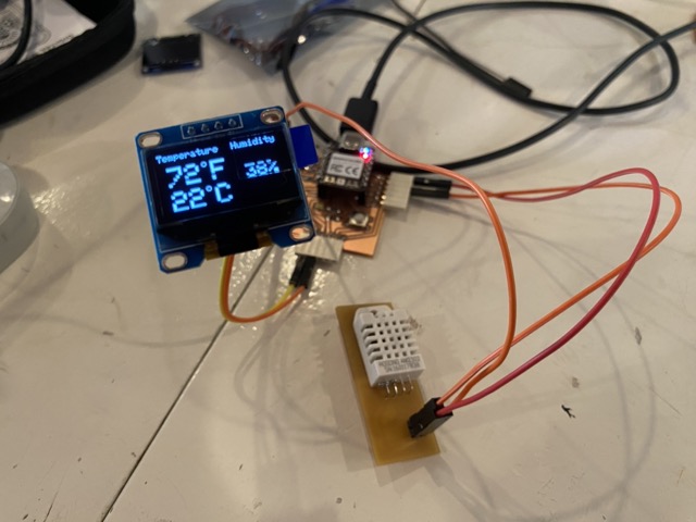
source code
//DHT sensor
#include "DHT.h"
#define DHT22Pin D10
#define DHTType DHT22
//#define FAN D6
//OLED
#include  <Wire.h>
#include <Adafruit_GFX.h>
#include <Adafruit_SSD1306.h>

DHT  HT(DHT22Pin,DHTType);
float humi;
float tempC;
float tempF;

//OLED  define
#define SCREEN_WIDTH 128 //OLED display width, in pixels
#define SCREEN_HEIGHT  64 //OLED display height, in pixels
//SSD1306 display connected  to I2C (SDA, SCL pins)
Adafruit_SSD1306 display(SCREEN_WIDTH, SCREEN_HEIGHT,  &Wire, -1);

void setup() {
  Serial.begin(9600);
  //For DHT11
  HT.begin();
  //pinMode(FAN, OUTPUT);
  //Necessary code for OLED I2C
  if(!display.begin(SSD1306_SWITCHCAPVCC, 0x3C))  { // Address 0x3D for 128x64
    Serial.println(F("SSD1306 allocation failed"));
    for(;;);
  }
  display.display(); //Displays the starting logo
  delay(1000);
  display.clearDisplay();
}

void loop() {
 delay(1000);
 humi =  HT.readHumidity();
 tempC = HT.readTemperature();
 tempF = HT.readTemperature(true);

 display.clearDisplay();
  oledDisplayHeader();
 //configures the position of the readings. (charactersize, x axis value, y axis value, reading, symbol)
oledDisplay(2,90,28,humi,"%");
 oledDisplay(3,-10,44,tempC,"C");
  oledDisplay(3,-10,16,tempF,"F");

 display.display();

}

void  oledDisplayHeader(){
  //configures position and qualities of headers
 display.setTextSize(1);
 display.setTextColor(WHITE);
  display.setCursor(0, 0);
 display.print("Temperature");
 display.setCursor(80,  0);
 display.print("Humidity");
}
void oledDisplay(int size, int x,int  y, float value, String unit){
 int charLen=18;
 int xo=x+charLen*3.2;
  int xunit=x+charLen*3.6;
 int xval = x;
 display.setTextSize(size);
 display.setTextColor(WHITE);

 if (unit=="%"){
   display.setCursor(x, y);
   display.print(value,0);
   display.print(unit);
 } else {
   if (value>99){
    xval=x;
   }  else {
    xval=x+charLen;
   }
   display.setCursor(xval, y);
   display.print(value,0);
   display.drawCircle(xo, y+2, 2, WHITE);  // print degree symbols
   display.setCursor(xunit,  y);
   display.print(unit);
 }

  }
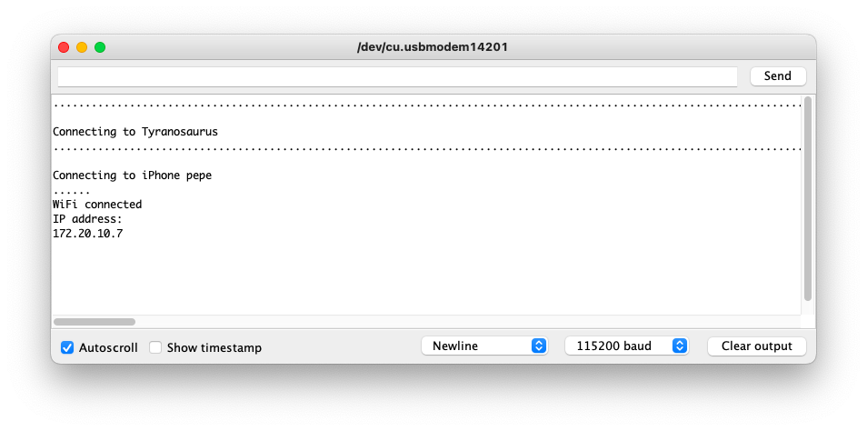
Connecting to Wifi
The xiao esp32 allows wifi networking either as an access point or connecing to a wifi network. For this I followed the tutorial here. For some unknown reason, I could not connect to the wifi in my house, but when I opened a Hotspot on my phone, it worked fine and connected.
The atena on the micro controllers are pretty strong, it picks up way more devices than i can find on my phone.

After failing with connecting to my wifi, I opened up a hotspot on my phone and it worked straight away.
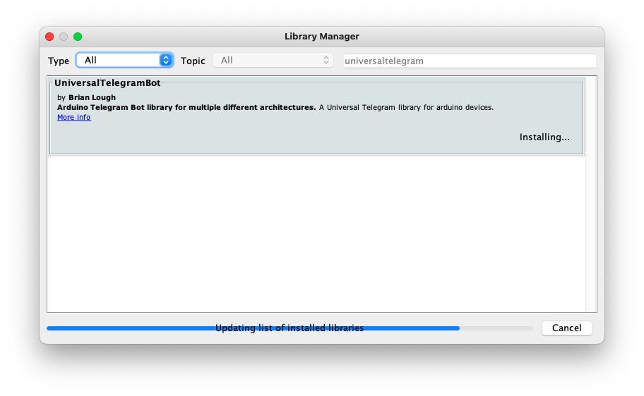
Connecting to Telegram
You can use a chat bot to control IO'S on the ESP, I have followed several tuturials, but so far I can't get it to work with my micro-controller. Following the steps, you set up a chatbot on telegram and that will give you a BOT Token, then you need your chat ID which you find on telegram with the help of an ID BOT. You then need to download the UniversaltelegramBOT libraries to your arduino IDE.
In the code you will set the local wifi address and password, the BOT Token and chat ID.
const char* ssid = "ADD_YOUR_SSID";
const char* password = "ADD_YOUR_PASS";
#define BOTtoken " XXXXXXXXXX:XXXXXXXXXXXXXXXXXXXXXXXXXXXXXXXXXXX"
#define CHAT_ID " XXXXXXXXXX"
So far this isn't working for me, I will continue to debug.
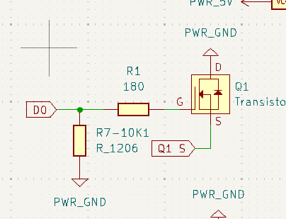
Mistakes
I think i tried to rush building the pcb and didnt take care of the electronics, I'm going to blaim a heavy head on monday after kings day. Good to know you've fucked up though I guess and where to put it right. So two major problems with my design, the fist one is the mosfet orientation. Inside the mosfet you can see the flow of electons is in one way like a diode and as the gate closes, drain to source can curcumvent that stop and you have the circuit connected. The way I have done it, the device will always be on as the load has a voltage and can pass through the mosfet to ground, so completly the wrong way around. The other failure was the tracks on the pcb, I have completley missed two ground points. So, third time lucky?
For the above reason, I wont be uploading design files until they are redrawn and working.
Class Notes
Connecting stuff
Star topology - main has 1:1 connections to all secondary
examples uart, spi
ring topology - chained together - addressing by place on the ring
bus topology connecting together examples i2c, wifi
Protocols
Asynchronous no clock data speed has to be set rx/tx with a fixed speed
UART - Universal Asynchronous Receive Transmit
SPI - Serial peripheral interface invented by motorola exchange date between main and secondary (miso-mosi) high data rate clock for data synchronization, use chip select(CS) to specify which receiver to talk to.
Examples - Flash Memory - SD cards - displays
I2C- IC communications invented by philips - 7 bit fixed address SCK - Serial clock SDA - Serial data GND
I/O expander, increases the amount of I/O's available by connecting all the SCK and SDA lines together and addressing the expander.
Bus pull-up/down - good practice to fix bus levels - spi 10kohm pull down - i2c 4.7kohm pull up