6. Embedded Programming

Learning outcomes
- Implement programming protocols.
Group assignment:
- Browse through the datasheet for your microcontroller
- Compare the performance and development workflows for other architectures
- Document your work to the group work page and reflect on your individual page what you learned
Research
So the board that we made in week 4 was a XIOA RP2040 32bit MCU, which means nothing to me, so asked chat gpt to give me a breakdown.
- MCU = Micro controller unit
- 32 Bit = The length of bits(0's or 1's) that can be processed at one time. Having chunks of 32 rather than 16 or 8, means more complex calculations can be made. This is due to the binary system, which again, need some explaining, but for now lets just say 32 = good!
- The Xioa part, I think that just means hello.
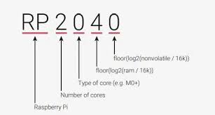
The data sheet also gives a little explanation of why its called an RP2040.
Compiler
A compiler is a software tool that translates source code written in a high-level programming language (like C++, Java, Python) into machine code (binary code) that can be understood and executed by the microcontroller or computer's processor. In the context of Arduino, the Arduino IDE uses a compiler to translate the sketches written in Arduino's simplified C/C++ language into machine code that can be executed by the microcontroller on the Arduino board.
Bootloader
A bootloader is a small program that is responsible for booting or starting up a larger program or operating system. In the context of micro controllers like those used in Arduino boards, a bootloader is a piece of software that facilitates the uploading of new firmware or sketches onto the micro controller's flash memory.
How to select Micro controller
- I/O ports
- other peripheries (adc,dac,spi,i2c,i2s,uart,timers)
- power consumption/speed
- environment
- cost(3 cent micro controller anyone?)
For our group assignment we split the group and worked through different IDE's to get our LED to blink.
IDE's
To write programs on the micro-controller, we use integrated development environments (IDE's), text editors ,or platforms that support the development of embedded systems. Here are some common tools and software options for programming an RP2040:
-
Arduino IDE: The Arduino IDE is a popular choice for programming microcontrollers, including the RP2040. You can add support for RP2040-based boards by installing the appropriate board definitions.
-
MicroPython: MicroPython is a lightweight implementation of Python 3 optimized to run on microcontrollers. RP2040 supports MicroPython, and you can write code directly in Python syntax.
-
CircuitPython: CircuitPython is a variant of MicroPython designed for use with Adafruit's line of microcontroller boards. RP2040 supports CircuitPython, and it provides a beginner-friendly approach to programming.
-
PlatformIO: PlatformIO is an open-source ecosystem for IoT development with support for many development platforms, frameworks, and boards, including RP2040-based boards.
-
Visual Studio Code: VS Code is a popular code editor with extensions that support embedded development. You can install extensions for specific microcontroller platforms, including RP2040.
-
Thonny: Thonny is a Python IDE that simplifies the process of writing, running, and debugging Python code. It supports MicroPython, making it suitable for programming RP2040 microcontrollers.
-
Official Raspberry Pi Pico SDK: If you prefer to work with C or C++, you can use the official Raspberry Pi Pico SDK, which provides libraries and tools for low-level programming of the RP2040 microcontroller.
For our group assignment we used VS, Micro-python and the arduino IDE's to blink LED's on the Quen Torres boards. Having previously downloaded arduino IDE, I have decided to continue with this environment.
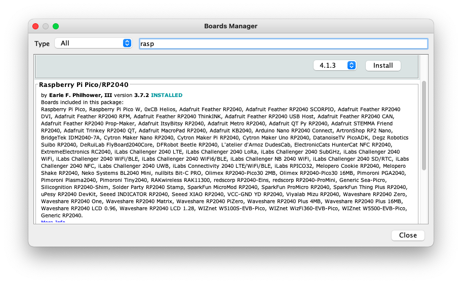
Board manager
To write programmes to the rp2040, you need to include the board settings in the IDE. To to that: open up the ide, go to tools and in the drop down select Board manager. You can then search for the board type, the rp2040 comes in a raspberry pico packages with many other board types.
Individual assignment:
- Write a program for a microcontroller development board to interact (with local input &/or output devices) and communicate (with remote wired or wireless devices)
Start with an idea
So this week I thought I could just spiral into creating a game with the Quen Torres Micro-controller built in week 04, where I copied and pasted some code into the Arduino IDE to make the LED blink. How hard could programming a game be, LOL.
Game :
- count the amount of LED blinks
- Use the button to enter the total amount of blinks
Idea could be that the levels to get incrementally harder as you play.
How levels get harder:
- Increasing the amount of blink
- Decreasing the blink duration
- Simultaneously LED blinks
- Decrease the input time-frame
Design rules:
- Random selection, the sequence should be varied enough that you cannot guess the sequence.
- Sequences should get increasing more difficult.
- A start action required, press the button once to start; Led's flash or maybe a three flash countdown to initiate the game.
- Once sequence is performed there is a time-frame for the input from the player.
- A subsequent pass or fail flash
- An end game/ await start command on fail
- Continue sequence with a pass


After some excellent and very high level code instructions from Erwin at the Waag, I was sent on my way to try and make sense of it all. In the end this was too big a spiral, so I decided to build on from week 4 and see what progress i could make.
Turning on/off 3 LEDs
From my previous weeks work, I was able to make all three LED's turn on together by defining their pins.
Code for 3 LED's on/off
#define LED1 D0
#define LED2 D6
#define LED3 D7
#define BTN D1


bool ledState = HIGH; // HIGH, true and 1 mean the same
bool btnState = HIGH; // button is high as it is connected to 3.3V via a pull-up resistor

void setup() {
  pinMode(LED1, OUTPUT);
  pinMode(LED2, OUTPUT);
  pinMode(LED3, OUTPUT);
  pinMode(BTN, INPUT);

  // set initial state of our LED
  digitalWrite(LED1, ledState);
  digitalWrite(LED2, ledState);
  digitalWrite(LED3, ledState);

}

void loop() {
  bool btnReading = digitalRead(BTN);

  // we want to do something only if the reading and the state are different
  // in this case they are the same and we exit the loop immediatly
  if(btnReading == btnState){
    return;
  }

  if(btnReading == LOW){ // LOW means button is pressed on Tarantino
    btnState = LOW;
    ledState = !ledState; // Flip led state by using negation operator
  }else{
    btnState = HIGH;
  }

  digitalWrite(LED1, ledState);
  digitalWrite(LED2, ledState);
  digitalWrite(LED3, ledState);
  delay(10);
}
Traffic lights
While looking around for code to steal, I found the Arduino Projecthub quite useful. I found some projects that are quite relatable to my final project with humidity and temperature programs. I also found a traffic light code that I sped up a bit and wrote to the controller for a test.
The next spiral
Blinking incrementally from button presses
I then moved on to try and blink one light after the other, for this I asked chat GPT. I copied and paste my previous code and asked it to change the code so that after each input; One input (or button pressed), would result in the first LED turning on and so on. It gave me some Code, but that didn't work. What was interesting in that code was a counting mechanism. I actually went back to the Arduino project page and was able to find a program that blinked incrementally, so i stole that code.
#define LED1 D0
#define LED2 D6
#define LED3 D7
#define BTN D1

const int buttonPin = D1;
const int ledPin[] = {D0, D6, D7}; // Array of LED pins
const int numLEDs = 3; // Number of LEDs in the sequence

int buttonState = 0;
int currentLED = 0; // Current LED to be illuminated

void setup() {
  for (int i = 0; i < numLEDs; i++) {
    pinMode(ledPin[i], OUTPUT); // Set LED pins as outputs
  }
  pinMode(buttonPin, INPUT); // Set button pin as input
}


void loop() {
  buttonState = digitalRead(buttonPin);

  if (buttonState == HIGH) {
    illuminateNextLED(); // If button is pressed, illuminate the next LED
    delay(250); // Debounce delay
  }
}

void illuminateNextLED() {
  digitalWrite(ledPin[currentLED], LOW); // Turn off current LED

  currentLED++; // Move to the next LED

  if (currentLED >= numLEDs) {
    currentLED = 0; // Wrap around if we reached the end of the LED sequence
  }

  digitalWrite(ledPin[currentLED], HIGH); // Turn on next LED
}
This was an important step, as I previously mentioned, I found a way to creates a count, something I would be reliant upon for the game to work. There was quite some work to piece together what I have found with next to no C++ experience, the code I was using for the LED's lighting incrementally, doesn't gel with the count code, but I needed to see if i could record a count. For this I used the Serial monitor In the Arduino IDE. To connect to the board go to: Tools and then...


For communication between the micro-controller and the Serial monitor a baud rate has to be set, this is the amount of bits per second are sent to and from the Micro-controller. You will also need to write the code in the setup.
void setup() {
  Serial.begin(9600);
  Serial1.begin(38400);
  Serial2.begin(19200);
  Serial3.begin(4800);

  Serial.println("Hello Computer");
  Serial1.println("Hello Serial 1");
  Serial2.println("Hello Serial 2");
  Serial3.println("Hello Serial 3");
I wrote my print statement in the loop, but it shows it's working at least.
So then I went on to test of my input would give the correct reading when I pressed the input button.
    if(btnReading == HIGH) { // Button pressed
      buttonPressCount++; // Increment button press count
      Serial.println(buttonPressCount++)**
For some reason this code gave me increments of 3 in the serial monitor. So I changed ++ to +1 on the serial.println.
    if(btnReading == HIGH) { // Button pressed
      buttonPressCount++; // Increment button press count
      Serial.println(buttonPressCount+1)
That seemed to work with the values going up by value of 1, but there was an issue with input not registering when button pressed.
I played around with the debounce delay value and found the problem got worse with a lower value, so I increased it from 50ms to 100ms and that seems to be working.
void loop() {
    bool btnReading = digitalRead(BTN);
   delay(100);// Debounce Delay
  // Check if the button state has changed
  if(btnReading != digitalRead(BTN)){
In the video I press 10 times from a start value of 90 and I end with 100.
Reflection
Spirals
Essentially i'm not a programmer, but I feel like there was some progress made in a short amount of time, I have a basis to go and find more code and I think I could eventually get the game to work. It has been an enjoyable week and I have made some sense of how I can get my final project to work, having found source for code that I can go on to use. As always, I am out of time, but there is an itch to scratch and a game to be made...
Have you answered these questions?
- Linked to the group assignment page [x]
- Programmed your board to interact and communicate [x]
- Described the programming process(es) you used [x]
- Included your source code [x]
- Included ‘hero shot(s)’ [x]