Week 9
Output Devices
Organizing
checklist
| group assignments | — |
|---|---|
| Measure the power consumption of an output device. | |
| Document your work on the group work page and reflect on your individual page what you learned. |
| individual assignments | — |
|---|---|
| Add an output device to a microcontroller board you’ve designed and program it to do something. |
This week I will look into motors and how to drive them, I also want to work with LED’s to see which one fits my final project best. I want to try to really focus on what I need for the final project and hit the brief of the assignment. And I would like to do something with an OLED screen.
| learning goals | — |
|---|---|
| — | check out the neopixel: 8213 8212 WS R+G+B+W |
| connect a small motor for the final project | |
| work on the gears mechanism for the final project | |
| try out an OLED screen | |
| — | design a new (sub)board related to the final project |
| — | think about what I’m going to make in the moulding and casting week and with which material. |
General notes on output devices.
For the following information I combined information from Neil’s lecture and Thursday’s workshop at Waag from Henk, Michelle en Leo.
Power output devices
Electrical safety human body 1 mA you won’t feel it 10mA you will get a chock 100Ma hart attack If you work around big capacitors, hold something thats insulated.
USB Power
- can be used when you are dealing with higher power output devices like power LED’s for example.
USB QC
- much easier to implement example: Nicolas de Coster
batteries
- Limos modules to manege the charging.
- Watch out they are a fire hazard.
- The Xiao Esp32c3 has an integrated charger, look into this!
Measure loads
- You need to measure loads to characterize the output device!
- You need to know the power draw of for example the motor to know with battery you need to use.
- You can do this by putting a tiny resister (1 Ohm) to the ground in the circuit and measure the voltage across that.
PWM
- One of the most important concept for this week topic is PWM (pulse width modulation)
- Use this to switch loads, makes pulses and varies the fraction of on and off pulse this is called duty cycle
- For example to dim a LED very the durations of on of and the periods of time between
- it’s in time but define the time of the microcontroller by bits
- with 8 bits, it has 255 value’s
LED’s
- blue and green use the most forward Voltages
- Neopixel uberguide - adafruit
- watch out NEOpixels use a lot of memory, every pixel needs memory to calculate the light color, brightness etc.
- Charlieplexing: array of LED’s, cathodes in a row, anodes in a colum
- A pin can be on, of or disconnected (input) you can program at the LED’s easily this way without many tracks.
- Super bright LED’s that pull 150 mA current for example need MOSFET’s because a processor pin from a micro controller can only do around 20 mA. Bright LED’s can burn your eyes and have a temperature issue, because they can get hot. This can be fixed with MOSFET’S
- There is an example board for PWM LED’s bright ones on the T412
- LED’s have a diode drop of 2 volt (typical value) If the diode drop adds up to your power supply you don’t need a resistor anymore.
- Making multiple strings in parallel. 3 strings in this example. At the bottom the N MOSFET is placed.
Neopixel
- digital RGB
- doesnt use the pin’s forward voltages but uses an external forward voltage
MOSFETS
- Two types N mosfet - P mosfet
- Both have a gate to control it. Is has a source and a drain Drain -> load Source -> supply
- There is a bigger resistor to keep the MOSFET of unless you choose to turn it on.
- The other resistor is a small resistor to slow down the transition so it’s not as noisy
Displays
LCD’s, don’t recommend anymore because of newer ones, if you put power on the pixel it turns black.
OLED, 128 by 64 pixels, hello world tests board ans code examples of the Fabacademy website.
Neil uses MicroPython for this.
SSD1306 is a common chip to drive these OLED displays. Use the library and use I2C data communication module. This consist of two pins, SCL and SDA pins, one is a clock pin and the other a data pin. And you need a pull-up resistors, typically they are on breakout boards already, around 10KOhm.
if you order one make sure you match the driver and library So OLED SSD1306, needs 1306 library and driver
double check the pins, which is ground, power etc.
TFT,
SPI communication instead of I2C
ILI93 and Uglcib library common chip and library to work with this display
E-ink, big advantage of this display is that it retains the image when you turn the power of.
H-bridge with motors
- TB67H451AFNG,EL is a typical motor driver making it able to turning a motor in both directions.
- It consists of two circuits in the shape of a H.
- It receives a low voltage and pumps it up to a bigger one. It has sensors and PWM.
- You can ude this H-bridge up to 3.5 amps and 44 V!
- Sample board with a RP2040 Xiao. On the board you need bigger traces (with lots of currents) use a trace width calculator.
- The thermo pad underneath in the example is for the heat.
- The example uses two extra capacitors. A small one for smaller spikes and the bigger one for providing current for the H bridge. Use them!!! your motor will be more reliable
- Note : arduino calls PWM: analog write
- Efficiency v.s. RPM if you want the motor to run slowly use a gear head motor
- Motor with unbalanced weight it becomes a vibrating motor
H-bridge with audio
- Speakers, if you connect a H bridge and PWM you can produce audio with the same sample Xiao board with a H bridge for driving motors.
- Musical notes corresponds to a wave form and when you very the frequency of the wave form, loop the music notes and loop the pitches the pitches come from a table (sign wave) you can play notes with PWM.
- PIO - little processors around the main one. they run tiny program’s very fast!
- DFplayer - module to play mp3 files! I think I will use this if I want to do something with audio.
speakers
- Piezo, reacts on movements so when it detects movements if can put out signals, or the other way around.
- Speakers are made with a coil inside
Motor types
Servo motors
- location control via PWM
- you can buy 180 degrees one or a 360 degreed one but mostly you need the 180 degrees.
- Control the angle of the servo
- Easy to work with be ware they run on 5V
- Depending on the size of the servo you need a external supply.
DC motor
- use physical brushes, can be noisy
- direction of the motion is the direction of the current
- varying the speed with a potentiometer but it’s mostly on and of and ons turns fast
BLDC (brush less DC motor)
more silent and electrically efficient.
It has 3 brushed and half bridges. you turn the three of them on and off to control the motor.
You have many different kinds of (BL)DC Motors: inrunner, outrunner(low RMP, like drones), pancake (flat) fan, gimbal (to control the angles)
Ams and Dollars are roughly connected when you look at costs.
most common used controllers for them is ESC (electronic speeds controllers)
Stepper motors
- Moving slow and fast forwards and backwards really precise
- You can find them in your 3D pinter
- Accel Step library, accelerating of setting stepper motors
- It has two sets of coils with 2 H-bridges. There circuits are interleaved and it has two sets with magnets.
- You can turn them 1.8 degrees, this is typical to align the magnet to the coils..
- DRV8428, typical controller chip to send a signal to say which directions you want the motor to go to and it does micro stepping, you can vary the current to the coils to achieve 250 micro steps!
- flat stepper motor the motor is a linear ray of magnets
- one is the power and one is the V-power
- Arduino library, setTargetPosition
- StepStick, for driving the stepper
Solenoid
- coil of copper for moving up and down
- attracts bits of metal
- if you run current through the coil it becomes magneticTip: Look at artificial muscles, memory wire and inflatable muscles for organic movements and soft/ quiet movements.
Group assignment
Measure power consumption of an output device
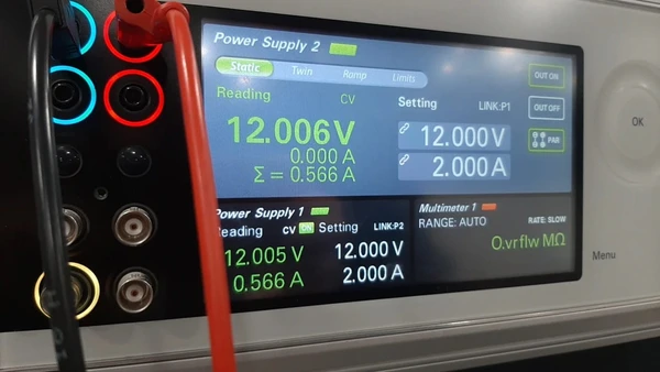
- easiest way is with a power station Fablab Waag has two of them.
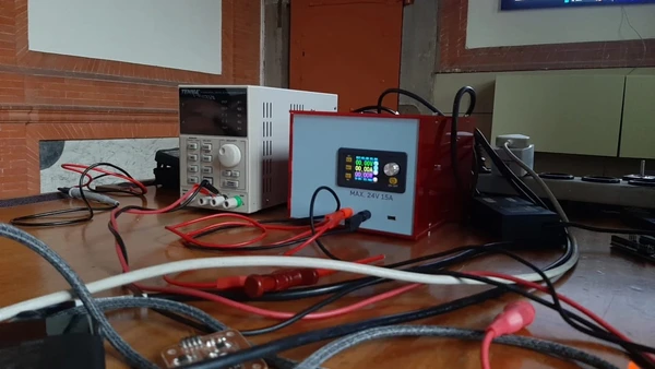 First power supply(left side of the pic)
Set the voltage and current in the power supply: Voltage - 5.0 This is set to the Voltage the output device needs, look it up in the datasheet Amps - 0.5 This to a current that you know will provide enough for you output device, it won’t drive more current than it needs so you can have to little current but you can’t drive to much current.
The power station has three cables:
- Black : minus
- Red : power
- Green : earth (generally we don’t use this one)
Measuring an Arduino:
- How do you change the voltage:click on voltage and change the button to change the voltage
- USB is 5 volt so for the arduino we use 5V
- Always first connect the ground to prevent a floating ground especially with micro controllers!!
- connect the power
- two on/of buttons one for the power station and one for the circuit. Put on the circuit and observe.
- calculate the power consuming using the following formula:
voltage * current = power.
- The power consumption of the output can be for example 5 Watts there is no time in Watts.
- Batteries will give you watts or amps per hour, so there is a factor times in the battery MaH milliamps timer hour how much is consumes in one hour.
- wH Watts hour
- MaH milliAmps times hour
- Is it a power consumption over time or is it the power.
The arduino draws:
- 0.5 V
- 0.02 A
- 0.09 W
Power drop: (voltage drop)
- if you power a device it pulls a lot of amps and then you see a short voltage drop
- the arduino needs a minimum amount of volts to power it
- the micro controller will restart because when you turn on the motor the voltage drops and the micro controller stops, start things gradually helps prevent this problem and adding capacitor does too.
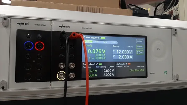
Second Power supply (Dc- DC) (right side of the pic)
- you can connect in to your PC to see what’s happening
- it calculates Watts for you already
- to set the v and amps click the buttons and turn the big knob, you see the settings in the upper part of the screen
The small DC motor I brought today to test:
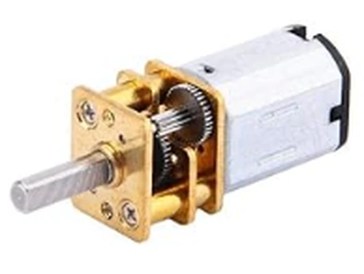
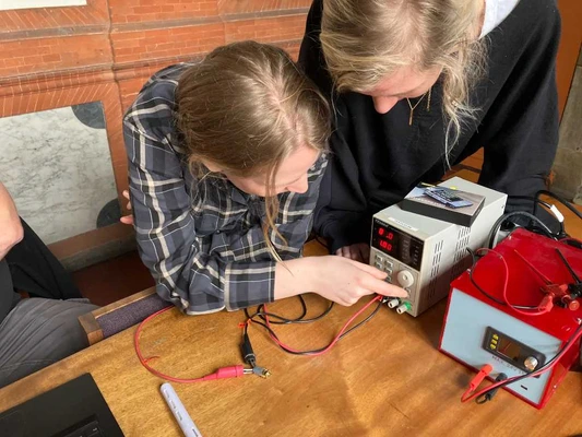
Since I don’t know how much volt it draws I don’t know how to set the V on the power supply. On the internet you can find different Voltages so we start low with 3V and bring it up to see when it will turn. It uses 5V.
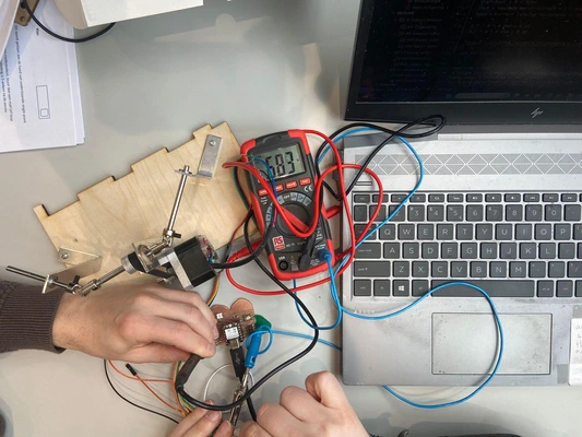
In this picture from Leo you can see Joany and me working with it.
Power consumption:
- 5V (0.005mV)
- 43 mA
- 0.22 mW
Stepper motor
Leo, Joany, Joe and I used the Step stick driver together with my breakout board designed for the ESP32C3 Xiao and the 17HS19-2004S1 stepper motor to test the steppermotor together. Leo documented the set-up wiring and VRef fixing of our board and driver and the hardware troubleshooting I documented the coding below:
Some important notes of things I learned:
- Capacitors are to big to place inside of a IC, thats why you need to add them.
- Stripes above pin names in datasheet indicate that the value is standard HIGH instead of LOW.
- define function doesn’t need the ; at the end of the code line.
- Together we wrote the first code to test if the motor will do anything. Leo’s explanations of the code are super helpful and I tried to sum them up in the explanation lines in the code.
#define DIR D9 // creates a new name for pin D9
#define STEP D10 // creates a new name for pin D10
int speed = 20; // creates a integer (whole number) to store the speed value.


void setup() {

  pinMode(DIR,OUTPUT); // sets DIR(pinD9) to an output pin
  pinMode(STEP,OUTPUT); // sets STEP(pinD10) to an output pin
  digitalWrite(DIR,true); // sets the pin to true meaning high meaning 1
  // put your setup code here, to run once:

}

void loop() {
  digitalWrite(STEP,HIGH); // creates on step
  delay(speed); // waits
  digitalWrite(STEP,LOW); //stops step
  delay(speed); // waits
  // put your main code here, to run repeatedly:
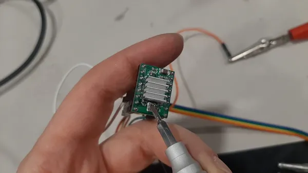
}- We run into troubles with the circuit of the stepper motor. We switch A an B on the step stick and finally changed the VRef we measured it with a multimeter set to the potentiometer and ground and changed it to 0.5V, 1A this fixed our problems. We measured the power consumption of the stepper motor: 2.88W.
Once we’ve got the motor doing steps we continue with adding code to make it go both directions and to do micro stepping.
#define DIR D9
#define STEP D10

int speed = 100;
bool direction = false; //create a boolean (false or true) for the direction
int degrees = 90; // create an integer to store the degrees
int microstepresolution = 32; // create an integer to store the micro stepping resolution in this case we went for the smallest steps setting Mode0 Mode1 and Mode2 to high meaning it takes one step of 1.8 degreed and divides it by 32 as you can see in the voidloop

void setup() {

  pinMode(DIR,OUTPUT);
  pinMode(STEP,OUTPUT);
  digitalWrite(DIR,direction); // sets the direction

}

void loop() {
  int amountofsteps = round((degrees/1.8)*microstepresolution); // calculates how many microsteps you need to turn to a certain amount of degrees.
  for (int i = 0; i <amountofsteps; i++) { // keeps adding one step until the amountofsteps is reached
  digitalWrite(STEP,HIGH); // makes on step
  delayMicroseconds(speed); // speed of turning
  digitalWrite(STEP,LOW); // stops step
  delayMicroseconds(speed); //speed of turning
  }
  direction = !direction; // this variable stores the direction and changes it.
  digitalWrite(DIR,direction);
  delay(1000);

}- The fastest I could make the stepper turn with the code above was an int speed of around 10 if you make the number smaller it doesn’t turn anymore. As a last step we altered the code to make it go 10 turns by multiplying the degrees:
#define DIR D9
#define STEP D10

int speed = 20;
bool direction = false;
int degrees = 10*360;
int microstepresolution = 32;

void setup() {

  pinMode(DIR,OUTPUT);
  pinMode(STEP,OUTPUT);
  digitalWrite(DIR,direction);
  // put your setup code here, to run once:

}

void loop() {
  int amountofsteps = round((degrees/1.8)*microstepresolution);
  for (int i = 0; i <amountofsteps; i++) {
  digitalWrite(STEP,HIGH);
  delayMicroseconds(speed);
  digitalWrite(STEP,LOW);
  delayMicroseconds(speed);
  }
  delay(1000);


  // put your main code here, to run repeatedly:

}
You can find video’s of the turning stepper motor on Leo’s page
Individual assignments
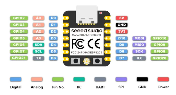
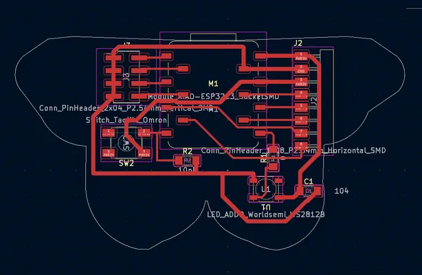
This week I want to focus on output devices I need fot the final project so I start with the gear mechanism and the motor. I will work with the ESP32-C3 Xiao based break out board I designed in week 8.
Mini micro gear DC motor
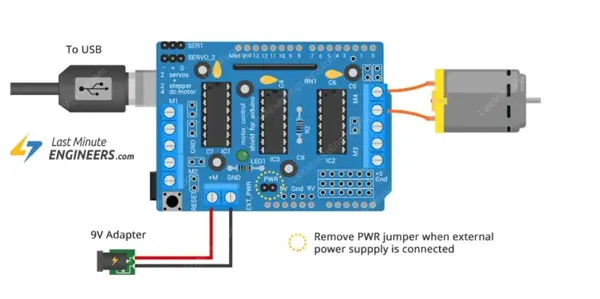
In the weekend I start with trying to get a Micro Metal Gear Motor to move. Henk gave me this L293D motor driver shield to power it and I found this tutorial to connect a DC motor, I follow the tutorial until I found out my driver does not have a USB insert. Update: I know now that there should be an arduino attached to it and it only fist one way. All the pins align so it’s really easy to fasten it. We used it for our group assignment first version on the robotcar and connected 4 DC motors for the wheels.
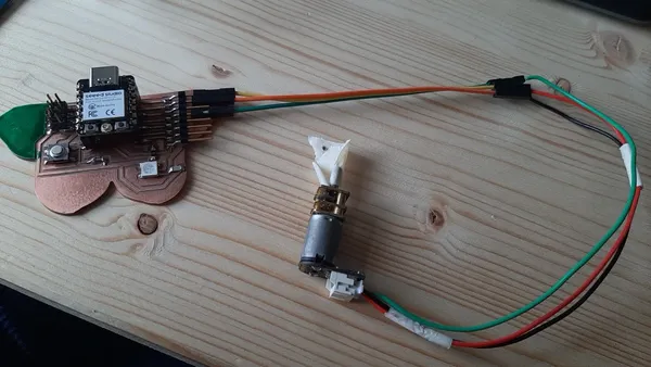
 I look up more tutorials.I can’t find one without a USB cable with the same shield that I can follow. I found this on very helpful to learn about programming a DC motor with a shield but I can’t find the pins she uses on the shield I got. She uses a different one. I give up for now and use the DFR0429DFROBOT instead this is a micro metal gear motor with a driver on the back of the motor, it’s a bit more expensive but we had it laying around in the lab. It works on 5V with 40mA.
I follow this tutorial to power it and program it and I run into an update status stating all the micro controller the library is designed for and it’s missing the ESP32.
I look up more tutorials.I can’t find one without a USB cable with the same shield that I can follow. I found this on very helpful to learn about programming a DC motor with a shield but I can’t find the pins she uses on the shield I got. She uses a different one. I give up for now and use the DFR0429DFROBOT instead this is a micro metal gear motor with a driver on the back of the motor, it’s a bit more expensive but we had it laying around in the lab. It works on 5V with 40mA.
I follow this tutorial to power it and program it and I run into an update status stating all the micro controller the library is designed for and it’s missing the ESP32.
#include <ESP32Servo.h>

#define speed_maxP 0   //Clockwise rotation (Max speed)
#define speed_maxN 180 //Anticlockwise rotation (Max speed)
#define speed_stop  90 //Stop

Servo  mymotor;  // create servo object to control a servo (my motor)
                 // twelve servo objects can be created on most boards

int pos=0;
void setup()
{
  mymotor.attach(D10);  //attaches the motor on pin 9 to the servo object
}
void loop()
{
  /**********Using 180 degree servo library to control N20 motor******************************/
  mymotor.write(speed_stop);     //Stop
  delay(1000);                   //delay 1s
  mymotor.write(speed_maxP);     //Clockwise rotation
  delay(2000);                   //delay 2s
  mymotor.write(speed_maxN);     //Anticlockwise rotation
  delay(2000);                   //delay 2s
  for(pos=speed_maxP;pos<speed_maxN;pos++)  //slow down, change the direction and speed up
  {
    mymotor.write(pos);
    delay(2000);
  }
}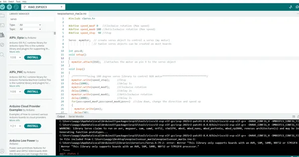
I download this ESP servo library instead and then the motor starts turning and alter the following code: #include <Servo.h> to: #include <ESP32Servo.h> and the motor started turning. I try to alter the speed because it’s moving really fast. But everything I adjust seems to have 0 effect on the motor I also find the motor very noisy. I leave it how it is for now and want to check out what’s wrong later.
Stepper motor
I redesigned the gear mechanism to get more surface for the teeth and I want to make smaller gears to make it less robust. I follow this tutorial to create new beveled gears and it took me a bit more time then anticipated.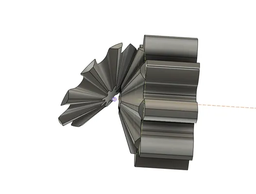
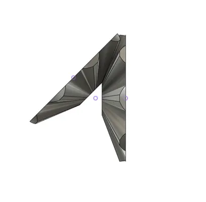 When They are finished I try to past them into the design for the lamp but I get stuck in how to make the rotating part because it has so little space left for making pillars for it to stand on.
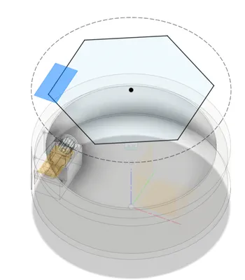 At monday I discussed with my college and after a while decide to go another route and used these moving mechanism parts called universal coupling instead. They should be able to turn in an angle of max 45 degrees. And we have a few of them laying around so I can test something right away because my goal is to put a motor to the mechanism and letting it move with a driving belt.
I spend the morning in the metal workshop cutting plates, punching holes, bending drilling and using the lath to make the shaft 4 mm on both ends for the universal couplings and 5 mm in the middle for the pulley to drive the belt. 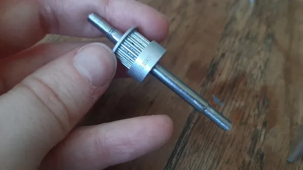
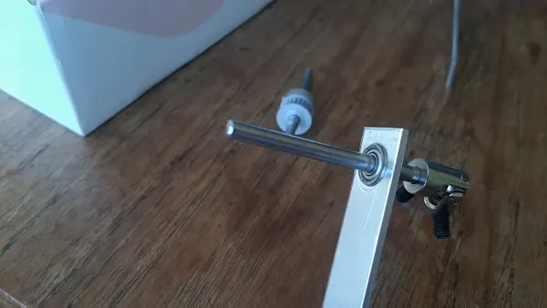 I had two pulleys laying around from an old 3D printer and I found an old stepper motor to.
I test the mechanism with my hands and it works nice.
Want it to work with the motor now. I have found the following parts laying around: A4988 pululu stepstick steppermotor driver Nema 17 stappen motor 42BYGHW609 Wantai
And I start by connecting the stepper motor to the stepstick following this schematic
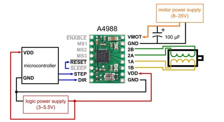
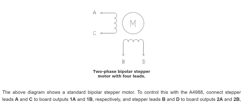
I have the following schematic to help me wire the two coils correctly. (still managed to do it wrong..)
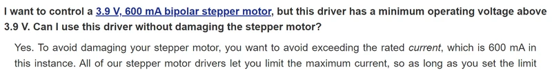
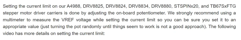
had no succes so I know I have to check the VRef for limiting the current because it can make your motor act weird if it’s set wrongly. And up a whole afternoon changing the VRef to make this motor do something but I just can’t get it wright.. I put the Powersupply on 12 V and 2 Amps, in the text below I read to not go below 0.60 amps so that should be right and in the data sheet of the motor I see it’s operating current is between 8 and 30 V.
I used the following video to make sure I do it wright vref currents limit
And used the formula to calculate the Vref:
Vref=Imot x 8 x Rsen
Imot = maximum motor current = 1.7 Amps in the datas sheet
Rsen = current sensing resistance = driver datasheet 0.050 ohms before 2017 0.068 ohms after
1.7 * 8 * 0.068 = 0.92
1.7 * 8 * 0.050 = 0.68
Since I don’t know if the driver is older or younger than 2017 I used both to check what works.
 The motor makes a sound but no success in moving.
I enter a rabbit hole of the VRef convincing myself this should be the issue.
Ignoring this message :
The motor makes a sound but no success in moving.
I enter a rabbit hole of the VRef convincing myself this should be the issue.
Ignoring this message :
And going for the trial error approach got me to this:
But you can hear the motor is unhappy so something else is wrong and I don’t know yet what. For this I used the full step mode and the following code:
#define DIR D9 // creates a new name for pin D9
#define STEP D10 // creates a new name for pin D10
int speed = 20; // creates a integer (whole number) to store the speed value.


void setup() {

  pinMode(DIR,OUTPUT); // sets DIR(pinD9) to an output pin
  pinMode(STEP,OUTPUT); // sets STEP(pinD10) to an output pin
  digitalWrite(DIR,true); // sets the pin to true meaning high meaning 1
  // put your setup code here, to run once:

}

void loop() {
  digitalWrite(STEP,HIGH); // creates on step
  delay(speed); // waits
  digitalWrite(STEP,LOW); //stops step
  delay(speed); // waits
  // put your main code here, to run repeatedly:

}
I changed the driver to another one of the same brand. Same problem so something else is wrong. I will now try to change the stepper motor for a different one to see if it fixes the problem.
Update:
I have found the problems of why my stepper motor was not working correctly. I had to one by one exclude things that could be wrong. So starting with the motor. A college tells me the motor should be able to spin when not connected and mine is very hard to spin, it’s stuck. This already explains a lot about why the motor is making this noise and why it’s not moving correctly. I’m going to switch the motor for a SY42STH38-1684A stepper motor from an old Ultimaker. The motor is not working so I decide to switch everything, so new cables new set-up using a breadboard double checking everything, new code and new microcontroller. I had everything set up but no success.. Only one item left to switch the driver. My college Niels has a different driver with the same pin schematic we put it in place and the motor starts turning! Finally. I switch things back, using my own micro controller and my own code. It all works well. Although the code using the library if working way more smooth then the code we made during the group assignment.
This is the code I used I downloaded the StepperDriver library for it and from this library I used the example: basic stepper driver. I only changed the DIR and STEP pinouts.
/*
 * Simple demo, should work with any driver board
 *
 * Connect STEP, DIR as indicated
 *
 * Copyright (C)2015-2017 Laurentiu Badea
 *
 * This file may be redistributed under the terms of the MIT license.
 * A copy of this license has been included with this distribution in the file LICENSE.
 */
#include <Arduino.h>
#include "BasicStepperDriver.h"

// Motor steps per revolution. Most steppers are 200 steps or 1.8 degrees/step
#define MOTOR_STEPS 200
#define RPM 120

// Since microstepping is set externally, make sure this matches the selected mode
// If it doesn't, the motor will move at a different RPM than chosen
// 1=full step, 2=half step etc.
#define MICROSTEPS 1

// All the wires needed for full functionality
#define DIR D9
#define STEP D10
//Uncomment line to use enable/disable functionality
//#define SLEEP 13

// 2-wire basic config, microstepping is hardwired on the driver
BasicStepperDriver stepper(MOTOR_STEPS, DIR, STEP);

//Uncomment line to use enable/disable functionality
//BasicStepperDriver stepper(MOTOR_STEPS, DIR, STEP, SLEEP);

void setup() {
    stepper.begin(RPM, MICROSTEPS);
    // if using enable/disable on ENABLE pin (active LOW) instead of SLEEP uncomment next line
    // stepper.setEnableActiveState(LOW);
}

void loop() {

    // energize coils - the motor will hold position
    // stepper.enable();

    /*
     * Moving motor one full revolution using the degree notation
     */
    stepper.rotate(360);

    /*
     * Moving motor to original position using steps
     */
    stepper.move(-MOTOR_STEPS*MICROSTEPS);

    // pause and allow the motor to be moved by hand
    // stepper.disable();

    delay(5000);
}
Here you can see the stepper motor working on my board!
It draws around 0.6 amps
OLED screen
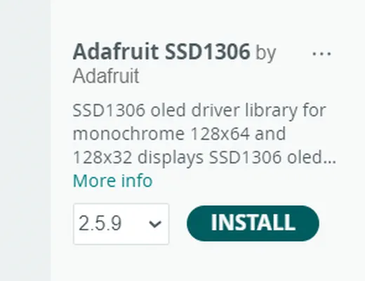
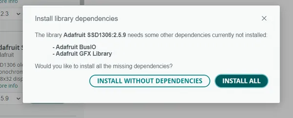
I follow this tutorial about working with the OLED screen and the ESP32 chip. I installed al the librarys
I wire up the display to my breakout board and make sure I connect the GND, VCC, SCL and SDA correctly I use the 3.3V VCC power supply. I use the following code and it work perfect right away.
#include <Wire.h>
#include <Adafruit_GFX.h>
#include <Adafruit_SSD1306.h>

#define OLED_ADDR   0x3C
Adafruit_SSD1306 display(128, 64, &Wire, -1);

void setup() {
  display.begin(SSD1306_SWITCHCAPVCC, OLED_ADDR);
  display.clearDisplay();
  display.setTextColor(WHITE);
  display.setTextSize(2);
  display.setCursor(20, 20);
  display.println("Hello world");
  display.display();
}

void loop() {}
I quickly looked at [this] tutorial for getting to make my own design. and I added a square stripe and a circle and some more text. Looked up how to do things with images and run out of time and left it there for now.
(https://randomnerdtutorials.com/guide-for-oled-display-with-arduino/)
](Schermafbeelding%202024-03-26%20210311week9.webp)
Reflection
This week was a messy week, I run in to more problems than I hoped. It made me understand how much I still have to learn on this subject. It’s hard for me to figure out whats wrong and everything took so much time! However I’m glad I made the turning mechanics and I got to try out 4 different power supply’s a device I never used before so I’m learning a lot of new things. I hope to get more knowledge on the subject the coming weeks and make a better version of this week for my final project. I also still want to test different kind of Neopixels to see which one is best for my nightlight. I was able to use my buterfly breakout board that I created in week 8 for everything this week!