System integration
Topic(s) of this week
- system integration
Hero shots
Assignments
Individual assignment
- Design and document the system integration for your final project
What I think I already know
This week is all about system integration. So how to combine all subsystems and subassemblies into one nicely integrated final project. From the start of my designs I took the integration into account. For example when designing the fixtures, I took into account to add space for the wires to go into.
As it happens, most of my subassemblies are done, so I can not oly think about system integration this week, but I can actually immediately do it.
SSTM planning
Supply
| Day | Supply | Tasks |
|---|---|---|
| Thursday | 08:00-15:30 | friction welding and lasercutting PLA sheet |
| Friday | 9:00-13:00 (fablab) | bending PLA sheet |
| various FP work | ||
| Saturday | 15:00-17:00 | Create and test first cable harness |
| Sunday | 20:00-23:00 | Create cable harness |
| Monday | 10:00-11:00 | Create cable harness |
| 19:00-22:00 | programming FP | |
| Tuesday | 9:00-17:30 (fablab) | solder connectors to sensors |
| finish wiring harness | ||
| lasercut and glue new UI fixture | ||
| 20:00-01:00 | programming FP | |
| Wednesday | 9:00-12:00 (fablab) | programming FP |
| documentation | ||
| 12:00-13:00 | Local review | |
| 13:00-14:00 | Regional review | |
| 15:00-18:00 | Neil time |
Tasks
- Leave feedback in Nueval that this weekly is ready for evaluation.
Individual assignment
All progress on integrating the subassemblies into my final project is documented in the final project documentation. Few interesting things happened this week, so I’m documenting those here.
My final project has several parts:
- Mechanical: all fixtures that hold different elements, the back plate and the cover sheet
- Electronics: Main PCB, 4 sensor PCBs, UI PCB, cable harnesses
- Pressure sensors: documented separately because this is the main thing that makes my final project work.
- Programming: the firmware for the main microcontroller (SAMD21E) and the sensor microcontrollers (SAMD21J)
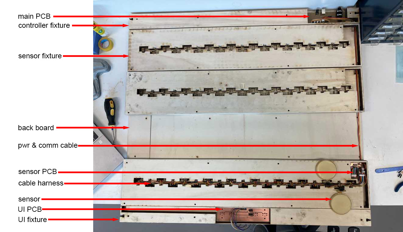
The way these parts integrate is shown in the image below (which shows the backside of the Marimbatron):
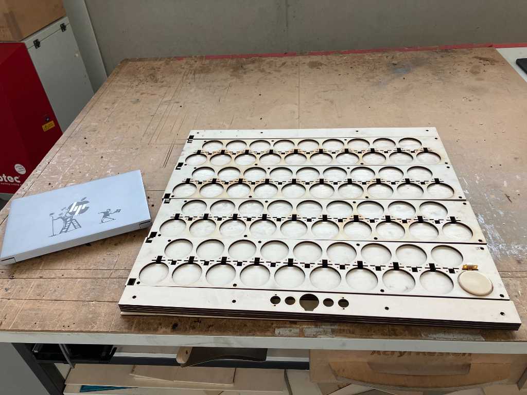
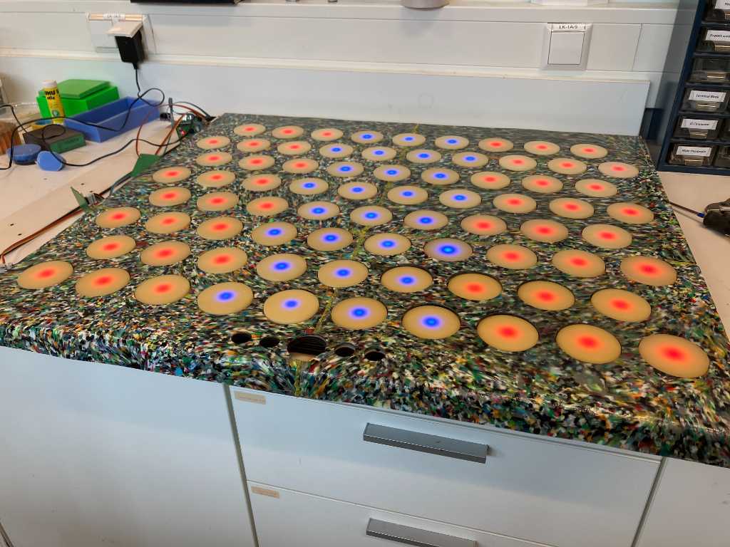
The front looks like this:
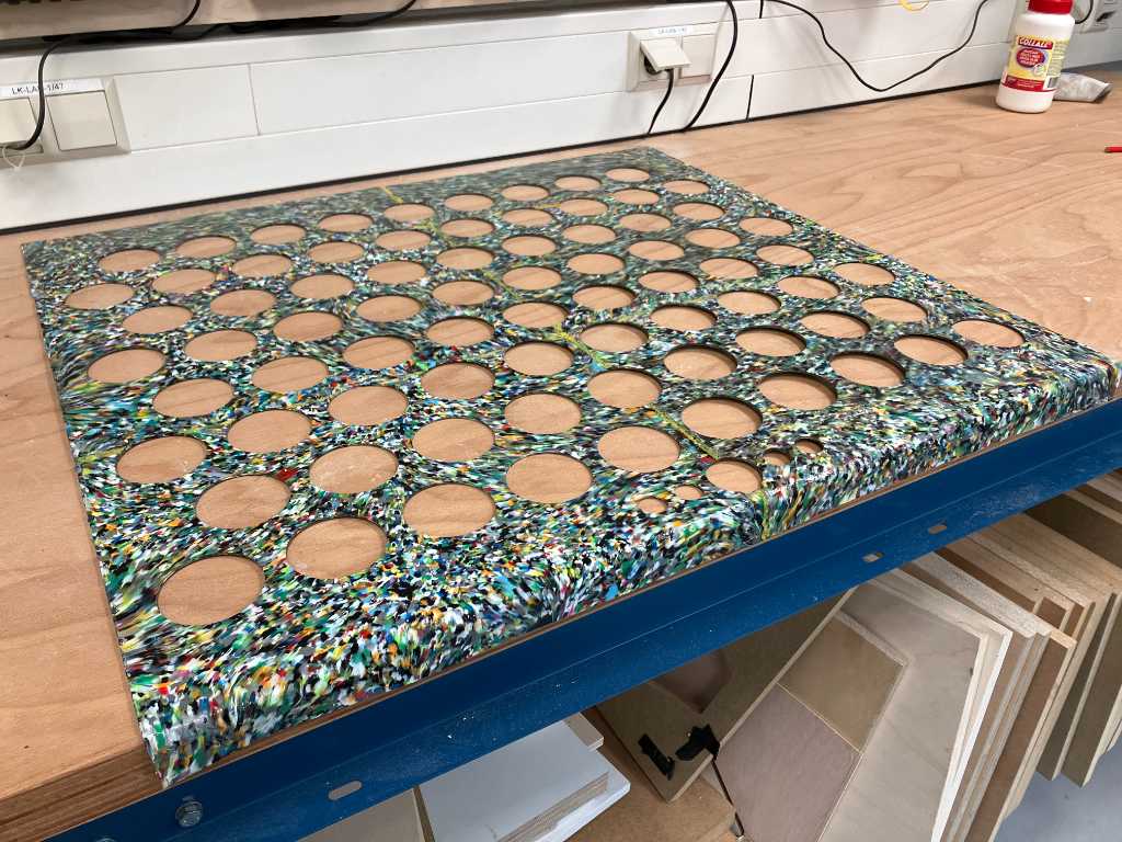
with this sheet that goes on top:
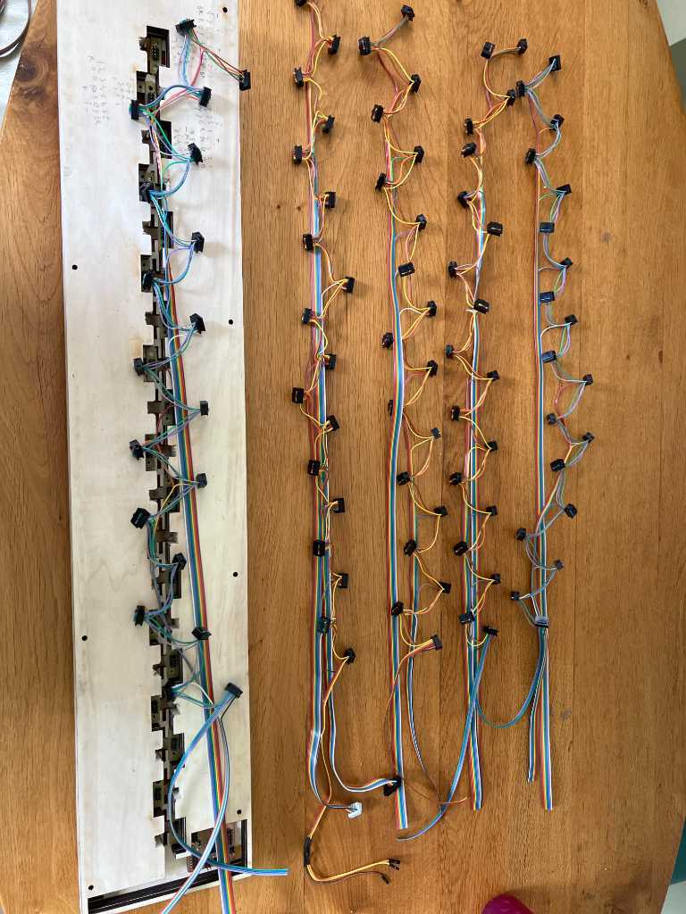
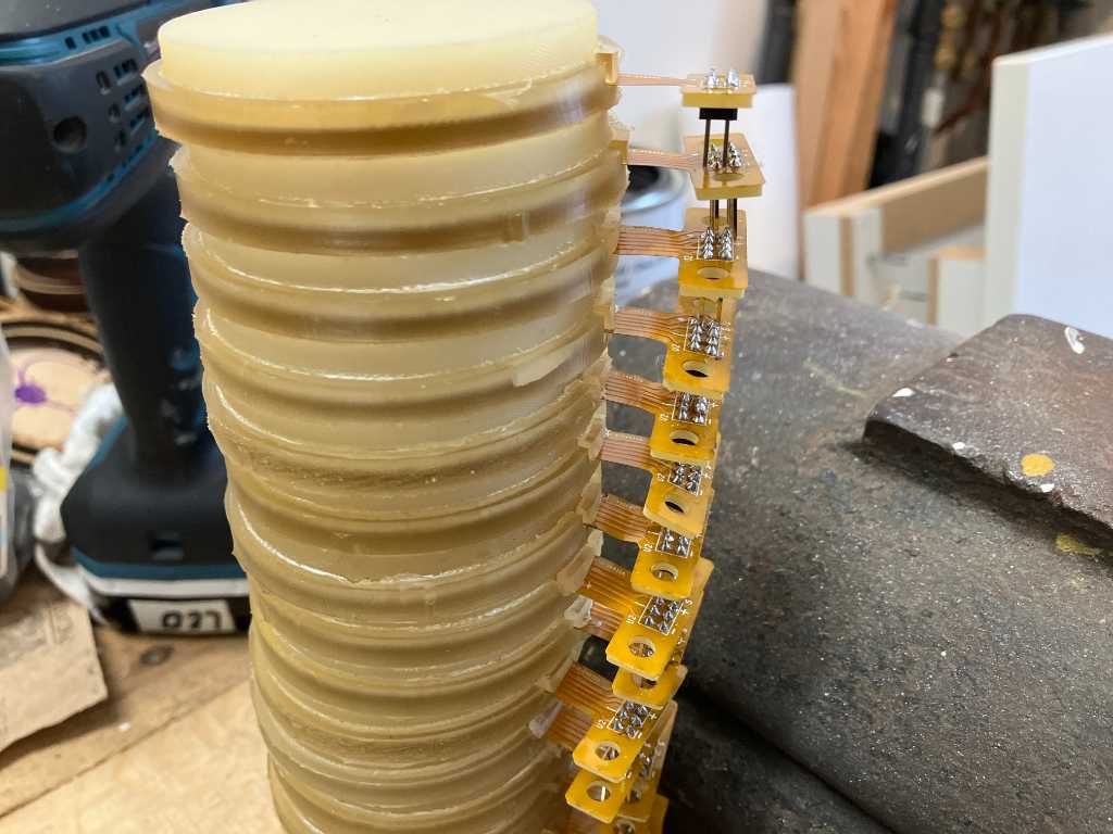
Over the last couple of weeks I made all the subsystems and tested them individually.
This week I focussed on putting them together and connecting them together with cable harnesses:
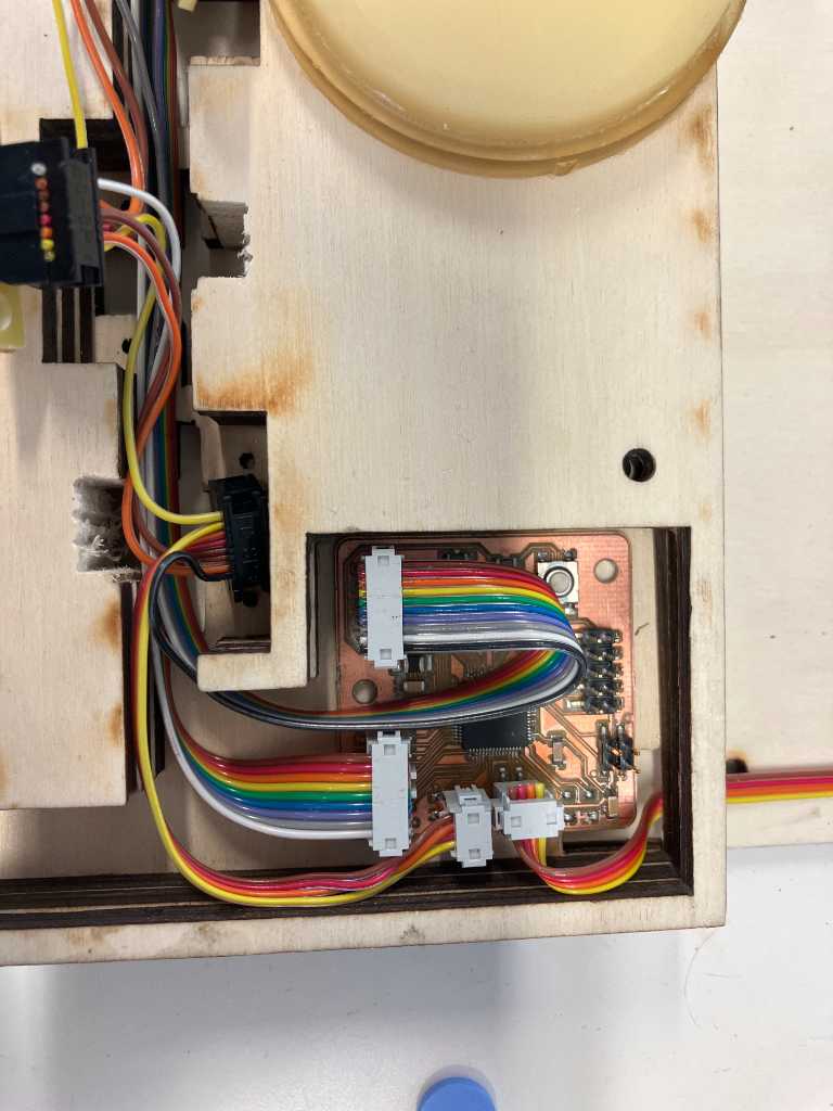
I had 2 serious issues that had to be solved. The sensors were the wrong side up and the voltage regulators became too hot.
Sensors wrong side up
Somehow I made a mistake in my design (although I tested a lot, apparently not enough). When putting the sensors in the sensor fixture, they are upside down. And due to the design, they don’t fit in the other way up. Also I can’t reach the inside of the cable harness cavity in such a way that I can do proper cabling. So I need to change the connectors and the sensor fixtures.
The only way the connector can go in:

Makes that the sensor is upside down:
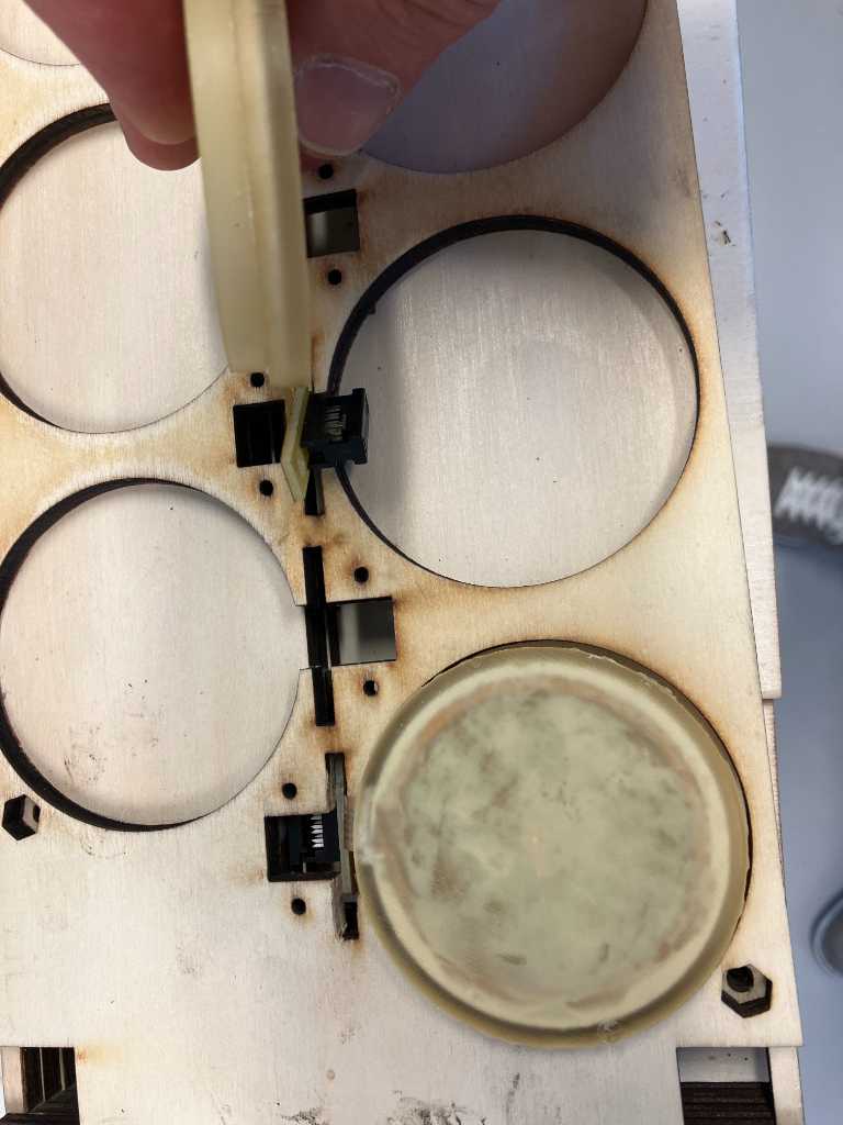
So had to manually make space:

So that they fit correctly:
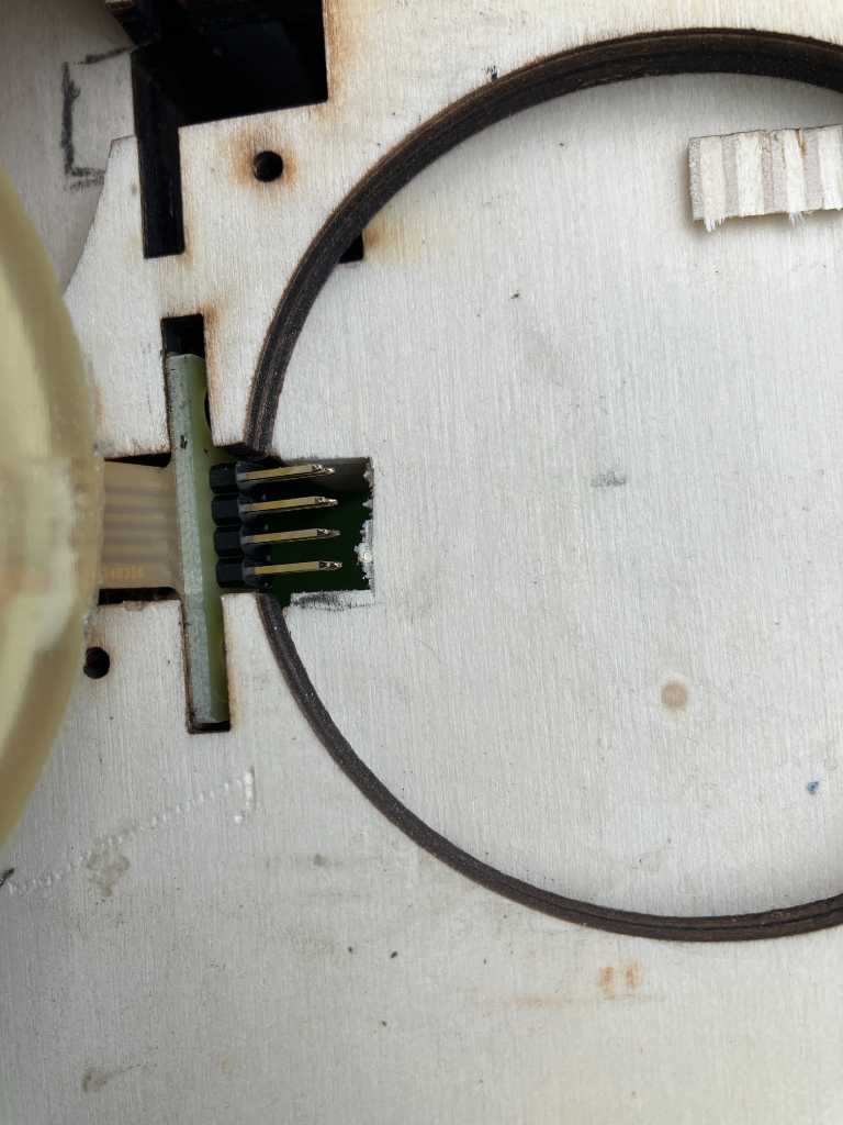
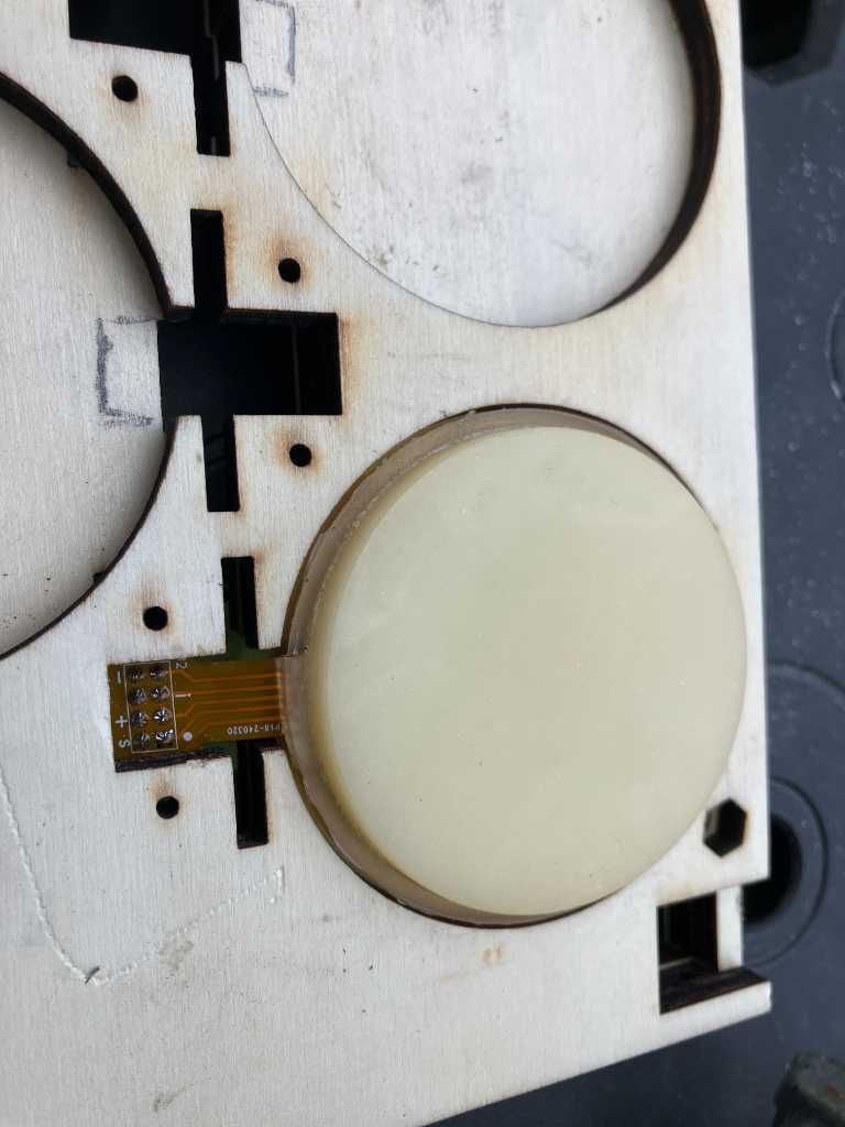
And desolder the connector from all 76 sensors and solder a connector that can be detached so that I can make a cable harness seperately:
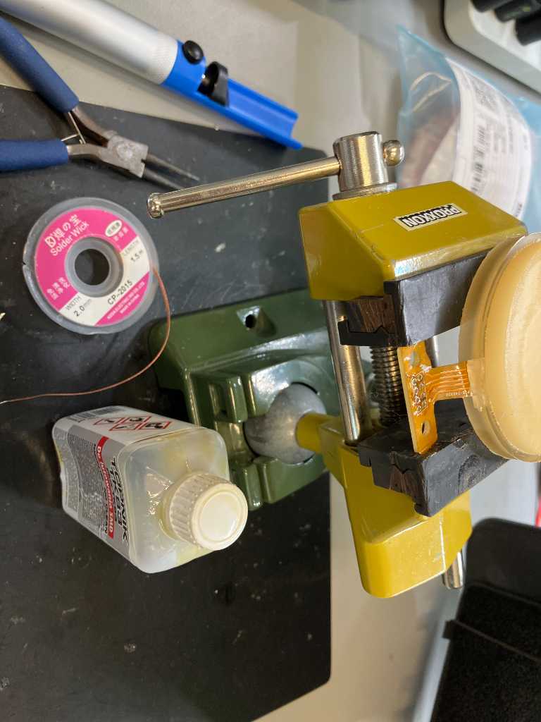
Fortunately that made it work:
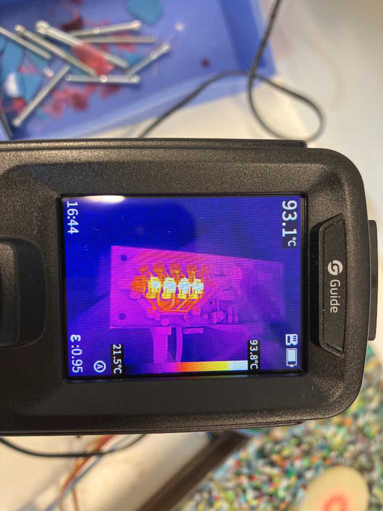
Voltage regulators getting hot
almost had a big fail by using a linear voltage regulator @ 12V going to 3.3V.
Fortunately I only used 100mA and that prevented my regulator from outputting magic smoke. I quickly fixed things by using a 5V power supply instead of 12V.
The reason why and the accompanying calculations are documentated here:
https://fabacademy.org/2024/labs/waag/students/leo-kuipers/final-project/07_electronics/#power-supply.
Now the voltage regulators still get hot, but limited to about 95 degrees C.
What I learned this week
Successes
Fortunately a lot of testing paid of. Integrating all subassemblies went pretty okay and seeing the LEDs turn on and having it send MIDI data when hitting the pads is already addictive!
Fails & Fixes
The voltage regulator that became too hot was something that is typically as “understand the datasheet”. I did read it, but hadn’t pay attention to heat dissipation. The parameters are in the datasheet, I just didn’t understand the implication. And now I do :-)
I still don’t know why the sensors ended up the wrong side up. I tested it quite a bit but apparently not correctly. So manual labor is still a necessity during digital fabrication.