networking and communications
Topic(s) of this week
- networking and communications (video, review)
- Demonstrate workflows used in network design
- Implement and interpret networking protocols and/or communication protocols
Hero shots
Assignments
Group assignment
- Send a message between two projects
- Document your work to the group work page and reflect on your individual page what you learned
Individual assignment
- design, build and connect wired or wireless node(s) with network or bus addresses and a local interface
What I think I already know
Because of my education and professional background, I’m quite knowledgeable w.r.t. networking. I’ve played a bit with I2C, SPI and used serial UART and TCP/IP networks a lot (my first network I created was back when TCP/IP didn’t use CAT cables but coaxial cable). I think I can recall the OSI layers if you’d wake me up in the middle of the night, so I should be fine this week. However, I’d rather not have you wake me up…
What I want to learn
I want to get my I2C network for my final project up & running at the fastest speed possible. That’s my main goal for this week.
SSTM planning
Supply
| Day | Supply | Tasks |
|---|---|---|
| Thursday | 08:00-09:30 (train) | finalize final project main PCB |
| 10:00-18:00 | group assignment | |
| 22:00-23:00 | documentation | |
| Friday | 11:00-12:00 (fablab) | FP casting |
| Saturday | 15:00-17:00 | FP programming WS2812B |
| Sunday | 15:00-17:00 | FP programming WS2812B |
| Monday | 9:00-17:30 (fablab) | FP casting, mechanical production |
| documentation | ||
| Tuesday | 9:00-17:30 (fablab) | FP casting, making FP main PCB |
| 20:00-22:00 | Documentation | |
| Wednesday | 9:00-12:00 (fablab) | FP casting, soldering main PCB |
| 12:00-13:00 | Local review | |
| 13:00-14:00 | Regional review | |
| 15:00-18:00 | Neil time |
Tasks
Have you answered these questions?
- Documented your project and what you have learned from implementing networking and/or communication protocols.
- Explained the programming process(es) you used.
- Outlined problems and how you fixed them.
- Included design files (or linked to where they are located if you are using a board you have designed and fabricated earlier) and original source code.
- Included a ‘hero shot’ of your network and/or communications setup
- Leave feedback in Nueval that this weekly is ready for evaluation.
WAAG session and group assignment
Edwin and Bas gave us a workshop on networking.
UART communication starts with a start bit (indicating that the receiver should start listening), it can contain a parity bit (to detect if there were errors during data transfer) and ends with stop bit(s).
For serial communication you usually see e.g. 9600,8,n,1. Meaning 9600 baud, 8 data bits, no parity bit and 1 stop bit. Baud = number of bits per second.
RS232 one has 1RX and 1TX line. RS485 is differential and uses twisted wires. This means that noise interference can be reliably filtered out.
AVR microcontrollers (like arduinos) have MPCM (multi processor communication mode). This is an addressable protocol which is all implemented in hardware. This means limited interruption on running code and limited impact on memory and program size.
Usually talking to peripheral chips like sensors, actuators, memory chips, etc. use either SPI or I2C.
SPI doesn’t have addressing. Instead it uses a chip select line for every SPI-enabled chip that it wants to communicate with. This CS line can be either high or low. When high, the connected chip will listen, otherwise it won’t. The MOSI and the MISO pins will send data at the same time. You can use that to daisy-chain. Daisy chaining is standard in the SPI protocol and you can always do that. All CC/CS lines will be connected parallel to only 1 output pin of the main controller. It does require more programming because you need to take care that the data you send is in the correct order. Remember there’s no addressing so the first chip will listen to the first package and send the rest through the other chips, etc. Comparable to neopixels.
I2C is an addressable protocol. It generally uses a 7 bit address, so 128 addresses in total. But nobody is stopping you to use 10 bit addresses. I2C does add quite a bit of overhead due to the addressing. Example of an I2C enabled device is the PCA9555 I/O expander.
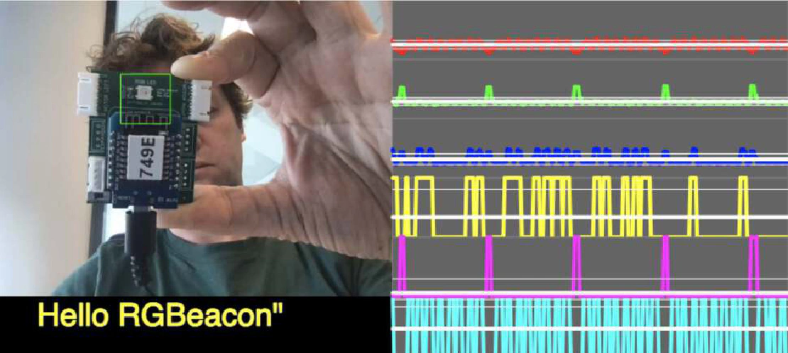
Basically anything that allows you to send 1’s and 0’s, you can do communication. To give an example of this, Bas showed what he did in his communication week: communicating by blinking colors of a neopixel.
It is good practice for I2C and SPI to use buss pull-ups and pull-downs. This fixes the bus to gnd or vcc level to ensure valid signals. The best value depends on speed.
SPI typically uses 10k pull down (mode 0)
I2C typically uses 4k7 pull-up
you also need to take care of bus termination. Long communication wires need this because the capacitance (and inductance) come in to play. You’re talking about many meters. Wires carrying high frequency (many kHz) require this too. This is to prevent reflections and provide a good impedance. A wire acts as a capacitor with a resistor and as such is a low-pass filter, preventing high frequencies.
Send a message between two projects
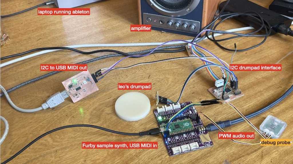
My final project is all about detecting hits and sending them via MIDI. Edwins final project is all about creating a Furby MIDI synth that accepts MIDI. So let’s combine these two!
I did this group effort together with Edwin Dertien.

from Edwins documentation
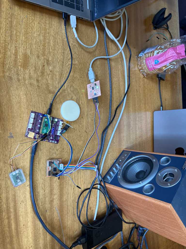
The result:
This combination is actually using 3 microcontrollers that are interconnected through different communication systems:
- A SAMD21 microcontroller set up as I2C Peripheral that captures pressure sensor data and when a hit is detected it keeps it in memory until it is requested by a I2C Controller
- A SAMD11 microcontroller set up as I2C Controller that continuously asks the I2C peripheral if it has detected a hit and when it does, it retrieves this information and sends it out via USB using MIDI Serial UART
- A Raspberry Pi Pico set up as MIDI Serial UART that listens to MIDI data and as soon as it receives note information, it “converts it” to audible sound where the velocity of the note determines the pitch of the note.
And actually there’s a 4th “microcontroller. This is my computer that is used as a “bridge” between the 2 USB devices (PICO and SAMD11). Both are set up as USB midi devices and I’m using Ableton on my computer to receive MIDI from SAMD11 and directly sending that to the PICO.
Next we want to do it without this intermediate. So a UART using I/O pins. Edwin is programming this on the PICO. I’m programming it on my SAMD. I’ve created this SAMD11 PCB in week 6 when I just wanted something that can blink an LED. I only though about the other connections a little bit, but didn’t anticipate that I’d use this board for hardware UART. And so this is the time when I got burdened by it.
As always, there are certain hardware pins (I/O) predefined as default for certain functionality, e.g. hardware UART. I didn’t breakout these default pins to usable outlets, so couldn’t use that. Another way is to use software UART. Basically this means that you can do UART, but a lot slower because you use software to create the UART protocol.
But there is no software UART on a SAMD microcontroller available. At least, in the Arduino framework, software UART is only available for AVR family. Maybe other families too, but definitely not for SAMD family.
A good resource that I used was this adafruit blog: https://learn.adafruit.com/using-atsamd21-sercom-to-add-more-spi-i2c-serial-ports?view=all.
For a SAMD, software serial is not really needed as every SAMD has multiple SERCOM peripherals that can be configured to work on multiple pins. But not every combination on any pin. And that was my issue…
I found out 2 things:
- you cannot have UART TX on SERCOM pad 1 or pad 3. UART RX is fine on pads 0 through 3. But no TX.
- If you use a SERCOM for some communication protocol you can’t use it for another. Make sense, but still… I use SERCOM0 for I2C communication. So that means I can’t use SERCOM0 for UART. And that immediately limits the amount of available pins for other SERCOMs.
After lots of trying and banging my head onto the table, I settled on using SERCOM1 on pin PA30 (TX) and PA31 (RX). And I couldn’t get it to work! No compilation errors, but no joy either! Finally, after 4 hours (no joke!) I found the issue. Instead of defining my serial UART like this:
Uart pinSerial(&sercom1, PORT_PA31, PORT_PA30, SERCOM_RX_PAD_1, UART_TX_PAD_0);
I should have defined it like this:
Uart pinSerial(&sercom1, PIN_PA31, PIN_PA30, SERCOM_RX_PAD_1, UART_TX_PAD_0);
See the issue? I should’ve used PIN instead of PORT. 4 hours wasted… BUT GOT IT WORKING!
That was great. At least that we we’re able to get it going was really great. The road to get there was…well… bumpy…
Link to repo
The source code of the Pico MIDI receiver can be found in the repo of Edwin.
The source code of my SAMD11 MIDI sender can be found here.
The source code of my SAMD21 Pressure sensor and I2C sender can be found here.
Individual assignment
This week is going to be all about sending the sensorboard data to my main PCB over I2C, meant to be used in my final project. I’ll have to mill, solder and program my main PCB. It will consist of a SAMD21 microcontroller.
To keep documentation in a well defined place:
- documentation of electronics for main PCB can be found in final-project/electronics
- documentation of programming for main PCB can be found in final-project/programming
For this week I managed to get I2C communication from my sensor-PCB (with a SAMD21 microcontroller) to a temporary main PCB (made using SAMD11, will eventually be SAMD21). The sensor-PCB will collect pressure data from 19 pressure sensors in a total interval of 200us. It also does hit-detection. The main PCB continuously polls the sensor PCB via I2C if a hit is detected. If so, the velocity is send to the main PCB. Next, the main PCB converts this data into MIDI note velocity (0-127 steps) and sends that out using it’s USB connector.
What I learned this week
Successes
Got it to work! And this is an essential part of my final project, so really happy that I was able to get this going. Especially the timing-aspect (sensorPCB polling sensors, mainPCB polling sensorPCB) was nice to get done, because the speed (or actually the latency) makes a huge difference if the Marimbatron is playable or not.
Fails & Fixes
on SAMD chips use PIN_PA30 and not PORT_PA30!!! That was 4 hours of my life…