introduction
The group assignment of this week is to send a message between two projects, document your work to the group work page and reflect on your individual page what you learned. As individual assignment the goal is to design, build and connect wired or wireless node(s) with network or bus addresses and a local interface.
ELRS transmitter using CRSF on Pico in action
Data received by Pico with ELRS receiver. Almost complete...
group assignment work
lecture
Lecturer for today is Erwin once more. He takes us through the subject matter at a fair pace, the slides can be found here - discussing the following points. Also Bas is present to give a demo of his incredible UART-to-Color-to-webcam-to-data project called RGBeacon. Erwin explains:
- star topology: pin level (uart, spi)
- ring topology: neopixel, SPI ?
- bus topology: I2C, wifi, (wired: hub, switch, router)
- UART (serial) Rx on Tx, Tx on Rx. Standard: 9600,8,n,1 -> 9600 bd, 8 bits, no parity, 1 stop.
- RS232 +/- 15V
- RS485 : low voltage differential (lower EMC) - twisted: (cat5) even better. (see)
- AVR MPCM (erwin’s find) - implemented in hardware
- SPI (motorola): one CS per device. MISO, MOSI (main, secondary)
- you can make SPI ring topology by having a daisy chain: MOSI-> MOSI1, MISO1 -> MOSI2, MISO2 -> MISO
- SPI applied in SD cards and displays, flash memory
- I2C (philips): 0b0100[A2][A1][A0][R/W] PCA9555 (io expander) PCA9685 (timer)
- Demo Bas: bits into colour, recognised by webcam
- start .. address+r/w .. ack/nack .. data .. ack/nack .. stop/restart
- fix default levels: SPI 10k pull-down, I2C 4k7 pull-up (wire length, speed, capacitance)
- look into termination resistors (120R) -> perhaps start experimenting with a long cable?
- TCP/IP (OSI model) XIAO WIFI (TCP/IP) -> IPV4/IPV6 not hardware decoded DEAD BEEF FEED
group work
While Joe, Joany and Vera try out I2C and UART serial, as well as bluetooth / BLE, Leo and I decide to work on USB MIDI and wired MIDI. In Leo’s final project should be able to send MIDI messages, my Furby Synth module should be able to receive MIDI messages, so it would be great if Leo could hit his drum-pad causing the Furby to sing… In prior weeks I already worked with SPI, I2C, I2S and serial uart, so I like to take up this particular challenge.
The MIDI libraries for Arduino have been written in such way that they can be used for both USB, BlueTooth / BLE Midi and wired MIDI, based on the initialisation of the library. It is an external library, there are many MIDI versions and implementations around. The simplest ones for sending MIDI over a normal output pin (either using Uart or SoftSerial) don’t require a library. It (should) also be possible to use multiple instances at the same time with this lib. A helpful project confirming this state of affairs using Pico is the PicoStep sequencer which uses both USB and wired MIDI at the same time.
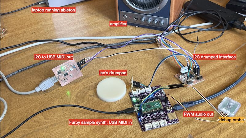
The eventual setup with Leo's pad and interface, connected to my (first) furby sampler using USB MIDI
First we try to make the USB version work. I brought the Cytron Maker Pi Pico board once more - which has a few buttons (pin 20,21,22) and a buzzer/audio jack on pin 18. My steps in changing the week6 code example are:
- trigger the sample rather than looping it continuously by adding a ‘playing’ state
- pass the playback frequency in a ‘playfurb(freq)’ function
- use the three buttons to trigger the playback
- user serial feedback (debug probe) while the tinyUSB stack takes over the USB connection
Here is the code for the first USB-MIDI test:
- midifurb.ino
- furby.h - the wav audio data as header file
First link with USB midi works quite quickly. We usee ableton (live lite 11) to connect the two USB MIDI devices. The Furby is programmed to take any note and play a sample, where the velocity is mapped to playback frequency (the harder you hit, the higher the furby sings)
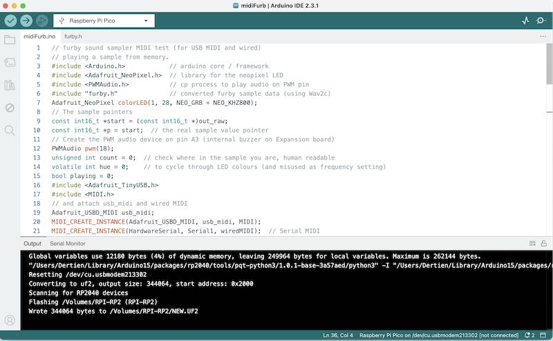
USB MIDI sources in Arduino for Pico
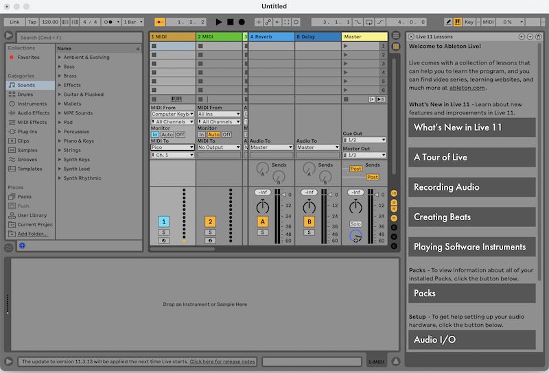
Using Ablteon Live Light to connect USB MIDI devices
In the Pico Arduino menu the tinyUSB stack is selected for USB communication. Besides that I use the PicoProbe debugger for serial communcation and programming while the USB port is in use for the music.
In order to test wired (serial) MIDI, I make a quick MIDI sender using another Pico (a Pico W in this case). The code can be found here:
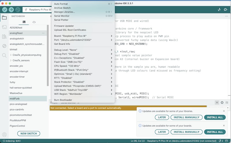
Settings for the Pico(W)
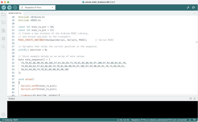
Arduino sources for Pico sending (wired) MIDI
Next up is the wired MIDI connection. First we toy with the idea of using one of the LEDs on Leo’s board as MIDI output, so I can use a photodiode as MIDI input (which is, actually, the recommended interface. Every wired MIDI input uses an optocoupler). It is, however, quite tough to find a photodiode on module with threshol/comparator. So far I know the Pico, unlike AVRs, has no inputs with built-in comparator. Next to that, Leo has exceptional trouble in lighting an LED as data output (after 4 hours of debugging it turns out he has used a PORT number where it should have been a PIN number). So, instead we use a simple wire for wired, serial 31250 bd MIDI out (Leo) to a serial input (Edwin) and make the furby sing once more.
Furby singing. How harder you hit, the higher the furby sings...
The result is not different from the USB version.. but somehow more satisfying:). As a result I now have the code for my Furby Synth to work with both wired and USB MIDI simultanously. I might go and try and expand a bit to USB host using pio next, but that’s part for the individual assignment.
individual assignment
A long outstanding wish of mine is to have a reliable radio link for my outdoor-robotics projects. After some (potentially) disasterous results with a 40MHz system indoor 12 years ago (I tried to use it to control a moving stage block carrying a Steinway Grand Piano in a monumental church) I since then mainly used 433MHz point-to-point modules, the last years mostly a nicely configurable module called APC220 by DFRobot.
In this week I would like to make (and research) an overview of current protocols and strategies. Like James Bruton mentioned in his fantastic web series: drones do not all of a sudden drop out of the air with a radio link fail. My robots struggle at theatre events when there are multiple portophones and other equipment on the same band.
Small NRF24L01 modules so far did not do the trick, and I have my doubts about ESP32 boards using WIFI or bluetooth (like) protocols. I have been using them a lot (teaching and bringing students to tears) cursing their lack of reliability and ease of debug. So. For me it’s now time to take a deep dive into ppm, sbus, csrf, express LRS, DX .. and many other protocols to find something that can
- easily connect / pair / bind
- is rock-solid (multi band, frequency hopping, the works)
- at least 12 channels (8 bit)
- at least 100 Hz
- bi-directional (I want power status and link quality info back)
In my search I arrive at the ExpressLRS (elrs) ecosystem. This is an open source long-range hi-performance control system aimed at FPV drones. Typical links have very short latency (1000 Hz update) and are (have to be) very robust. Many setup guides can be found online.
In the machine week I used a DSMX radio transmitter and receiver. This (commercial) system by spektrum is designed for RC model planes, helicopters and quad-rotors. It is using wide spectrum signals and frequency hopping in order to establish a robust connection. There is no (easy) control over link parameters, other than offered through their transmitter hardware. The point of interfacing available (at receiver side) was PPM, - basically 6 1..2 millisec pulses in a row which had to be decoded by the Raspberry Pico.
As I understand it, the way a transmitter can be configured, i.e. which channels go where, which limits, which failsaves etc. is a part of the OpenTX standard and can be configured using Lua scripting language..
Communication between the transmitter and the ELRS radio module happens with the crossfire (CRSF) protocol which needs a single uart for communication.
The ExpressLRS configurator app can be used to compile and upload software to transmitter and receiver hardware. When running the configuration app, it looks like the software is downloading sources and a virtual environment to compile code for ESP32 and flashing the code in these modules. It should be possible to download a build-chain without the tool (but might be not so convenient). For Marlin 3D print software there has been a VSCode plugin Auto Build Marlin to configure (but not very well maintained). Perhaps something similar has been built (or could be built) for ELRS.
I start with two examples I get with checking on github for CRSF libraries for Arduino. Delving into the sources shows (similar names, definitions, setup) that most CRSF library examples have a similar origin or heritage. I have tried these earlier with Arduino Micro, but unsuccesfully. I think the main clincher there is the 420000 baud required by transmitter and receiver -> something the Arduino micro might struggle with, but something the Pico should be able to do.
for the receiver:
and for the transmitter:
- CRSFtransmitPico.ino (everything in one source)
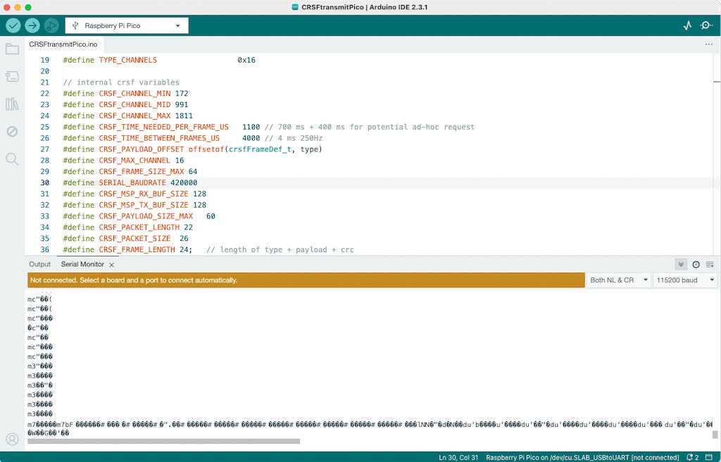
transmitter code in Arduino
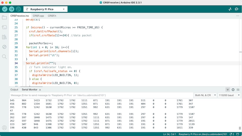
receiver code in Arduino
For the experiment I use two modules by BetaFPV, obtained through Amazon. Since the design and firmware are open, there are many suppliers offering similar modules, all equipped with Semtech Lora tranceivers such as the SX1280.
I update both the transmitter and the receiver using the configurator app - which essentially installs a full ESP32 toolchain on a ‘virtual drive’. I update the transmitter using USB connection (it can also be updated through WIFI) and the receiver using a small USB-CDC device (Silabs, the FTDI / Arduino unit did not work well). I update both to version 3.1.2 of the elrs firmware. On fora there are some posts about versions that do (and don’t) support button and OLED on the transmitter. For updating the receiver a small boot-button has to be used on-board to go into bootloader/programming mode. For updating the transmitter, jumper switches 1 and 2, 3 and 4 on the back have to be changed to go into bootloader/programming mode. Probably (have to check) to physically route the on-board serial connection to a different set of pins.

ELRS configurator platformio build environment for ESP32
Next up, I set up my week08 Pico board design to communicate with the transmitter. I use the debugprobe for flashing software. First I check serial (radio) output using the debugprobe serial port (so Pico’s USB can be used for showing data)
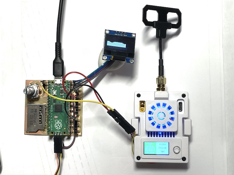
BetaFPV ELRS transmitter connected to Pico on week08 board, display showing transmitted values
BetaFPV ELRS receiver connected to Pico on breadboard
After some minor tweaking the system works (at least partially, I have to look into things in more detail). In the video you see transmitted data (16 channels), as changing pattern (sinusoidial) on the OLED display. The receiver is paired to the transmitter; to get the receiver in binding mode you have to power up and disconnect the module quickly three times. The blue LED will flash with two blinks per flash. The transmitter module can be put into pairing mode by menu options through the 4-way switch and on-board. After binding is succesful (takes some attempts) the blue LED on the receiver stays on, the transmitter tells it is ‘connected’ on its onboard OLED.
Transmitter in action
Data received by receiver. Almost complete...
other communication
I would my synthesiser Furby also speak MIDI. It is quite straightforward to make it talk MIDI of USB as USB device. The tinyUSB library contains many examples to turn the Pico into (any type of) USB device. There is also the option to use it as USB Host, but in that case an OTG cable has to be used, (USB A socket to Micro). How to make the Pico speak MIDI (and Furby) has been shown in the group assignment discussed earlier.
A different option exist where the Pico’s PIO is used to make a bit-banged USB host socket:
- PICO pio USB host: https://github.com/sekigon-gonnoc/Pico-PIO-USB
- https://hackaday.com/2022/12/28/usb-host-on-rp2040-with-pio/
I try a simple setup using the PIO pico USB host libraries from github which tie in with Adafruit’s tinyUSB library, which, in turn, should be compatible with the earlphilhower arduino pico framework.
The USB host functionality should run on two PIO cores, the handling of the callbacks is done on the second Pico core. MultiCore programming is not very difficult - sharing memory (FIFO) might be a bit trickyer. This might be something to check out for processing the audio: use one core for user input and control input, the other one for playback of audio. Something for later
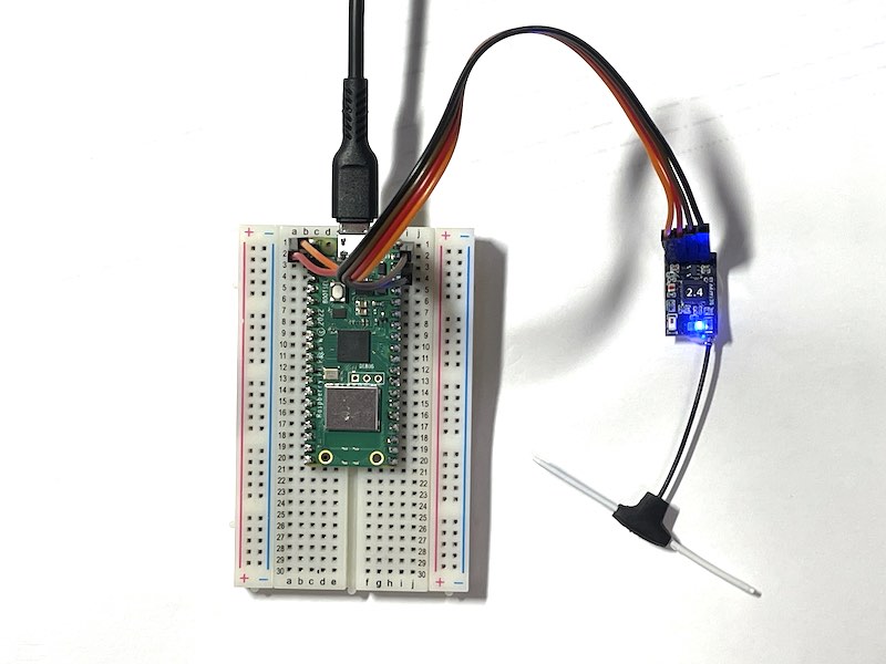
Testing USB host: pico, host cable, MIDI device, scope
In my test setup I connect an USB A socket to pin 0 and 1, VCC on Vbus. I use the debug probe for programming and for serial communciation, so the Pico’s USB socket is free to use and debug.

USB pinout
The tinyUSB library complains when compiling for host:
/Users/Dertien/Library/Arduino15/packages/rp2040/hardware/rp2040/3.7.2/libraries/Adafruit_TinyUSB_Arduino/src/arduino/Adafruit_USBD_CDC.cpp:269:2: warning: #warning "NO_USB selected. No output to Serial will occur!" [-Wcpp]
  269 | #warning "NO_USB selected. No output to Serial will occur!"
      |  ^~~~~~~
which raises the suspicion that Adafruits tinyUSB stack might want to use the regular USB socket as host so it cannot be used for CDC communication. In order to get serial debug information I route Serial1 (Rx Tx 0) to pin 12 and 13 with
  Serial1.setRX(13);
  Serial1.setTX(12);
and connect the debug probe. The code first throws a warning about clock frequency. For USB (12MHz) a clock frequency of 120MHz or 240MHz is necessary instead of the usual 133 MHz.
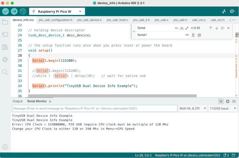
changing clock request in terminal
Next up, it seems the second core is not starting up communication, so first I add the Serial1.begin statement to setup1() and add some println statements. Eventually the core DOES start up and starts up the USB host when I change the host number to zero instead of 1.
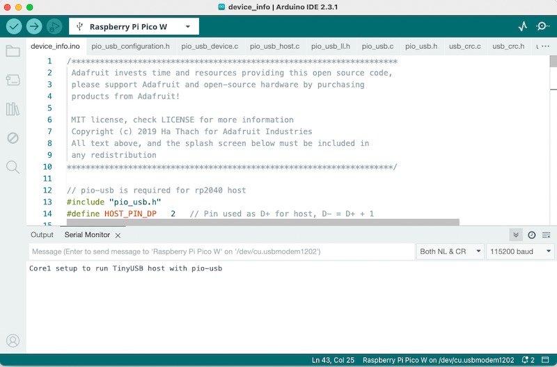
PIO USB host supposedly running on core1
Again, it might be the case that the code still wants to use the standard USB socket (which is Adafruit practice) and with the given number (1) it cannot run for some reason.
When the code is run, the host function is being called from the main loop
// core1's loop
void loop1()
{
  USBHost.task();
  if(digitalRead(LED_BUILTIN)) digitalWrite(LED_BUILTIN,LOW); else digitalWrite(LED_BUILTIN,HIGH);
}
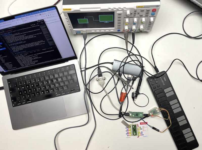
and since the LED is blinking (see oscilloscope) the code is running. However, plugging in a device, be it USB mouse, memory stick, MIDI piano or other, does not trigger any callback.

Oscilloscope probe on LED blinky -> host is running, no data on the D+ and D- lines
Forum posts are not very much enlighting here, so as alternative I try the ‘official’ Pico SDK as build toolchain and step away from Arduino (for now)..
installing Pico SDK
Ok. So forgo the Arduino environment and try to build using the Pico SDK. The manual is very good pdf. I follow the following steps:
First setting up:
git clone https://github.com/raspberrypi/pico-sdk- env (check environment)
- add
# added on 28-04-2024 by Edwin for the pico SDK
PATH="/Users/Dertien/git/pico-sdk:$PATH"
to the .bash.profile file
- env -> environment is not changed! (After googling, stack-exchanging and a whole lot of trouble, apparently the file is not
.bash_profile, not.zsh_profilebut.zshrc(!)). Now the change to the path is persistent. - I follow the next steps (make dir
buildin examples,cmake ..,make) - terminal still complains. I add
export PICO_SDK_PATH=/Users/Dertien/git/pico-sdkto.zshrc - cmake throws a lot of warnings, so I first need to check whether I installed the pico sdk correctly. Better perhaps to check everyrhing again. Follow a manual
- the ‘killer’ command I previously missed was
git submodule update --init - (and soo many sources added.. I’m curious how many GCC’s are fighting on my system)
- frustrating: every (sub)program of gcc has to be verified by MacOS and allowed through the ‘security and privacy’ settings.
- Next up I try using
cmake ..andmaketo compile Pico-PIO-USB/examples and it seems to be working!

Pico SDK installed on the system
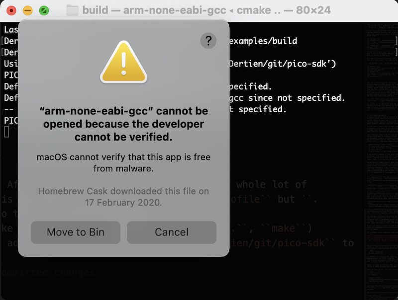
allowing every single application in the toolchain to run - and/or access to files
Next up compile and build:
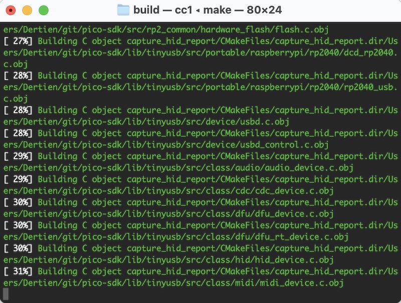
Pico SDK building PIO-USB example
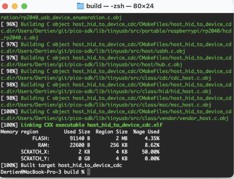
Done building
adding cmake support to vscode
From the same manual I do: mkdir .vscode cd .vscode touch settings.json
Next, I open up settings.json and add
{
    "cmake.environment": {
        "PICO_SDK_PATH":"../../pico-sdk"
    }
}
I add the Pico-PIO-USB example dir to VScode, ‘accept’ the offer to configure the project, select an example, hit ‘build’, select the arm-none-eabi-gcc compiler and watch the build complete..
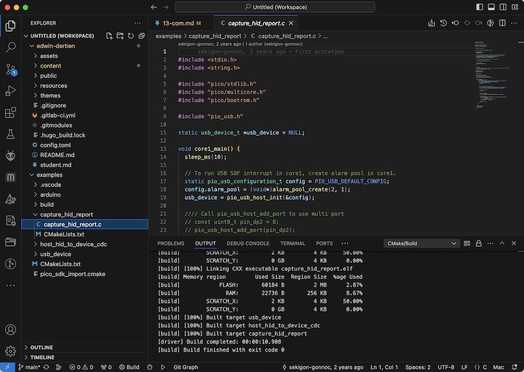
Cmake for building Pico sources (with PIO USB host) in VScode
Next up, I search in al the built examples (all examples have been built) for the appropriate *.uf2 file. I connect the pico in boot mode, drag the *.uf2 file to the disk and start up a terminal (in this case Arduino is still open). The USB memory device does not report, but the KORG nanoKEY2 I have around on my desk (the intended USB-MIDI device for this endeavour) does give a report back!
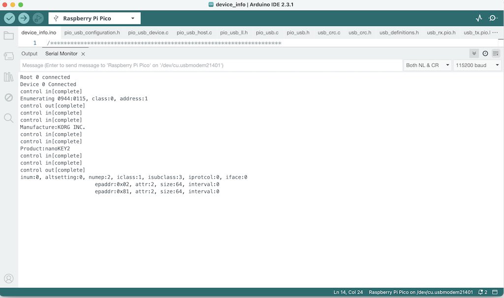
Arduino terminal showing PIO host running (compiled using PicoSDK in VScode)
Also on the oscilloscope, you can see the USB data reports coming in:
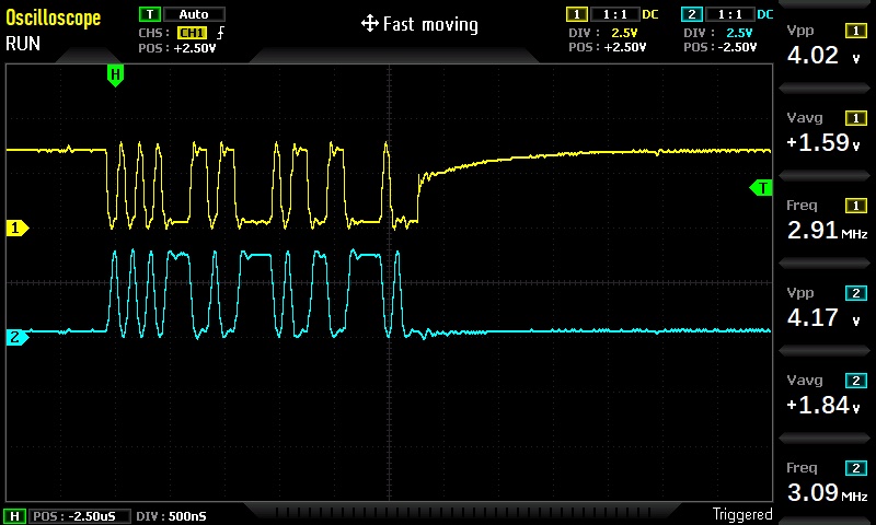
USB data: differential on D+ and D-
So. I have a basic working version. Question now is whether the tinyUSB libraries using the Arduino framework (and these PIO sources) can also be made to work (and, more importantly, assess how much work it will be to add MIDI USB support). I have succesfully worked with USB MIDI before, mostly using the USB-Host shield or Arduino MEGA ADK (using the MAX3421E USB Host controller) and using the Teensy 3.6 (with built-in host support)
learning outcomes
The goal of this week is to demonstrate workflows used in network design, implement and interpret networking protocols and/or communication protocols.
evaluation checklist
- Linked to the group assignment page
- Documented your project and what you have learned from implementing networking and/or communication protocols.
- Explained the programming process(es) you used.
- Outlined problems and how you fixed them.
- Included design files (or linked to where they are located if you are using a board you have designed and fabricated earlier) and original source code.
- Included a ‘hero shot’ of your network and/or communications setup
lessons learned, tips and tricks
(or, the most insightful mistakes I made)
- Always check definitions of PORT and pin and don’t mix them up (Leo’s lesson :P )
- When in doubt, fetch the oscilloscope (should do that more often)
- so many different ways of using the same tools. (platformio vs cmake vs arduino) - and they all use the same GCC
left for todo
- integrate sources and settings for the final project. Not sure the USB-host part is worth the effort of moving away from the Arduino-Pico framework or whether they can be integrated. still, with more build-chains (without the PlatformIO / earlfilower sources) other options might be available
- work through the rest of https://github.com/raspberrypi/pico-sdk?tab=readme-ov-file
- try the other examples from https://github.com/sekigon-gonnoc/Pico-PIO-USB
- and see why they don’t work in Adafruit tinyUSB land because people report it should be possible..
- and try my own PIO examples…
- look into baud rates of PICO vs clock speed. Can 420000 be used accurately (for CRSF) or is there an even more accurate clock (i.e. 240 MHz)
- check fresh perspectives on Arduino framework and CRSF
- get bi-directional telemetry working
- check out other projects for ELRS and pico. Since before I clung a bit to arduino, libraries and options were pretty minimal. There might be more ELRS+Pico projects out there that work (even) better…
- during the group assingment session @waag I played a bit with BLE examples for PicoW - a mouse example worked right out of the box. Might be interesting to work a bit more on this - and try BLE MIDI as well.
reflection
Arduino or Not Arduino. This question keeps popping up more frequently. Arduino is good in quick-and-dirty prototyping and testing. Libraries and support can be very quircky at times, so for more complicated things it might not be the best. Setting up a project in VScode, using CMAKE or with the Earlphilower Arduino framework still take up some time, editing makefiles (for the first) or project configuration files (for the latter). All of that is done for you by Arduino, at a price that you don’t know exactly which sources you are using from where exactly.
The ‘getting rid of the library by pasting everything in one *.ino file’ is also a sensible approach sometimes, but obviously this does not work with more complex sets of sources.
I like the simplicity of using two cores in the Arduino framework (just a setup1 and a loop1… brilliant). I also start to appreciate the power of PIO, especially when it allows me to work with my favourite USB devices eventually. For many theatrical / robotic projects I use a controller with USB Host to hook up a nice joystick, gamepad, WiiMote or MIDI control surface. Using the Pico as USB device is as easy as with any other native USB controller (I typically use Arduino Micro for this). Using the host is not (yet) as simple as with an USB-host shield on Arduino or the native USB Host support on Teensy.
Crossfire and ELRS open up a new world of (open) radio communcation, doing effectively what I have been doing with 433MHz modules for a long time (simple messages, checksums, 12+ channels, etc.) Before I will make a transfer and control more of my stage- and theatre robots with this system I need to check things like reconnection time, packet loss, duplex etc. Still, a promising start has been made.
For the final project I can at least now add simple wired and USB MIDI support. I also like the idea to have one Pico core worry about audio playback while the other is concerned with all the controls and user input, that could be a very powerful approach.