Electronics Design
Design of the development board
intro
Goal of this week is to develop your own board for embedded computing, preferably tailored towards the final project. As Group assignment the goal is to use the test equipment in your lab to observe the operation of a microcontroller circuit board (as a minimum, you should demonstrate the use of a multimeter and oscilloscope), document your work on the group work page and reflect what you learned on your individual page. As individual assignment the goal is to use an EDA tool to design a development board to interact and communicate with an embedded microcontroller
Although perhaps more linked to the theme of week 6, I would like to start to do proper breakpoint debugging as I’m probably going to need it for I2S and I2C devices. See this post and the official manual for directions how to set it up.
recitation
Recitation in the lab was by Erwin discussing all basics of electronis: Voltage, current, AC, DC, power. V=I.R, P = V. I = I^2 R, C = Q / V , I = C dI/dt. Capacitors allow dc and block ac (depends on parallel or serial) 100nF for switching noise. Polarised (electrolytic) for larger filters. Supercaps for powering devices. Some more (shorthand) notes:
- diode (one way) -> full bridge rectifier (4 diodes)
- bridge rectifier + capacitor = DC converter … - ripple dependingn on load remains
- multimeter only measures V (so A with shunt)
- oscilloscope: time base signals
- logic analyser – my saleae logic does analogue too…
- think back at the most iimportant books: Art of Electronisc.. - macaulay’s - ’the way things work’ and the philips electronics kits… (yes, yes, we also had Radio Shack and Tandy. But Philips was, well, … ours )
- KiCAD - little theory. (practical view, see individual assignment). Schematic and PCB. Schematic styles of wiring and labeling. Whatever you like, your choice.. I personally go for as little spaghetti as possible
- component library for FabAcadmey already downloaded from this repository.
- KiCAD Schematic Shortcuts I use a lot:
| shortcut | function |
|---|---|
| A | add component |
| W | add wire |
| P | add power point |
| G | grab and drag |
| M | move (component) |
| + - | zoom in / out |
| E | edit |
- track width: -> track width drop down, edit pre-defined Sizes… (!)
- design rule check: electrical connectivity and manufacturing..
- alt - 3 (3d visualiser) (view -3d viewer)
- better approach to change track widths is by making new net classes and set it up on beforehand..
- schematic: drag with keeping wires: G (D for datasheet)
- pcb D for drag instead of G for grab
group assignment
As part of the group assignment we looked at KiCAD, and focussed especially (briefly) on finding out how to change track width in PCB. Main point of consideration is that there is not an easy way to change track width after the tracks have been laid (and that changing track with in KiCAD PCB has been something that has changed vastly over time from version to version). Consensus is that it is best to set track widths through netclass settings (so you can have power lines with larger width) before you start the routing

setting track width in preferences pane
During the group assignment we used Waag’s rigol oscilloscope to take a look at three frequencies programmed in an Arduino board (by Erwin). Instead of showing these I’ll show the saleae analogue (and logic) data later on in my individual assignment, as well extensive use of my trusty Metex M3800 multimeter.
individual assignment
design breakdown
A short list of functions that should be present in my final project:
power supply / source
The furby module should be powered by the modular synthesiser bus - supplying -12 and 12V. It will need a 10-pin IDC socket to connect to the existing infrastructure (small ribbon cables). Part of the circuit then should include voltage regulating for the used microcontroller, audio circuitry and noise-free Servo control..
user input
For user input I would like to view the sample on a display and have a cursor input to select the ‘grain’ to be played. THe synth also needs something to select a file from the furby-sounds archive. As main user interface I then would like to use an incremental encoder with built-in switch and an OLED display. For the incremental encoder it should be possible to use an external interrupt. The I2C display has already been tested in week 6 on the XIAO but should also work on the pico
analog inputs
I expect to use some analogue inputs which I can control with external voltages, but also with an on-board potentiometer (such as the playback frequency). For this I need an analogue circuit (like a voltage summer) and analogue inputs on the used controller.
audio output
In week 6 I tried synthesising audio using PWM on a pin. It works quite well. For higher quality audio I might like to try an I2S DAC such as a PCM5102 or MAX98357. They usually need two wires (data, clock) and one additional sync/select line. The following guide explains PCM5102 with Pico, originally from this tutorial using circuitpython.
servo output
I plan to use small RC servos to move the beak, eyelids and eyes. I think a tendon-drive system will allow me to place the servos a bit back from the module, so servo sound will not interfere on electro(magnetic) and power consumption level. For that reason a separate servo driver board using a PCA9685 driver seems a good choice.
memory
In week 6 I stored the WAV audio file in memory. It might be good to be able to change the sample set by having all samples on an SD card. At bare minimum the micro SD card uses 4 lines (MISO, MOSI, SCK and SS) but probably more (6 lines)
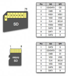
Pinout for SD card (as reference)
embedded controller
Very curious whether I will run out of pins on a XIAO. Probably. THe following pin count:
| pin count | function |
|---|---|
| 2 | I2C for display, servo controller |
| 3 | analog inputs (3 potentiometers / input control) |
| 3 | switch inputs for encoder |
| 1 | audio output (mono, PWM) or three (I2S DAC) |
| 4 | micro SD (SPI + select) |
| SWD (3 wires, separate) |
So, for now 13 connections. THe XIAO stops at 11. It might be possible to add an I2C interface for the encoder, or a voltage divider setup (as this will save 3 wires) but it might be more convenient to go for a Raspberry Pi Pico from the start. The Pico is cheaper, has more pins, better (more general) support and has a variety (Pico W) with network connectivity in case it would be needed.
On the wish-list would also be a USB host (to connect it to USB-MIDI devices directly) but no luck so far. Using Adafruit’s TinyUSB it can register as MIDI device, so connecting the module to a Host (like a computer running a DAW) is definitely an option.
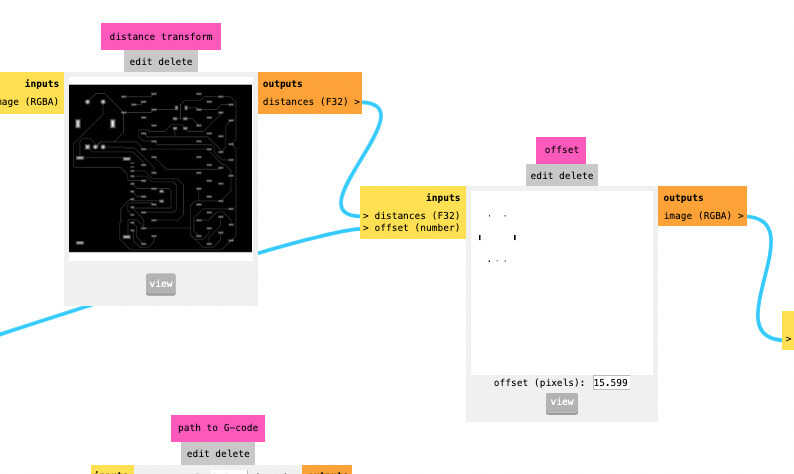
A nice overview of simple analog circuits you need for working with embedded sound synthesis is the following:
arduino IO overview and a small picture explainging offset
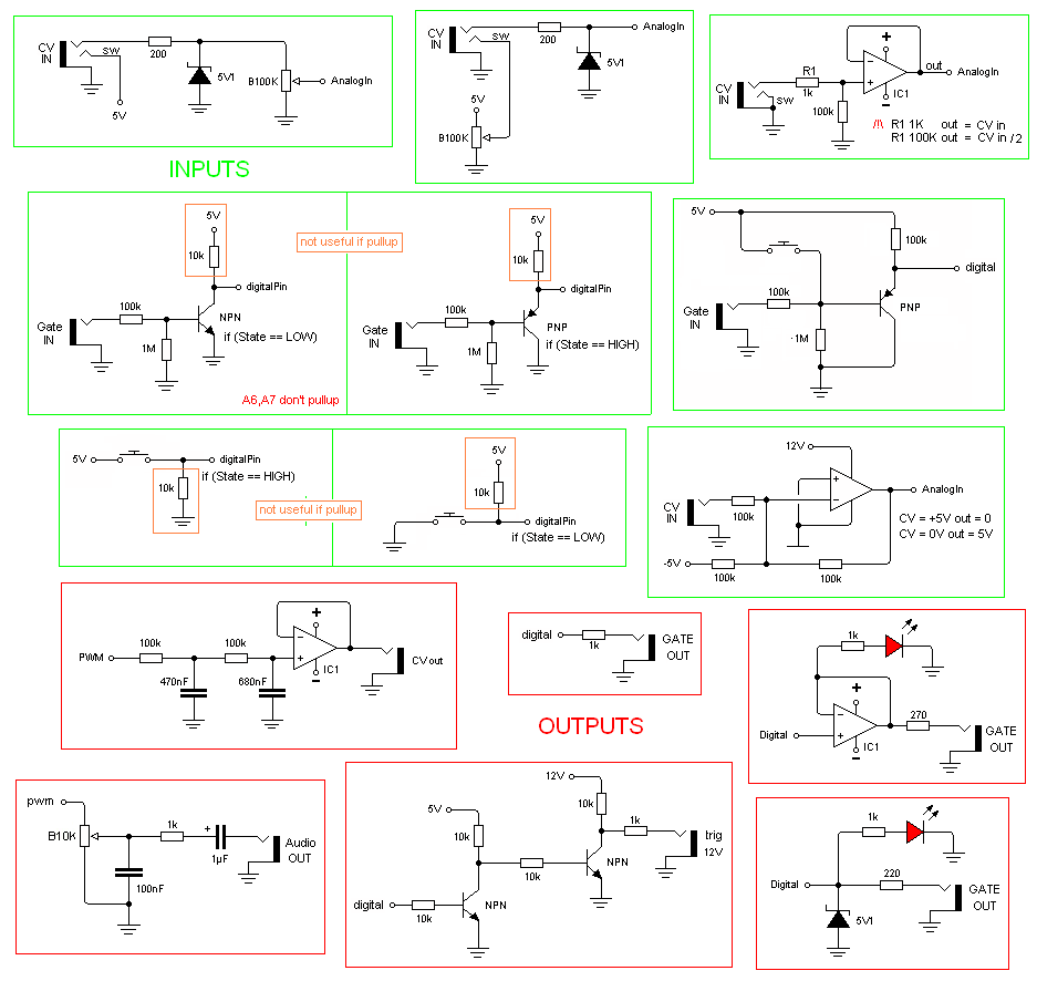
Example circuits for working with analogue signals in your embedded controller
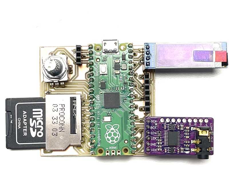
For the XIAO RP2040 I previously used an expansion board by Seeed. For the Pico I bought an expansion board by Cytron some time ago which comes in handy now. The board is very well documented The main connections on I2C (display, grove), SD card, LED, buzzer etc allow for a quick change back from XIAO to Pico with the work already done in week 6. Next up I’ll use the same connectivity as pinouts for the design in KiCAD.

Cytron's pico development board

schematic of Cytron board
KiCAD design
For the first development version of my final project I need to test connectivity and develop software for some known and some unknown components. Starting with the Pico, I’ll add the following:
- Pico: two pin rows (so I will not solder it on a board yet)
- I2S DAC such as PCM5102
- I2C SSD1306 style OLED display
- SD card (micro or normal size)
- Serial debug 3-wire socket: convenient for when USB is used for something else than USB-Serial
- I2C connector for PCA 9685 servo driver board

Working on the schematic
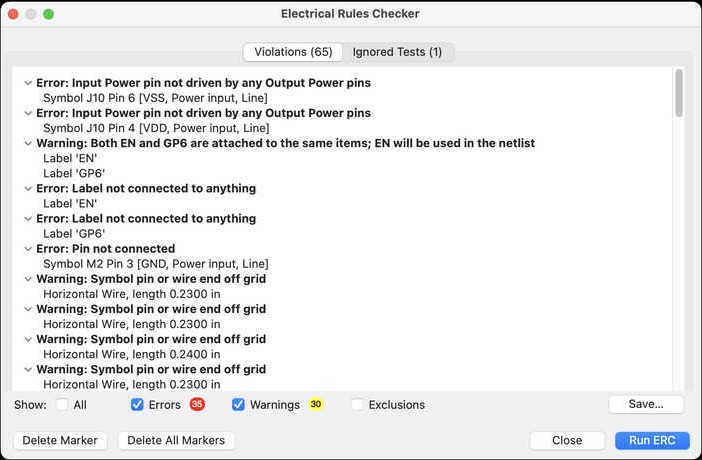
DRC for the schematic
After the design was done (and used for PCB design) I tried to clean up the work a bit for reference:
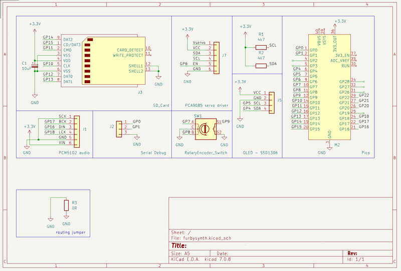
Complete schematic
Next up is the footprint assignment and assigning netclass values for routing:
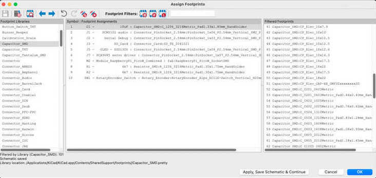
assigning footprints. Hit apply, save and continue...
Next up: importing the design in the PCB editor. The most important netclass / trackwidth settings are the track width (0.4 mm minimal) and the track clearance (say, also 0.4mm so a single 0.4 mm end mill could pass between tracks)
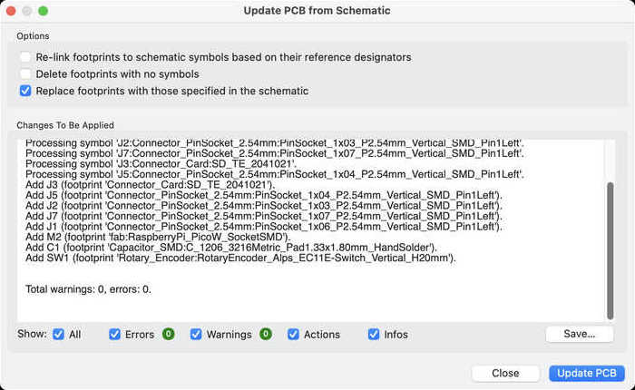
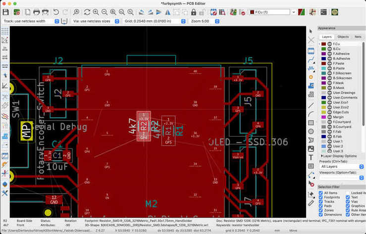
importing the schematic in PCB editor
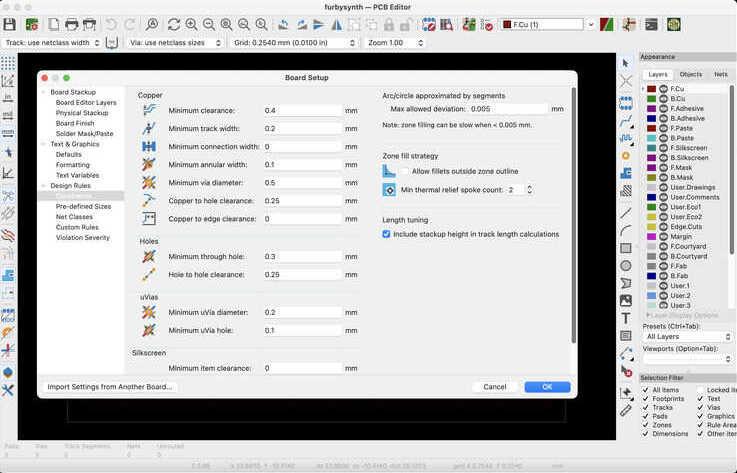
setting netclass values in PCB
Next up the routing. I didn’t use an autorouter but just the manual routing (and D (drag) function).
Ignore the warning and place components under the Pico

This point showing up in the design rule check
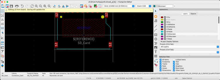
editing the footprint for the SD-card (shorter variety)

back and forth between schematic and pcb: adding a zero-jumper for the GND wire

Routing almost done, always those last two connections...

and... done :)

3D render (no time for grabcadding the other components..)
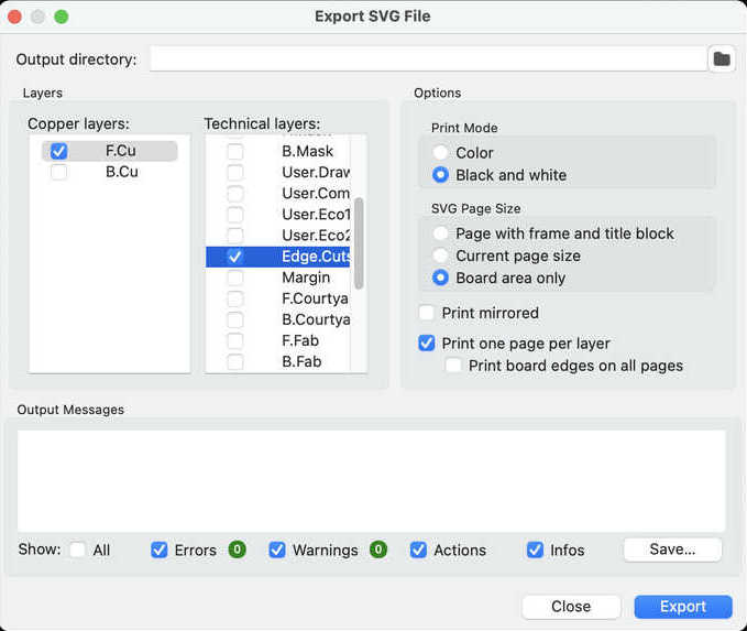
For DIY production I don't need gerbers but SVG's
(Fun fact… During week 2 I showed in the OpenSCAD tutorial a fully populated KiCAD 3D design, used to design a fitting 3D printed enclosure. The designs will be installed this week @Amos Rex in Helsinki)
Finally the design files:
- kicad schematic
- kicad pcb
- kicad project file (might be of limited use)
- pcb svg (for cutting in mods)
- pcb outline svg
- pcb track gcode
- pcb outline gcode
Open OCD for RP2040
With the Pico comes a large pico SDK. Support for the Pico debugger on platformio is still relatively new. It is documented on the platformio site. Documentation for the debugprobe using the standard pico sdk is ok see this pages but integration with Arduino IDE and PlatformIO is not straightforward yet. It is possible to program a PICO as debug probe - sources are no longer online so you have to build them - but they can also be found on archive.org. Trying to get everything workin on MacOS might prove an extra challenge Once more Max Gerhardt provides tool how to get CMSIS-DAP style SWD debugging up and running using platformIO..
checking this and using this. According to this it should be possible :) (but perhaps not on macos)
Dertien@MacBook-Pro-3 ~ % openocd
Open On-Chip Debugger 0.12.0
Licensed under GNU GPL v2
For bug reports, read
	http://openocd.org/doc/doxygen/bugs.html
embedded:startup.tcl:28: Error: Can't find openocd.cfg
in procedure 'script'
at file "embedded:startup.tcl", line 28
Info : Listening on port 6666 for tcl connections
Info : Listening on port 4444 for telnet connections
Error: Debug Adapter has to be specified, see "adapter driver" command
embedded:startup.tcl:28: Error:
in procedure 'script'
at file "embedded:startup.tcl", line 28
Dertien@MacBook-Pro-3 ~ % arm-none-eabi-gdb --version
GNU gdb (GNU Tools for Arm Embedded Processors 9-2019-q4-major) 8.3.0.20190709-git
Copyright (C) 2019 Free Software Foundation, Inc.
License GPLv3+: GNU GPL version 3 or later <http://gnu.org/licenses/gpl.html>
This is free software: you are free to change and redistribute it.
There is NO WARRANTY, to the extent permitted by law.
Dertien@MacBook-Pro-3 ~ %
(so both gdb and openocd have been installed)
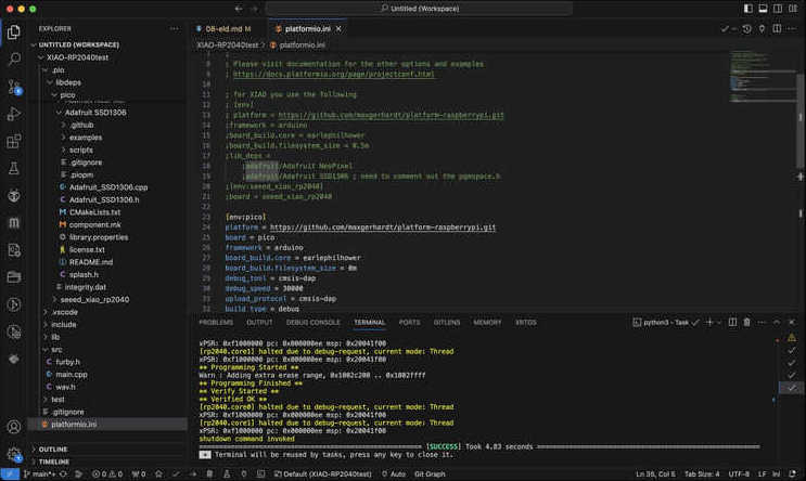
and for the platformio.ini:
[env:pico]
platform = https://github.com/maxgerhardt/platform-raspberrypi.git
board = pico
framework = arduino
board_build.core = earlephilhower
board_build.filesystem_size = 0m
debug_tool = cmsis-dap
debug_speed = 30000
upload_protocol = cmsis-dap
build_type = debug
lib_deps =
	adafruit/Adafruit NeoPixel
	adafruit/Adafruit SSD1306 ; need to comment out the pgmspace.h
monitor_speed = 115200 ;for the pico probe to work at 115200 serial debug
So. For now stuck. Eventually I tried asking help at the developer through github…, see below in the ’testing and debug’ section.
usiing the fab SAMD SWD device
The SWD programmer (we soldered in boot week) is documented here using the arduino SAM core. Overall the support using the fablab SWD debugger based on SAMD11, used to program other SAMD chips in the Arduino environment is quite ok, there are many examples. However, using the SAMD11 board SWD programmer as more generic CMSIS-DAP programer is a bit unfinished….
For the first tries addressing the Fab SWD programmer as cmsis-dap style debugger results in warnings. THe programmer seems to be working fine when used in the Arduino environment. Possible reasons might be:
- the cli invocation
- using openocd and / or ebfd
- using the wrong *.cfg file
For now I’ll first try to get a better known debugger for Pico working: the Pico (or pico probe) - as they use a similar protocol and might have better integration with VScode. Later I might try and get the fab SWD programmer working beyond Arduino + SAMD11
manufacturing the board
The board has been produced using genmitsu 2030 (at home), with the procedure as described in week 04 (electronics production.) Fortunately I used the collet/chuck the right way this time, so the milling machine eventually behaved well, especially with the V-bit. The results with the tapered ball-nose were less satisfactory.

milling pattern generated in mods
Milling the board
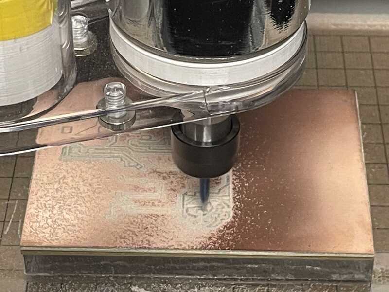
Milling the board
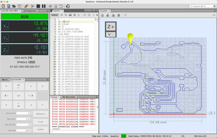
UGS for milling the board
mods was not behaving well. The gcode pcb setting did not add offset for SVG, so I could only do a single pass I used the setting for the bantam instead (modela does not save gcode)
- 4 pass using 0.25 mill setting (0.25 ball nose) - not a nice cut at all
- swapped with 0.15 v-bit. Worked perfectly
- milled wrong board stock. for some reason FR4 crept in. Beautiful result. only smelled it too late
offset in mods only negative (in G-code PCB setting)
With bantam settings I had to kill all machine specific G codes in the header part. G21: aargh.. everything imperial..
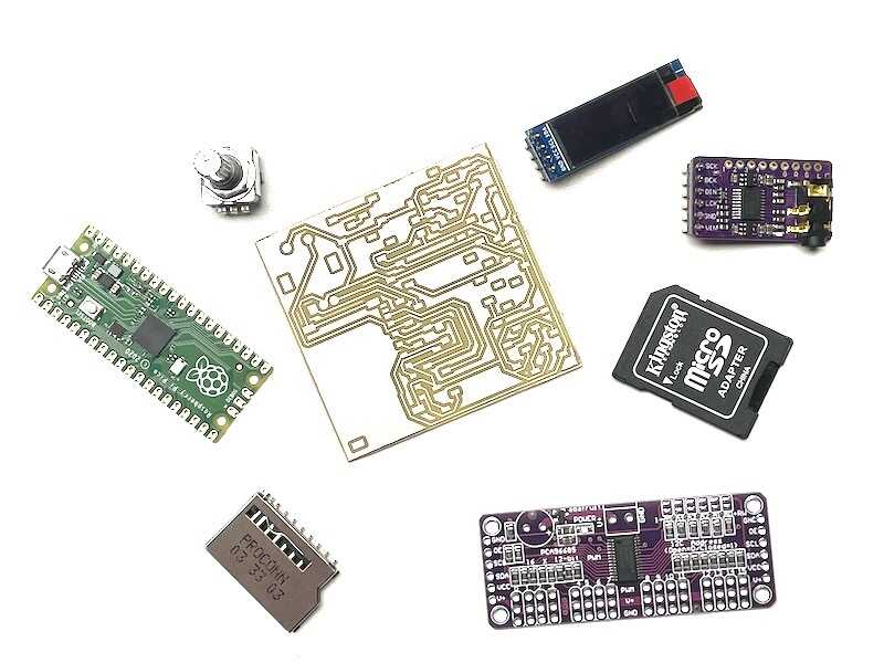
PCB and components
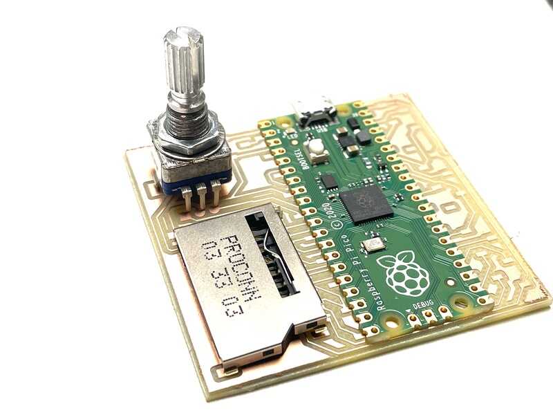
checking components for size
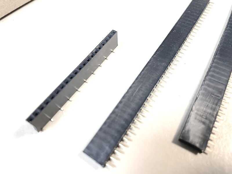
The SMD versions of the pin sockets were made from standard header
Assembled the board (1206 components under the microscope).
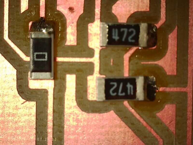
1206 components one side soldered (under microscope)
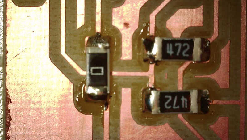
1206 componetns fully soldered
The components fit on the board as follows:
PCB with all intended components
testing the board
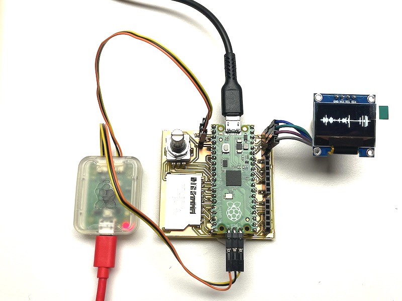
The first debugging part was done with a simple multimeter. Conductivity test (and checking) proved no shorts or wrong connections (for now). However, the pinout for the display header was (apparently) done for a different version of the SSD1306 OLED. The power pins had been swapped, so sadly I could only use the socket using four jumper wires.
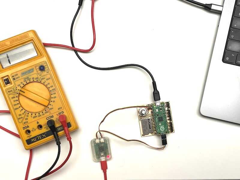
connectivity test using the multimeter
Next up I tested using the software designed in week 06. The program and debugger connection steps are described below. I used a Saleae logic debugger (with analogue inputs, so basically logic analyser and low-voltage oscilloscope in one) to check the output signals.
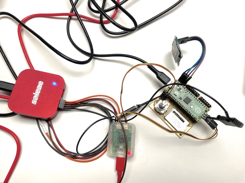
Saleae mixed signel analyser connected

debugging serial output: 'echo' at 115200 bd
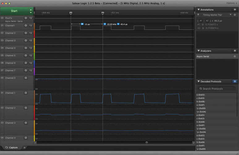
frequency of PWM audio out (22.050 kHz)
The analog input also shows change in PWM dutycycle (which we perceive as Furby Audio)
pwm audio

test program
Simnilar test program as used before: testing PWM audio out and I2C display. Next to come are the servo driver, SD card support and external audio DAC.
// furby sound sampler audio test with OLED display
// playing a sample from memory.
#include <Arduino.h>            // arduino core / framework
#include <Adafruit_NeoPixel.h>  // library for the neopixel LED
#include <SPI.h>                // not used but necessary for other displays in the SSD1306 lib
#include <Wire.h>               // the I2C communication lib for the display
#include <Adafruit_GFX.h>       // graphics, drawing functions (sprites, lines)
#include <Adafruit_SSD1306.h>   // display driver
#include <PWMAudio.h>           // cp process to play audio on PWM pin
#include "furby.h"              // converted furby sample data (using Wav2c)
// initialise limor's stuff
Adafruit_NeoPixel colorLED(1, 12, NEO_GRB + NEO_KHZ800);
Adafruit_SSD1306 display = Adafruit_SSD1306(128, 64, &Wire);
// The sample pointers
const int16_t *start = (const int16_t *)out_raw;
const int16_t *p = start;  // the real sample value pointer
// Create the PWM audio device on pin A3 (internal buzzer on Expansion board)
PWMAudio pwm(A3);
unsigned int count = 0; // check where in the sample you are, human readable
volatile int hue = 0;   // to cycle through LED colours (and misused as frequency setting)
void cb() {             // thread process to do audio update regularly
  while (pwm.availableForWrite()) {
    pwm.write(*p++);
    count += 2; // was 2
    if (count >= sizeof(out_raw)) {
      count = 0;
      p = start;
      pwm.setFrequency(22050+hue*120);
    }
  }
}
// now for the code
void setup() {
  pinMode(11,OUTPUT);         // power pin for Neopixel LED on XIAO
  digitalWrite(11,HIGH);      // turn on the Neopixel power
  pinMode(25,OUTPUT);         // blue LED on XIAO
  colorLED.begin();           // INITIALIZE NeoPixel strip object (REQUIRED)
  colorLED.show();            // Turn OFF all pixels ASAP
  colorLED.setBrightness(50); // Set BRIGHTNESS to about 1/5 (max = 255)
  display.begin(SSD1306_SWITCHCAPVCC, 0x3C); // Address 0x3C for 128x32
  display.clearDisplay();     // start the screen
  pwm.onTransmit(cb);         // start the audio playback
  pwm.begin(22050);           // set the playback frequency
  Serial1.begin(115200);      // Serial debug for the debug probe
}
void loop() {
  display.clearDisplay();
  for(int i=0;i<display.width();i++){   // this is for building up a sound wave picture
    int p = sounddata_length/display.width(); // scale the data to the full screen width
    display.drawLine(i,display.height()/2+out_raw[i*p]/4, i,display.height()/2-out_raw[i*p]/4, SSD1306_WHITE);
  }
  int cursor = display.width()*count/sounddata_length;
    display.drawLine(cursor,0, cursor,display.height(), SSD1306_WHITE);
    display.display(); // Update screen with each newly-drawn line

  static unsigned long looptime;
  if(millis()>looptime+99){ // run this code at 10Hz
    Serial1.println("echo");// printing "echo" at 10 Hz
    looptime = millis();
    hue+=10;                // cycle hue value for RGB LED
    if(hue>255) hue = 0;
    if(digitalRead(25)) digitalWrite(25,LOW); // blink the LED, 5Hz
    else digitalWrite(25,HIGH);
    colorLED.setPixelColor(0, colorLED.Color(hue,255-hue,0)); // Set pixel 0 to a color between red and green
    colorLED.show();
  }
}
Programming the board using Arduino worked well (also using the debugprobe):
board with debugprob

uploading RP2040-Pico code using the debug probe
Next up I tried to set up everything for breakpoint debugging using VScode, PlatformIO and RPI Pico RP2040 support.
uploading code using the debugger
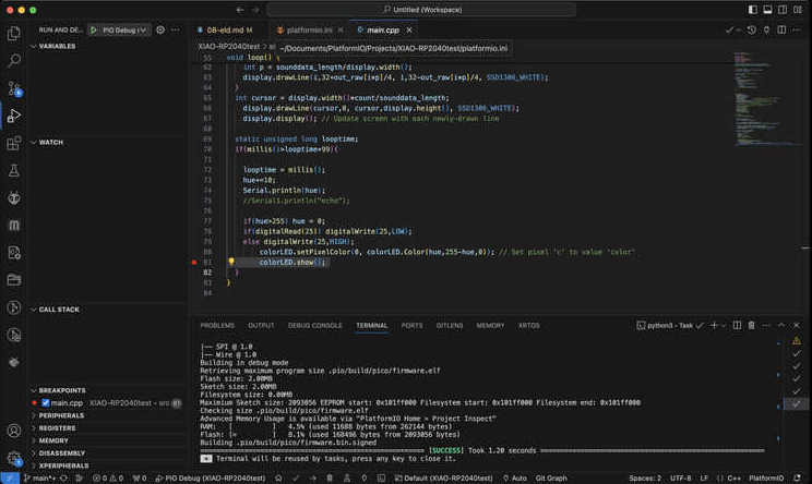
setting a breakpoint (attempt)
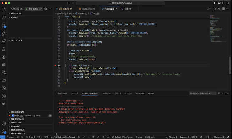
GDB does not work, segmentation fault
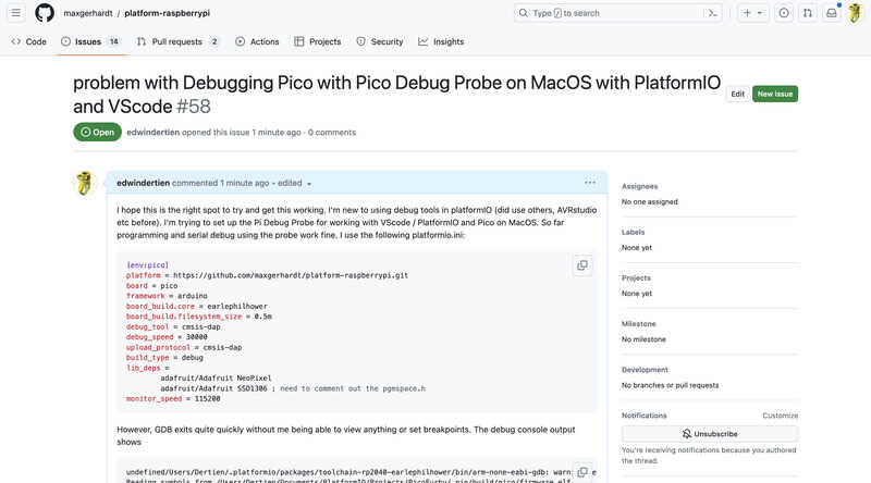
request for support filed at github
learning outcomes
Goal of this week is to explore tools (EDA) for electronics design, design, build and test a development board:
- Select and use software for circuit board design
- Demonstrate workflows used in circuit board design
evaluation checklist
- [-] Linked to the group assignment page
- Documented what you have learned in electronics design
- Checked your board can be fabricated
- Explained problems and how you fixed them.
- Included original design files (Eagle, KiCad, etc.)
- Included a ‘hero shot’
lessons learned, tips and tricks
(or, the most insightful mistakes I made)
- Wrong connector pinout for I2C. Never trust a ‘component picture’ from a random site
- pinouts of the zig-zag style SMD pin sockets don’t allow for easy soldering when they are placed closely together.
- finally, the milling works! (not with the ball-nose-tapered bit. the finishing is very rough)
- always check your board stock. Remove all FR4 immediately.
left for todo
- The breakpoint debugger does not work for Pico in combination with PlatformIO on MacOS. This might be a ’triple misfortune’ in tooling choice. However, I would like to use the Pico, I -think- I need breakpoint debugging and PIO debugging as soon as I start working with I2S and more demanding aspects of audio synthesis. I don’t like to switch to a windows machine for -just- this purpose, so I might have to hang in there. Breakpoint debugging using the SAMD toolchain in Arduino using the FabLab debugger works. Programming the PICO using the picoprobe debugger works. Perhaps more trying, more reading, more bug posting and bug hunting…
- more debugging and testing of interface components: input with encoder, SD card, audio with the I2S DAC and I2C servo driver.. So there is much more to come during the next sessions using this board.
reflection
This week the knowledge gap between participants @waag was rather big, so the group assignment did not work out so well as group effort. [Leo] and myself have been educated as Electronic Engineers. So it is interesting to listen to your entire job-skill-set being explained in under 2 hours. I liked the bit where we tried to get to the bottom of KiCAD idiosyncratic track-widht-setting which changes per version.
I have been designing PCB’s for >30 years, I made my own by hand-drawing, chemical etching, direct plotting, using a varieaty of tools: eagle, tinycad, OrCAD, Ultiboard, etc… For the last 10 years or so KiCAD has been my tool of choice, usually sending off PCB’s to Eurocircuits.
I am lucky enough to have a number of debug tools at my disposition in my home lab, from my trusty Metex M3800 (over 35 years old and still going strong), a small Rigol digital oscilloscope, the Saleae (official, cool brand, nice guys, buy their stuff, don’t buy the chinese clones) logic probes and the fantastic BitScopes (that sadly don’t work on macos anymore). I also liked to see my favourite books on the table at Waag. David Maculay’s mammoth-infested “The Way Things Work” (so much better than Simon & Chuster’s) and the fantastic paperweight and glue-press and all time favourite “the art of electronics”. It was nice to devote KiCAD skills to make a millable PCB in short time. I usually send boards to a boardhouse - routing single sided (with as minimal amount of jumpers as possible) was a nice and meditative exercise.