Output devices
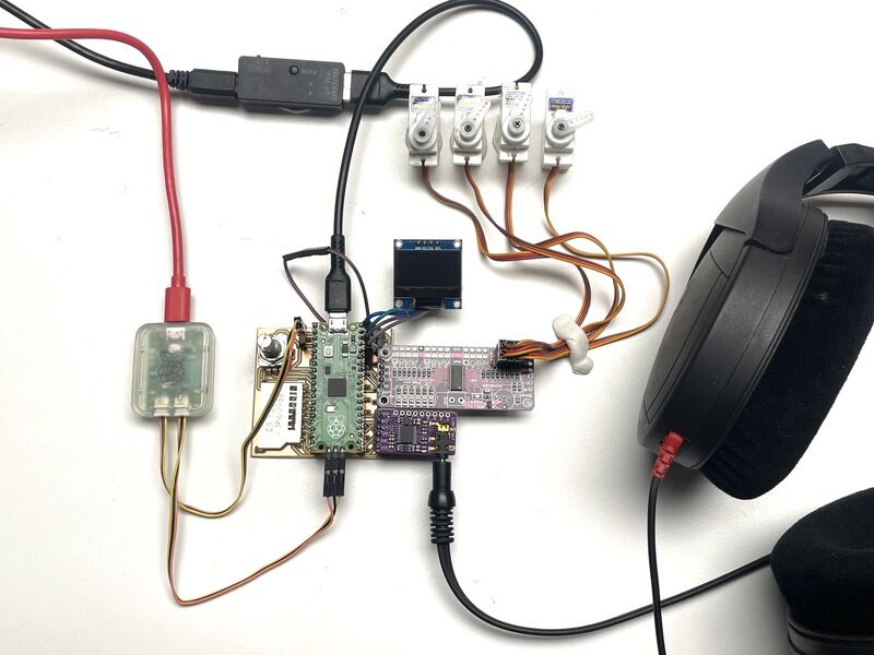
(working) setup with OLED, I2S DAC and I2C servo board
intro
The goal of this week is to demonstrate workflows used in controlling an output device(s) with MCU board you have designed. As group we will measure the power consumption of an output device. As individual assignment the goal is to add an output device to the board (shown last week) and make it do something.
I’ll need two critical output stages in my design. In week 06 I already showed PWM audio output on a pin/buzzer, in sync with data shown on the SSD1306 OLED display. For the final Furby Synthesiser module I would like to be able to control a number of RC servos, but preferably at a distance (far away from the sound and logic synthesis) in order to reduce noise. I also would like to try an I2S DAC to produce higher quality audio. Finally I would like to show servo motion in sync with audio (so I could have a beak and tongue moving in sync with the produced audio). For the session on Input I will work on the potentiometers, incremental encoder, analoque voltage (signal) inputs and SD card for audio file input.
group assignment
I followed the progress of the group this week (measuring power using USB power meter (and power supply) and connecting / controlling a stepper motor using an DRV8825 controller) remotely on leo’s page. I used the same tools to measure actuator power in my individual assignment setup. (The stepper motor results I didn’t replicate. Previous projects of mine using similar hardware, control and power consumption can be found for example here. In that specific project I choose to use RAMPS shields for placing the stepper drivers, using DMX control (30 motors in total on 6 boards using 5 stepper drivers each). Eventually we chose to use the TMC2130 instead of the DRV8825 because it offers much smoother (silent) driving and better power efficiency)
individual assignment
Let’s get the I2S audio working :) AND the I2C servo system.. in sync with audio :) Eventually for the servos I need something like this design to place them mechanically at a distance from the Furby Face. I made a boxed (enclosed) version for my own anymatronics some time ago - the design could do with an update… Perhaps this is the bit I’ll do in the wildcard week. For this week controlling servos and playing audio!
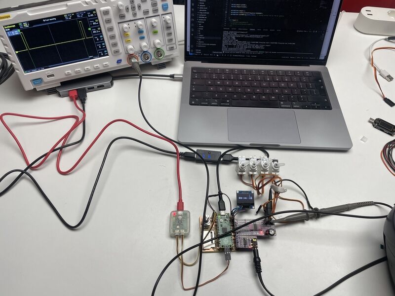
The setup in my homelab
As tooling for this week’s assignment I use a Joy-IT TC66C usb power meter. (Sadly the connectivity tools do not work (or at least, not readily on MacOS - also the IOS app does not connect at first go..) Sources can be found here so eventually it might be possible. However, cloning the repository subsequently does not allow for easy install of the ‘requirements.txt’ depenciesl through PIP. Either go for a Win10 machine (and use the precompiled executables). Next up I use a small Voltcraft PM40 USB power meter, a ADS1014D dual channel 100MHz 1GSa/s oscsilloscope (with the horrible USB-A - USB-A (aargh) cable for getting pictures out), A Voltcraft VC330 True RMS current clamp (DC) and finally my trusty Saleae Logic 8 (which can also show analogue voltages between 0..5V)
I2C Servo driver
Important consideration of the control of the RC servos is that they should not have an impact (i.e. noise) on the audio signal. The power supply for the servos should be well filtered (or decoupled) from the main power supply. Another contribution could be to separate the synthesis of the control signals from everything audio, so use a separate PWM generator to create the necessary signals.

PCA9685 module by Adafruit
Servos require a 50Hz pulse with a 5%-10% change in dutycycle (so a pulse between 1.0 and 2.0 ms wide). The PCM9685 is an I2C controlled PWM timer which can operate at different frequencies, using a 12 bit resolution. Values suggested for min- and max PWM (so 1- and 2 ms) are 150 and 600, equalling 4% and 14% duty cycle. The PCA9685 used is placed on a module on an Adafruit breakout board.
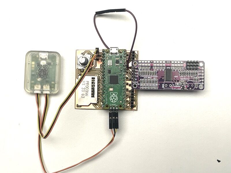
board from previous week with connected servo module
One additional change has been made on the board: a power lead has been added from Vbus (5V USB) to the Vin of the servo driver. This allows later on for placing a high side current shunt, or using a voltcraft VC330 current clamp.

Servo board wired up with 4 servos
The 1000uF capacitor that can fit on the board has been deliberately left out. I would like to try the effect of the capacitor on voltage ripple. First up the code. I first try a basic library sketch using Arduino:
Adafruit servo shield example in Arduino

lib_deps =
	adafruit/Adafruit NeoPixel
	adafruit/Adafruit SSD1306
	adafruit/Adafruit PWM Servo Driver Library@^3.0.1
In the main.cpp file in vscode I add the following lines to the top of the code:
#include <Adafruit_PWMServoDriver.h>
// Servo control through PCM9685 servi druver
Adafruit_PWMServoDriver servodriver = Adafruit_PWMServoDriver();
//Adafruit_PWMServoDriver pwm = Adafruit_PWMServoDriver(0x41); // different address
//Adafruit_PWMServoDriver pwm = Adafruit_PWMServoDriver(0x40, Wire); // different address and interface
#define SERVOMIN  150 // This is the 'minimum' pulse length count (out of 4096)
#define SERVOMAX  600 // This is the 'maximum' pulse length count (out of 4096)
#define SERVO_FREQ 50 // Analog servos run at ~50 Hz updates
Subsequently I use the following line to make sure one of the servos moves in sync with the audio: I sent the current audio sample value as position mapped to the servo scale. Eventually this yields sampling errors, and a better approach might be coding an envelope function which allows for smoother tracking.
// in void setup:
  servodriver.begin();
  servodriver.setOscillatorFrequency(25400000);
  servodriver.setPWMFreq(SERVO_FREQ);  // Analog servos run at ~50 Hz updates

  // in void loop:
servodriver.setPWM(0,0,map(out_raw[count],0,255,SERVOMIN,SERVOMAX));
The full sketch (also showing already the I2S code described in the next session) is given here:

Code in Vscode
The full main.cpp source can be downloaded here
Servo motion in sync with the audio can be seen in the following video. The audio is already played back using I2S DAC described in the next section.
Servo motion in sync with audio
The communication on I2C, shown using the Saleae Logic 8 is a bit chaotic since not just the servo driver but also the SSD1306 display is using the same I2C bus. The first picture shows all communication during a few milliseconds, the second picture one servo value written to the PCA9685.

full 20 ms I2C communication for display and driver (with 50Hz servo pulse)

One servo value written (right after the pulse)
The current draw of a servo has influence on the supply voltage. Using the oscilloscope the voltage is measured. In the following pictures you see the oscilloscope view using an ADS1014D dual channel 100MHz 1GSa/s oscsilloscope of the servo supply voltage without and with 1000uF capacitor:
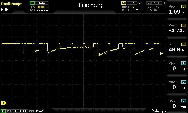
No capacitor: average voltage is 1.0V

Servo ripple with 1000uF cap: 880 mV average
The effect of using a capacitor is smaller than expected. Eventually it might still be a good idea to use a separate voltage source for the servos, separated from the audio/synth supply. The effect on the logic supply voltage (3.3V) is however neglegible:
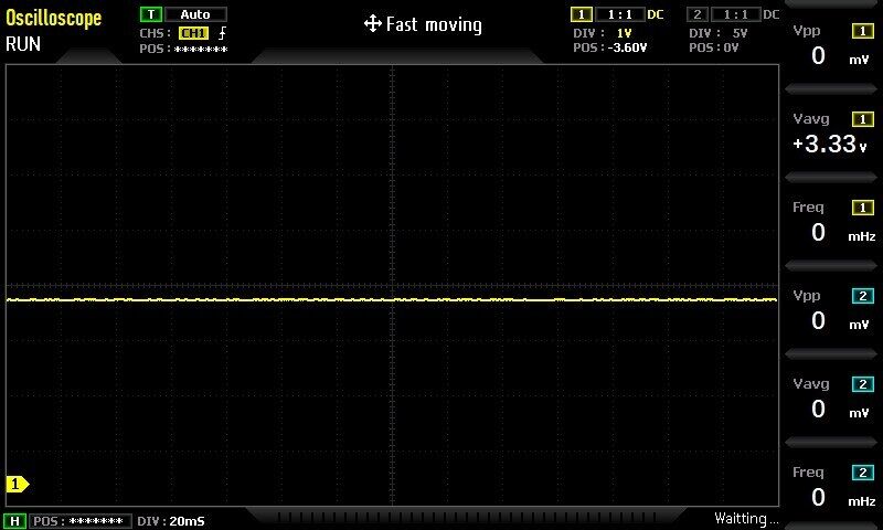
3.3V logic supply with moving servo
In the code example is described that the PCA9685 has to be tuned by setting its oscillator frequency in software - in order to make sure the output has the right Frequency. (Typically a servo will work with small deviations, but in this case it would be nice to get things right - and we do have an oscilloscope) In this case we need a 50Hz output frequency, so a divider of 27000000 is set in the example. By decreasing this value it is possible to get the output frequency closer to the desired 50Hz:
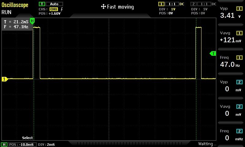
original setting of 2700000
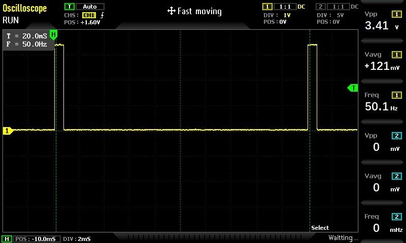
closer setting using 2540000 as PCA9685 oscillator frequency
Next up it would be nice to determine the size of the power surges, especially when the servo makes a rapid movement. The standby current of the system is 30 mA, which is current of all logic modules, PICO, LEDs (but not the servos), measured with the Voltcraft PM40 USB meter. (the meter has a very low screen update frequency, so I cannot take picture showing all 7-segment segments lit. Hence a small video)
PM 40 showing system standby current without servos
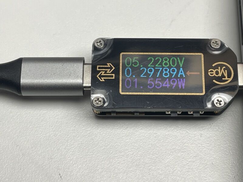
Now for the servo power surges I use a different sensor, the TC66C. This USB power data logger has USB connectivity as well as BLE connectivity. Our friends in Shenzhen however did not include drivers or software working on Macos (and the IOS app behaves quirkily). However, the display function is not bad, and it also allows for recording power consumption over a longer period of time.
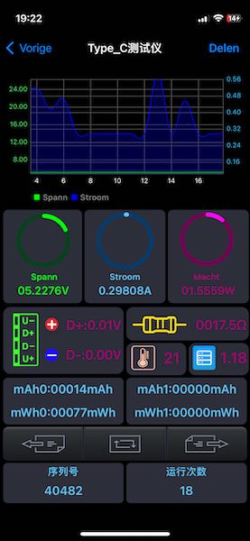
TC66C app on my Iphone 12
standby current including servos
current draw with actuated servo
This shows peak currents exceeding 600 mA, so a current draw of 300mA with respect to the standby current (of the whole system including servos, USB hub, debugger, etc. ). At 5V this results in power surges of 1.5 Watt per servo
I2S DAC
I2S is a serial protocol similar to I2C, only it is used for much higher frequency, without the addressing, so basically it is one large bit-stream on a data line, in sync with a clock, complemented by a word-address clock which switches with each completed data word (i.e. 16 bits). Mono and stereo ICs are available. Pitch space is relatively small so it might not be easy (at least in the beginning) to produce my own board. Instead (and especially for testing) I choose to use a ready to go breakout board
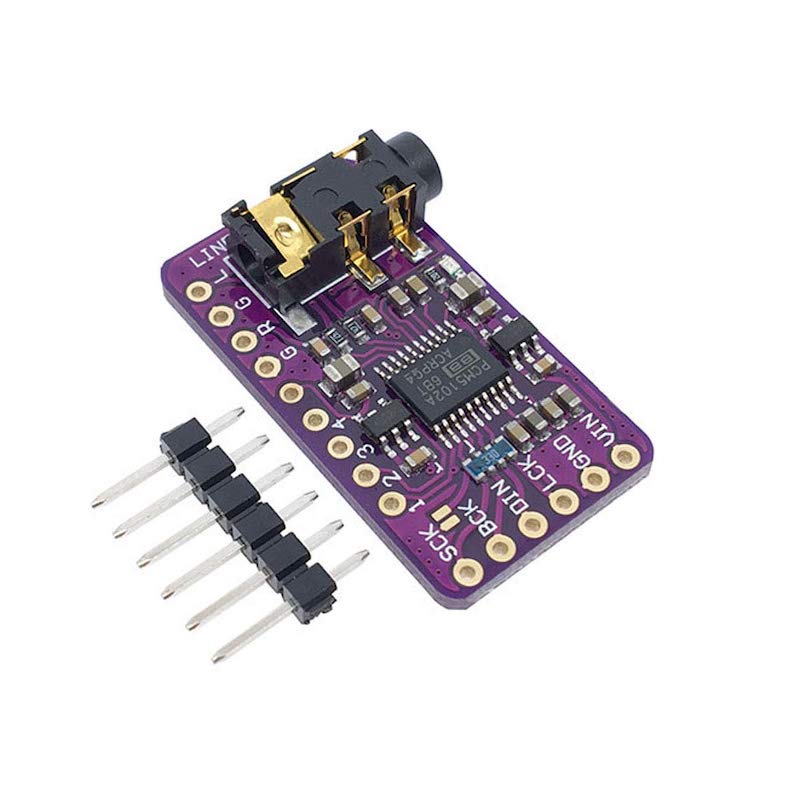
PCM5102 module
There are many I2S DAC circuits and modules available. From previous projects I have a number of unused modules available (but have not previously worked with them).. Popular are the MAX98357 which also includes a CLASS D amplifier, the UDA1334A, the module with the ADS1115 and the PCM5102 series. I need a version with line output (no speaker output) so I go for an available module with PCM5102 (stereo 16 bit DAC)- The module fits in the bottom right socket on the board designed last week. First I try a standard sketch to generate a tone which comes with the standard arduino examples.
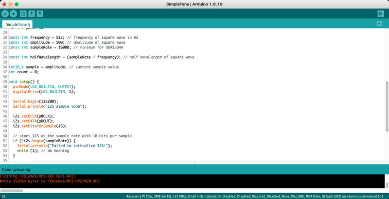
Arduino example for I2S tone
The used pins have to be changed: on my board I use pin 17, 18 and 16 for pBCLK, PWS and PDOUT. The tone function works, and (whatever you do, don’t wear the headphones during programming!!!) plays nicely on the headphones. So, next up is installing the library in platform.io and integrating the code with the previous sketch playing back *.WAV audio.
I make use of a Sennheiser HD 265 headphone to check up on the audio.
#include <I2S.h>

// Audio output through I2S: Create the I2S port using a PIO state machine
I2S i2s(OUTPUT);
// GPIO pin numbers
#define pBCLK 17
#define pWS (pBCLK+1)
#define pDOUT 16
const int sampleRate = 22050; // minimum for UDA1334A
In the PWM timer reload function (previously used for PWM audio only) I include also two I2S write actions. There have to be two, (writing the same sample in this case) to allow stereo data output on the PCM5102.
i2s.write(*p);    // write sample to left channel
i2s.write(*p);    // write sample to right channel
pwm.write(*p++);// write sample as PWM (and go to the next)
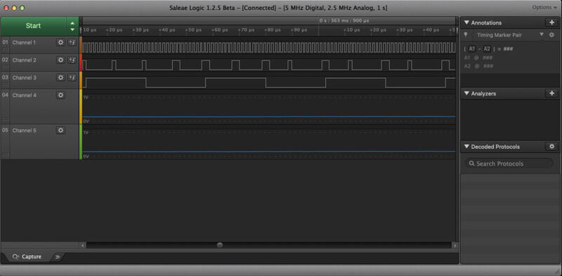
I connect once more the Saleae Logic 8 to check the signals.

Debug setup using Saleae logic 8
The saleae does a good job capturing the bit pattern. Audio is shown (as analog signals), top three rows show clock, data and word-clock.
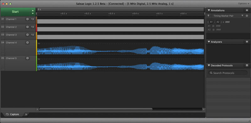
I2S audio debug
The bit patterns are not recogniseable in the previous picture (the audio however is)
I2S bit pattern on Saleae logic
The protocl analysis in Logic shows clock, data and word - sync signal. The clock (top row is 7 pulses per 10 uS, so 7kHz)

decoding the I2S protocol
The oscilloscope also shows the resulting audio. It is hard to recognise the sampling frequency back in the audio signal. Comparison between the PWM and the I2S DAC is still to be done (because it is not directly fair to compare unfiltered PWM with a filtered DAC, it would make sense to compare the PWM after filtering)

audio
Overall the I2S DAC seems to perform well, it is nice to have the option of producing high-quality audio as opposed to lower quality PWM synthesised audio. For now the amount of computation necessary seem to be withing bounds. Next up will be to check the amount of play with sampling frequency and (seamless) looping.
learning outcomes
Goal of this week is to demonstrate workflows used in controlling an output device(s) with MCU board you have designed. The group assignment is to measure the power consumption of an output device, document your work and reflect on your individual page what you learned. As individual assignment the goal is to add an output device to a microcontroller board you have designed and program it to do something.
evaluation checklist
- [-] Linked to the group assignment page.
- Documented how you determined power consumption of an output device with your group.
- Documented what you learned from interfacing output device(s) to microcontroller and controlling the device(s).
- Linked to the board you made in a previous assignment or documented your design and fabrication process if you made a new board.
- Explained the programming process/es you used.
- Explained any problems you encountered and how you fixed them.
- Included original source code and any new design files.
- Included a ‘hero shot’ of your board.
lessons learned, tips and tricks
(or, the most insightful mistakes I made)
- it was very helpful to have checked pinouts for components such as I2C and I2S using devices in other designs prior to selecting pinouts in the board design last week. Besides the I2C header for the OLED display (which had VCC and GND swapped) the pinout of the other sockets was correct.
- placement of the two lower boards (servo and I2S DAC) could be better, there was very little spacing
- it would have been nicer on the MCU board to have more exposed pins other than the selection I made for devices specifically. Now the function is limited to the very modules I selected rather than more generic or general purpose
left for todo
- (breakpoint) debugging the Pico in VScode/platformio still does not work. However, the debug probe is very fast with programming and it is nice to have an additional serial port. Next session on input and/or communciation I would like to add a USB MIDI input, so then a separate serial debug port will come in handy anyway.
- decide whether to use the PCA9685 IC and PCM5102 IC directly on a board or keep using them as modules
- I need to add tracks or inputs for other servos too, and with 4 servos (6 watt power surges) work even more on filtering power supply noise
- for the servo motion I need to program an envelope function to create nice synhronised motion of for example the beak
- SD card input, potentiometer input, encoder input and analog control voltage input (trigger, CV, modulation) have to be added (input week)
- MIDI USB interface has to be added (communication week)
- servo tendon drive mechanism has to be added (wildcard week)
reflection
Due to other obligations I could not take actively part in the group assignment this week. Instead I tried to make amends by measuring power (and discussing power ripple/noise) in relation to my own final assignment. I was very happy the I2S DAC and I2C servo modules worked without too much hassle, and closer inspection using oscilloscope and logic analyser showed them also working as expected. I expected more influence of the 1000uF capacitor on the servo board, so it might be interesting to use the same setup and try different capacitors / combinations to try and filter out the worst. Time-supply wise this was not the most intensive week (due to said other obligations: I had to install custom audio player hardware for an art show at Amos Rex, Helsinki Finland. Also interesting PCB design work, see this page. I even managed to visit the Public Library at Helsinki which also offers a great publically accessible fabrication space). However, I am very happy with the end result, because it is a great step towards what I need for the final project
copyrights and references
- I used standard module / board pictures of the PCM5102 and PCA9685 modules from online supplier (amazon)