introduction
Goal of this week is (as a group) to design a machine that includes mechanism + actuation + automation + application. Build the mechanical parts and operate it manually and document the group project, also documenting your individual contribution to the project. The second part consist of actuating and automating the machine, documenting this in the group project and once more documenting the individual contribution.
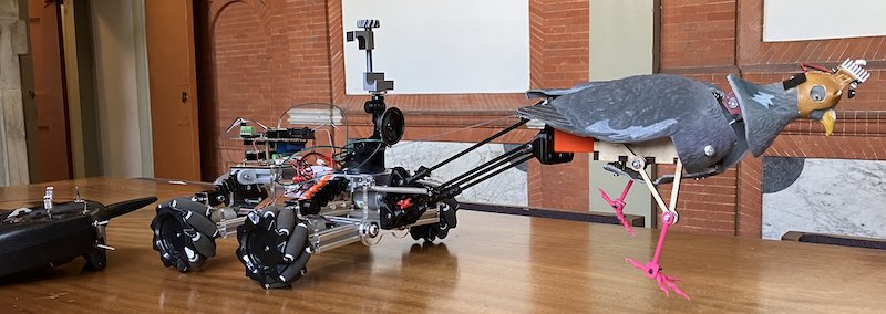
Hero shot of the full Real Urban Pigeon Eye View machine
The final video (with a big thanks to Leo) can be found here
The result of brainstorming is clear, entertaining and exciting. We are going to mingle in the famous ‘Pigeons Aren’t Real’ conspiracy theory by building a robot pigeon that can mingle between the real (or fake) pigeons crowding the Amsterdam ‘Nieuwmarkt’ where Waag is located. We will use this robot to study pigeons up close with as aim to film a documentary, much like the ones made with penguins in the Arctics.
Puppetmaster robot and mechanical pigeon
The project is named RUPEV (Real Urban Pigeon Eye View) so we can work on exiting systems such as the DPSS (Dynamic Pigeon Stablising System) or the PPPMPCS (Pico PPM Pigeon Control System). (We are still dealing with an official warning we received from the AAAAA (American Association Against the Abuse of Acronyms) claiming we were making fun of the whole thing…).
As task division in the project (and links to individual pages)
- puppet master robot, omniwheels, RF & programming Edwin
- puppet master robot, PCB, springs Vera
- head movement, audio, legs Joe
- mechanical leg movement, body fixture, movie, script and editing Leo
group process and planning
After a short lecture by Saco on machine design, overconstraint/underconstraint designs, error chain (series, parallel mechanism), precision, accuracy and resolution - we launch in a functional system breakdown and MoSCoW requirements specification prioritisation. The full list is documented on Leo’s page and on the Group page.
Spiral 1:
With materials available @Waag we decide to build the simplest version possible (or our Minimal Viable Product) and take it to the streets as quickly as possible, consisting of
- a faux pigeon
- 4 wheel driven cart
- control input
- camera (mount)
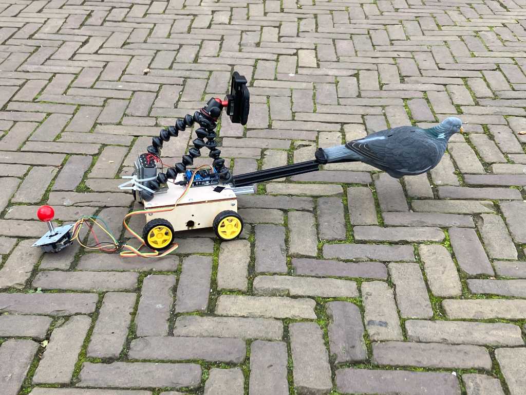
First incarnation of RUPEV, picture by Leo
While Leo and Joe consider 4-bar linkages in simulation to create a mechanical pigeon motion system (moving legs and moving head), Vera and I team up to build a robot cart for pigeon propulsion and overhead (3rd person, not-birds-eye-view) camera.
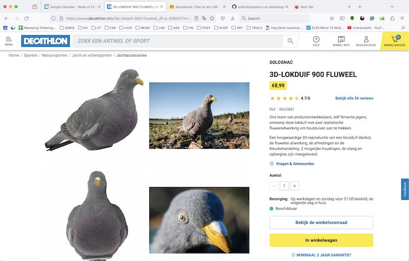
Pigeon supplier: in stock just 12 minutes away
The Faux pigeon is acquired at a sports shop 12 min cycling away. (it is the (last) one, the shop team says reluctantly goodbye, it has been their mascotte for some time now (luring pigeon, apparently for hunting (?) purposes)
Decathlon support team saying goodbye to their pigeon....
We find the following suitable materials at Waag:
- 4 jameco 12V geared DC motors with 1:50 reduction.
- Adafruit Motorshield (2009 edition) using Arduino and Adafruit library. This motor shield fits on an Arduino Uno and uses two L293 double H-bridge drivers, controlled by a shift register (hence the library)
- Arcade joystick (switch based) on port A0-A4 (digitalRead) with a 1m flatcable
- 12V battery by soldering 4 2-AA holders together (old AA re-used)
- some bars of 200mm x 20x20 aluminum extrusion profile
- 4 standard yellow 60mm plastic robot-kit wheels
- a gorilla camera tripod with phone-clamp

schematic of adafruit motorshield
The DC motors by Jameco have an off-center drill pattern. Sadly not easy to mirror: some of the mounting holes (m3) are just a few mm deep. In the others you can (apparently) turn a screw all the way INTO the gearbox, eventually locking (or demolishing) it.
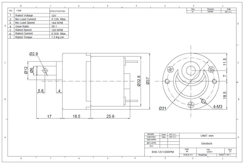
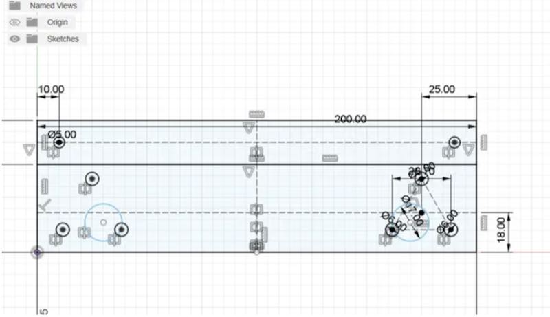
dimensions for the Jameco 12V geared motor
Vera designs the side plates to mount motors in Fusion, to be cut out of scrap wood on the big laser. I write a quick sketch using Arduino environment to control the 4-wheel cart.
Design in fusion of side plates (vera)
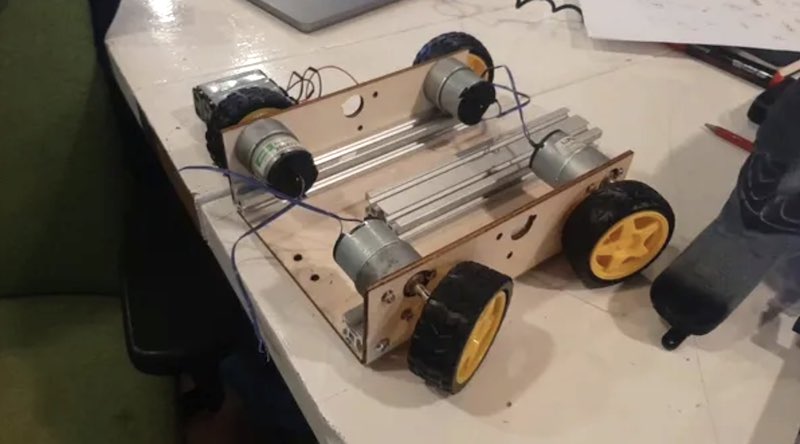
vehicle made with laser cut wood and 20mm profile
Here the quickly written Arduino source can be found. In the Arduino code the eight positions of the arcade joystick are mapped to four motor velocities and directions. Rotation on the spot works but, as commented upon later, this is not very realistic. In the following video a first perspective is given (with the faux pigon bobbing in view). Camera stabilisation by the iphone12 works remarkably well.
First birds-eye view on Real Urban Pigeons by RUPEV
lessons learned:
We love the simplicity of the mechanism, and after taking it to the streets we find the following concerns/improvements
- going outside with this (or any other contraption) is a sure-fire win in Amsterdam
- pigeon luring / feeding might need more patience and experience
- wired control is a no-go
- we need a bigger robot in order to have a better mass distribution
- we need larger wheels no negotiate the cobblestones
- we need suspension to stabelise pigeon and camera
- pigeon needs to rest on the surface (or at least touch down lightly)
- the ‘pigeon slap’ motion (when the pigeon swiftly moves sideways) is fun (when applied to supervisors (Henk) sitting down) but completely dispels the illusion of a pigeon walking
Spiral 2: omniwheel
In order to avoid the ‘pigeon slap’ - or at least in order to be able to move sideways in such a way that a front-mounted pigeon rotates on the spot - we need a robot base that is holonomic (or does not suffer non-holonomic constraints). A typical two-wheel driven robot (tank driven) or a steering mechanism (like a car, Ackermann principle) are non-holonomic. One of the few mechanisms capable of moving in any direction from any starting position, without adjustment (such as active pivot wheels) is using either omniwheel (linear rollers) or mecanum wheels (45 dg rollers)
We already found that with the fixed box of spiral 1 we need some sort of suspension to make sure all driven wheels are (always) on the ground. We find this example vehicle as inspiration. So let’s fab it instead!
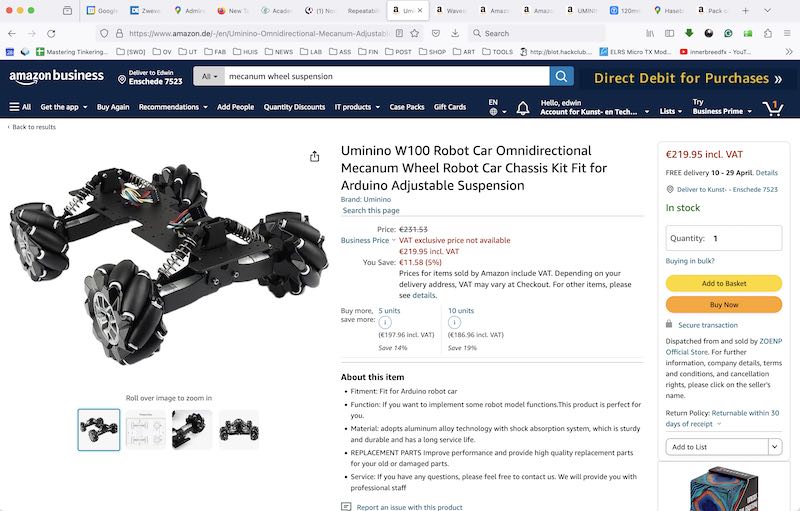
Example vehicle on amazon
We decide to use a small stack of 200mm x 20x20mm extrusion profile that was left by a previous machine-building group. As inspiration we also find this mecanum wheel on thingiverse which might be apt for production (although a lot of work).
mecanum wheel
Mecanum wheel can be bought online (96mm with 6mm hubs, similar to this but it might be more interesting to design our own. The thingiverse design needs 24 693ZZ ball-bearings per wheel. (Even at the lowest prices (4.79 ex VAT for 10) this will set us back 50.-) We decide not to use them and re-design the wheel in such a way that small nylon bushings can be used as bearings. We put parts to print and start on the frame.

wheel design from thingiverse

wheel sliced in cura
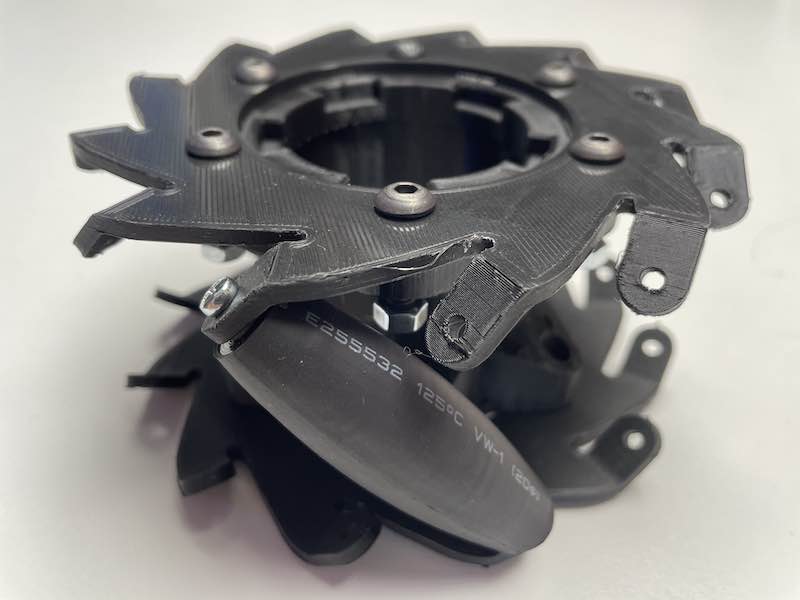
mecanum wheel
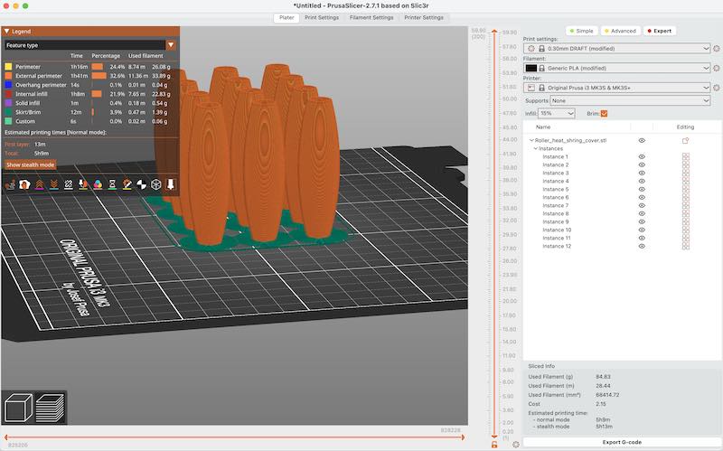
rollers sliced in prusa slicer
We decide to re-design the wheel and rollers so the bearings can be replaced by small nylong bushings. The wheel hub needs to be re-designed to fit our motor shafts. We use a variant with heat-shrink tubing as ’tires’. Eventually we’ll require 48 rollers (adapted design) with heat shrink tubing, 96 bushes, 8 sideplates and 4 custom hubs. + 96 screws and 4 metres of heat-shrink tubing.
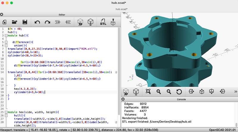
wheel hub re-design in OpenSCAD
Here is the OpenSCAD script and the original thingiverse STL file it is adjusting:
Also a number of bearings / bushes are designed using OpenSCAD:
Printing and assembling the rollers has been postponed after re-prioritising all project tasks mid-way. Also the fact that printing 12 rollers on one bed was (even for our trusty Ultimakers) sometimens non-trivial:
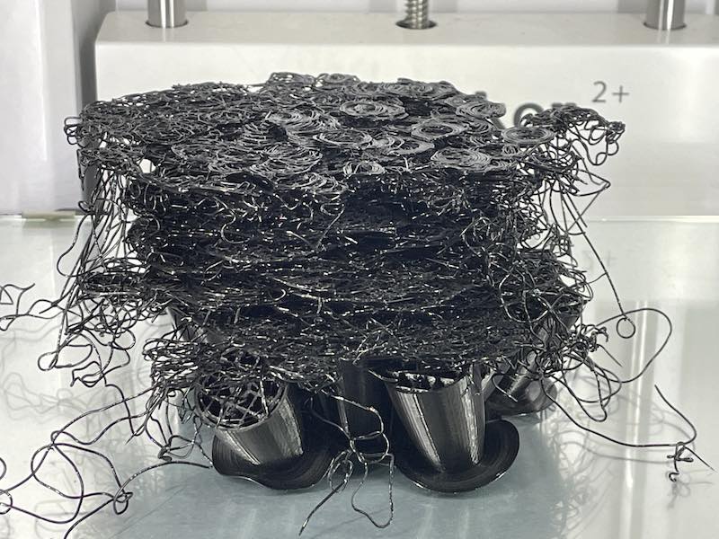
loose brim mid-way
frame
For the frame we chose to use 20x20 profile cut in sections of 80mm This results in a frame size of 320x320 mm which fits our specifications. We design and construct 4 wheel arms housing the Jameco 12V 1:50 geared motors and make them hinge using 608 bearings (that happen to be available).
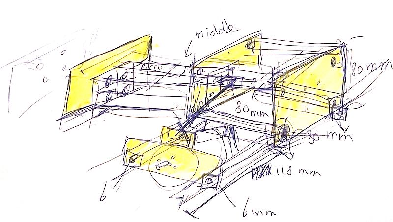
Drawing of the mechanism as discussed with (and drawn by) Vera
building the frame out of (mostly) 80mm segments
The 20x20 profile can be threaded internally with M6, so for the inside of the bearings we cannot use standard 5mm bearings or wheels. The 608 bearings need a small adapter piece inside:
$fn = 40;
difference(){
    union(){
        cylinder(d=12,h=1);
        cylinder(d=8,h=8);
    }
    translate([0,0,-0.01])cylinder(d=6.2,h=30);
}
Vera designs the side plate (4 identical) and the motor mount plate (4 identical) on the wheel arm. After a first try in cardboard the pieces are cut in 6mm acrylic.

Parts for the frame laid out
Next day we move to my (home)lab in Enschede and continue on the robot frame and control hardware. I happen to have a set of 96mm mecanum wheels salvaged from a students project. With these wheels in place the frame appears way too wide, so we decide to shorten the wheel arms from 12 to 8 cm.

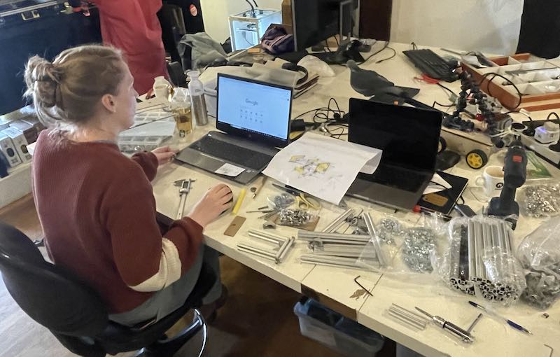
Work session in home lab in Enschede
We re-use a number of 3D printed 20x20 wheel brackets from a previous design as hinge-points for the suspension springs. Instead of buying RC-model spring-dampers, we choose to try and design our own on the 3D printer.
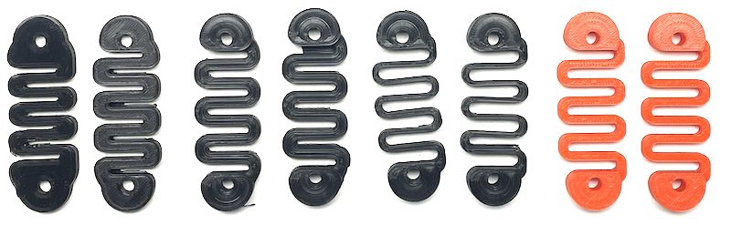
Iteration of springs, in the end we used them all to adjust stiffness of the suspension on the fly
Even using PLA this works surprisingly well. The current springs are in the third iteration.
pigeon mechanism
The four-bar linkage excentric mechanism is designed by Joe and Leo. During the first weekend some of the test versions are cut using Lightburn on the Genmitsu L8 40W laser in my home lab:
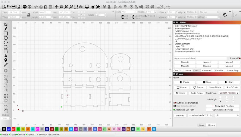
Frame design in lightburn ready to cut
Leo showing a first pigeon transmission system
motor driver
For the control I would like to keep using the Pico (and improve skills / expand libraries). In the box with expansion boards and test systems I found an unused Waveshare Pico Motor Control (using PCA9685 and 2 2-channel drivers, 4 motors in total) information through this link. Although the Waveshare site claims to have sources in C, all I can find is a python sketch.

Pico Motor control board by Waveshare
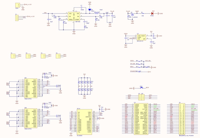
Pico Motor control board schematic
class MotorDriver():
    def __init__(self, debug=False):
        self.debug = debug
        self.pwm = PCA9685()
        self.pwm.setPWMFreq(50)
        self.MotorPin = ['MA', 0,1,2, 'MB',3,4,5, 'MC',6,7,8, 'MD',9,10,11]
        self.MotorDir = ['forward', 0,1, 'backward',1,0]

    def MotorRun(self, motor, mdir, speed, runtime):
        if speed > 100:
            return

        mPin = self.MotorPin.index(motor)
        mDir = self.MotorDir.index(mdir)

        if (self.debug):
            print("set PWM PIN %d, speed %d" %(self.MotorPin[mPin+1], speed))
            print("set pin A %d , dir %d" %(self.MotorPin[mPin+2], self.MotorDir[mDir+1]))
            print("set pin b %d , dir %d" %(self.MotorPin[mPin+3], self.MotorDir[mDir+2]))

        self.pwm.setServoPulse(self.MotorPin[mPin+1], speed)
        self.pwm.setLevel(self.MotorPin[mPin+2], self.MotorDir[mDir+1])
        self.pwm.setLevel(self.MotorPin[mPin+3], self.MotorDir[mDir+2])

        time.sleep(runtime)
        self.pwm.setServoPulse(self.MotorPin[mPin+1], 0)
        self.pwm.setLevel(self.MotorPin[mPin+2], 0)
        self.pwm.setLevel(self.MotorPin[mPin+3], 0)
So, from the PCA9685, every thme 3 channels are used for one motor: the first as PWM velocity input, the other two at 0 or 4095 (digital 0 or 1) to set direction (braking or coasting)
Again, different pins have been used instead of regular pin 4 and 5, SDA0 and SCL0 - with the following instruction in void setup() this can be changed. On the waveshare pico motor board pins 20 and 21 are used.
  Wire.setSDA(20);
  Wire.setSCL(21);
Subsequently the waveshare board is mounted on the frame using a lasercut 80 x 80 mm sheet of 3mm ply-wood (engraved) for this authentic Fab-Feel :) (and, yes, for once designed in Inkscape, Yay!)
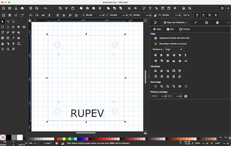
RUPEV board carrier in Inkscape
wireless control
For the PPM signal several libraries have been explored. Only the PPMreader does compile (since it did not contain any direct timer references) for the Pico. However, it does not work, for some reason to do with the interrupt attachement function. Direct attachment in code does however work. As (blunt) solution I used all the library bits step-by-step in one main source file and tidy up. (using PPM-Reader 1.2.0 Dmitry Grigoryev through Arduino library manager - but no longer as library)
PPM signal received from RF receiver and interpreted correctly
For the specific receiver (SPEKTRUM DX 6 channel DSM2) the PPM signal is inverted (as in, high by default). I modified the interrupt to be interrupt on Falling edge. Now the software is able to measure 6 pulses with enough (?) accuracy.
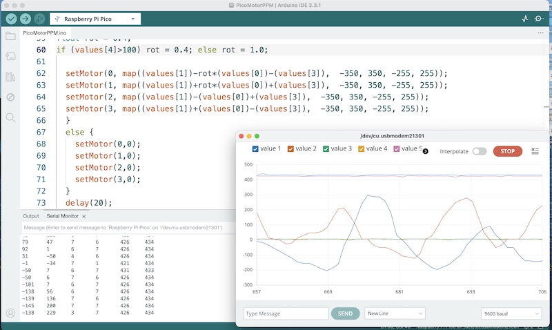
In the code, in order to avoid the pigeon slap, a rotation mode is added which makes the RUPEV robot rotate around the spot where the pigeon’s feet will be located. The ratio in the following code (difference between front two wheels and back two wheels) is set at 0.4.
circular motion results in rotation ratio
The code (for now) is the following:
//////////////////////////////////////////////////////////////////////////////////////////////////////////
// PicoMotorPPM for Pigeon Control (PMPPMPC)
//
// Software for group assignment, FabAcademy, Waag team 2024
//
#include <Wire.h>
// use Adafruit's PCA9685 driver, but this time not for RC servos but plain PWM on the WaveShare H-bridge
#include <Adafruit_PWMServoDriver.h>
Adafruit_PWMServoDriver pwm = Adafruit_PWMServoDriver();
#define DEADZONE 5 // otherwise motors keep humming...
// Initialize a PPMReader on digital pin 3 with 6 expected channels.
byte PPMpin = 3; // the pin for PPM radio input
byte channelAmount = 6;// number of channels on receiver
// and the code starts here:
void setup() {
  Serial.begin(115200);                 // Our Debug Interface
  pinMode(25, OUTPUT);                  // Pico on board LED
  attachInterrupt(PPMpin, ISR, FALLING);// PPM input pin
  Wire.setSDA(20);                      // redirect for WaveShare board pinout
  Wire.setSCL(21);                      // redirect for WaveShare board pinout
  pwm.begin();                          // start the PCA9685
  pwm.setOscillatorFrequency(27000000); // base frequency
  pwm.setPWMFreq(16000);                // check which modes still work. Faster PWM means less noise means more switching loss
  Wire.setClock(400000);                // can be fast
}
void loop() {
  int values [] = {0,0,0,0,0,0};
  for (byte channel = 1; channel <= channelAmount; ++channel) {
    values [channel-1] = (latestValidChannelValue(channel, 1550)-1550); // 1550 is the current center value
    Serial.print(values[channel-1]);
    if (channel < channelAmount) Serial.print('\t');
  }
  Serial.println();
  if(values[2] > -300){   // failsafe on throttle channel
    float rot = 0.4;      // rotation mode (around pigeon center
    if (values[4]>100) rot = 0.4; else rot = 1.0; // else translation
    setMotor(0, map((values[1])-(rot*(values[0]))-(values[3]),  -350, 350, -255, 255));
    setMotor(1, map((values[1])+(rot*(values[0]))+(values[3]),  -350, 350, -255, 255));
    setMotor(2, map((values[1])-(values[0])+(values[3]),  -350, 350, -255, 255));
    setMotor(3, map((values[1])+(values[0])-(values[3]),  -350, 350, -255, 255));
  }
  else {
    setMotor(0,0);
    setMotor(1,0);
    setMotor(2,0);
    setMotor(3,0);
  }
  delay(20);
}
// for the Waveshare PCA9685 the following channel assignment is used
//                MA        MB       MC       MD
int motorpins[] = {0, 1, 2, 3, 4, 5, 6, 7, 8, 9, 10, 11};

void setMotor(int motor, int value) {
  if(value>255) value = 255;
  if(value<-255) value = -255;
  if (value > DEADZONE) {
    pwm.setPWM(motorpins[motor*3], 0, map(value, 0, 255, 0, 4095));
    pwm.setPWM(motorpins[motor*3+1], 0, 4095);
    pwm.setPWM(motorpins[motor*3+2], 0, 0);
  }
  else if (value < -DEADZONE) {
    pwm.setPWM(motorpins[motor*3], 0, map(-value, 0, 255, 0, 4095));
    pwm.setPWM(motorpins[motor*3+1], 0, 0);
    pwm.setPWM(motorpins[motor*3+2], 0, 4095);
  }
  else {
    pwm.setPWM(motorpins[motor*3], 0, 0);
    pwm.setPWM(motorpins[motor*3+1], 0, 0);
    pwm.setPWM(motorpins[motor*3+2], 0, 0);
  }
}
////////////////////////////////////////////////////////////////////////////////////////////////////////
//
// PPMreader code
//
volatile unsigned long microsAtLastPulse = 0;
// A counter variable for determining which channel is being read next
volatile byte pulseCounter = 0;
// Arrays for keeping track of channel values
volatile unsigned rawValues [6];
// The range of a channel's possible values (microseconds)
unsigned minChannelValue = 1000;
unsigned maxChannelValue = 2000;
// The maximum error (in either direction) in channel value with which the channel value is still considered valid
unsigned channelValueMaxError = 10;
// The minimum blanking time (microseconds) after which the frame current is considered to be finished
// Should be bigger than maxChannelValue + channelValueMaxError
unsigned blankTime = 2100;
// The timeout (microseconds) after which the channels which were not updated are considered invalid
unsigned long failsafeTimeout = 200000L; // 200 mS
int rawChannelValue(byte channel) {
  // Check for channel's validity and return the latest raw channel value or 0
  unsigned value = 0;
  if (channel >= 1 && channel <= channelAmount) {
    noInterrupts();
    value = rawValues[channel - 1];
    interrupts();
  }
  return value;
}
int latestValidChannelValue(byte channel, unsigned defaultValue) {
  // Check for channel's validity and return the latest valid channel value or defaultValue.
  unsigned value = defaultValue;
  unsigned long timeout;
  noInterrupts();
  timeout = micros() - microsAtLastPulse;
  interrupts();
  if ((timeout < failsafeTimeout) && (channel >= 1) && (channel <= channelAmount)) {
    noInterrupts();
    value = rawValues[channel - 1];
    interrupts();
    if (value >= minChannelValue - channelValueMaxError && value <= maxChannelValue + channelValueMaxError) {
      value = constrain(value, minChannelValue, maxChannelValue);
    }
    else value = defaultValue;
  }
  return value;
}
void ISR() {
  if (digitalRead(25) == 1) digitalWrite(25, LOW); else digitalWrite(25, HIGH);
  unsigned long previousMicros = microsAtLastPulse;
  microsAtLastPulse = micros();
  unsigned long time = microsAtLastPulse - previousMicros;

  if (time > blankTime) {
    // Blank detected: restart from channel 1
    pulseCounter = 0;
  }
  else {
    // Store times between pulses as channel values
    if (pulseCounter < channelAmount) {
      rawValues[pulseCounter] = time;
      ++pulseCounter;
    }
  }
}
Evemtually the code is expanded with control for the H-bridge and audio module (see below). the full source can be found here:
camera
for the wireless there is an FPV set by Fat Shark available. fat shark teleporter V5 This is a system consisting of a camera with 5.8GHz transmitter and an analog receiver built into a set of goggles. The goggle system also has a separate pal video output.
The camera mount with smartphone seems to be working fine as overhead / 3rd person camera since a modern smartphone has fantastic image stabilisation built in, especially when using an app like black magic. Alternatively a generic action camera (go-pro like) can be mounted.
As head camera I like to get started with the seeed xiao ESP32S3 camera. This camera is extremely small and fits as a breakout board on the Xiao board, also including an SD card slot. Examples for making the camera work through WIFI are available.
I clone Seeed’s repository with git clone https://github.com/limengdu/SeeedStudio-XIAO-ESP32S3-Sense-camera (the camera sources listed on the site do not compile directly because of all dependencies). In Arduino IDE 2.3.1 I have to select PSRAM -> OPI PSRAM (otherwise the serial terminal throws a warning). The amount of terminal feedback for the given example code (the ESP32-CAM-MJPEG2SD example code) is excellent!
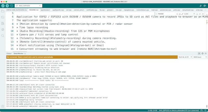
Compiling source for the ESP32S3 in Arduino
When the camera cannot find a WIFI source (which has to be set upon bootup) it will boot up into WIFI AP mode. When connecting to this access point a page is hosted at 192.168.4.1 where configuration settings can be done, as well as camera recording can be started / stopped / played back, etc.

configuring the camera through its hosted browser app at 192.168.4.1
The camera runs very hot, so I mount a small heat sink on the board. This has a beneficial effect: the temperature (which is logged on the hosted page) drops from an average of 70 degrees to 50 degrees.
I solder a small lipo battery socket on the board so it can be run using an interchangeable lipo. Vera designed a very nice fitting leather head-mount cap for the pigeon:
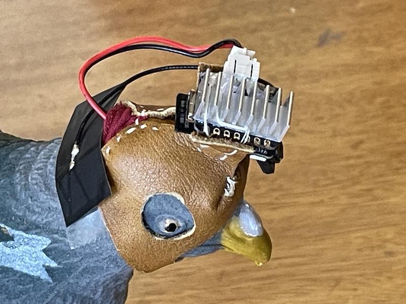
ESP32S3 sense camera on pigeon hood
Spiral 3 - stable pigeon mount (DPSS)
Now the base is driving well, a different challenge needs to be tackled. The faux pigeon in the first prototype (spiral 1) was bouncing along unrealistically. The mechanical pigeon eventually needs:
- a drive shaft with quite bit of torque
- ridgid positioning in front of the vehicle in the X-Y plane
- flexible positioning (spring/damping/suspension) in the Z-plane
The following parts have been designed in OpenSCAD, consisting of three parallel (carbonfibre) rods in a parallellogram. In the center a drive-shaft for the pigeon leg propulsion mechanism is placed, using 11mm x 5mm flange bearings and universal joints. The shaft is also a 5mm carbon fiber rod.
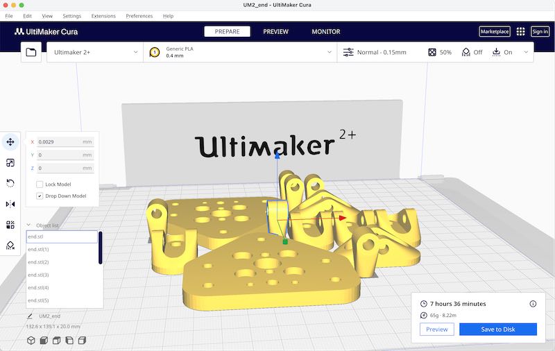
parts for suspension mechanism
$fn = 40;
height = 5;
//hinge();
//end();
//plate();
clamp();
module clamp() {
  difference() {
    union() {
      hull() {
        cylinder(d = 10, h = 20);
        translate([-8, -5, 10])rotate([-90, 0, 0])cylinder(d = 8, h = 10);
      }
      translate([0, -6.5, 5])rotate([-90, 0, 0])cylinder(d = 5, h = 13);
      translate([0, -6.5, 15])rotate([-90, 0, 0])cylinder(d = 5, h = 13);
    }
    cylinder(d = 5, h = 22);
    translate([-8, -6, 10])rotate([-90, 0, 0])cylinder(d = 3, h = 12);
    translate([-8, -3, 10])rotate([-90, 45, 0])cutout();
    translate([-8, -3, 10])rotate([-90, -45, 0])cutout();
    translate([0, -6.5, 5])rotate([-90, 0, 0])cylinder(d = 2.5, h = 13);
    translate([0, -6.5, 15])rotate([-90, 0, 0])cylinder(d = 2.5, h = 13);
  }
}

module cutout() {
  union() {
    cylinder(d = 10, h = 6);
    translate([-10, -5, 0])cube([10, 10, 6]);
  }
}
module plate() {
  difference() {
    union() {
      hull() {
        translate([0, 0, 0])cylinder(d = 20, h = height);
        translate([0, 20, 0])cylinder(d = 20, h = height);

        translate([50, 0, 0])cylinder(d = 20, h = height);
        translate([50, 20, 0])cylinder(d = 20, h = height);

        translate([25, 40, 0])cylinder(d = 20, h = height);
        translate([25, 60, 0])cylinder(d = 20, h = height);
      }


    }
    translate([0, 0, -0.01])cylinder(d = 4.5, h = height + 0.02);
    translate([0, 20, -0.010])cylinder(d = 4.5, h = height + 0.02);
    translate([50, 0, -0.01])cylinder(d = 4.5, h = height + 0.02);
    translate([50, 20, -0.010])cylinder(d = 4.5, h = height + 0.02);
    translate([25, 40, -0.01])cylinder(d = 4.5, h = height + 0.02);
    translate([25, 60, -0.010])cylinder(d = 4.5, h = height + 0.02);
    // mounting holes
    translate([15, 10, 0])cylinder(d = 5, h = height + 0.01);
    translate([35, 10, 0])cylinder(d = 5, h = height + 0.01);
    translate([15, 30, 0])cylinder(d = 5, h = height + 0.01);
    translate([35, 30, 0])cylinder(d = 5, h = height + 0.01);
    translate([15, 10, 2])cylinder(d = 10, h = height + 0.01);
    translate([35, 10, 2])cylinder(d = 10, h = height + 0.01);
    translate([15, 30, 2])cylinder(d = 10, h = height + 0.01);
    translate([35, 30, 2])cylinder(d = 10, h = height + 0.01);
    // central shaft bearing
    translate([25, 20, 0])cylinder(d = 11, h = height + 0.01);
    // toy motor
    translate([25 + 17.5 / 2, -1, 0])cylinder(d = 3, h = height + 0.01);
    translate([25 - 17.5 / 2, -1, 0])cylinder(d = 3, h = height + 0.01);
    translate([25, 8, 0])cylinder(d = 4.3, h = height + 0.01);
    translate([25, 33, 0])cylinder(d = 3, h = height + 0.01);
    // profile
    translate([25, 0, 0])cylinder(d = 5, h = height + 0.01);

  }
}

module hinge() {
  difference() {
    hull() {
      cylinder(d = 20, h = 3);
      translate([20, 0, 0])cylinder(d = 20, h = 3);
      translate([10, -10, 12])rotate([-90, 0, 0])cylinder(d = 10, h = 20);
    }

    cylinder(d = 5.5, h = 20);
    translate([20, 0, 0])cylinder(d = 5.5, h = 20);
    hull() {
      translate([0, 0, 3])cylinder(d = 10, h = 20);
      translate([20, 0, 3])cylinder(d = 10, h = 20);
    }
    translate([10, -10, 12])rotate([-90, 0, 0])cylinder(d = 4.5, h = 20);
  }
}

module end() {
  difference() {
    hull() {
      cylinder(d = 10, h = 9.5);
      translate([0, 0, 4.75])rotate([0, 90, 0])cylinder(d = 8, h = 15);
    }
    cylinder(d = 5, h = 10);
    translate([4, 0, 4.75])rotate([0, 90, 0])cylinder(d = 5, h = 15);
  }
}
The universal joints needed for the pigen drive shaft have been ordered, but will sadly very likely not arrive in time. So the following quick design file has been drafted for a unversal joint (to be properly parametrised later)
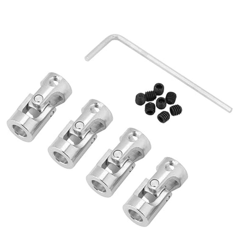
Selection of universal joints that can be ordered

design in OpenSCAD
$fn = 40;
// this is not a proper drawing yet, but it should be a working universal joint for 5 mm shaft
base();
translate([0,0,25])rotate([0,180,90])base();
translate([0,0,12.5-5.3/2])connector();
// the parts:
module base() {
  difference() {
    intersection() {
      union() {
        cylinder(d = 10, h = 7.5);
        translate([-5, -2.5, 0])cube([10, 5, 12.5]);
        translate([-5, 0, 12.5])rotate([0, 90, 0])cylinder(d = 5, h = 10);
      }
      cylinder(d = 10, h = 30);
    }
    cylinder(d = 5, h = 30);
    translate([-2.7, -5, 7.5])cube([5.4, 20, 20]);
    translate([-5, -5, 7.5])rotate([0, 90, 0])cylinder(d = 5, h = 10);
    translate([-5, 5, 7.5])rotate([0, 90, 0])cylinder(d = 5, h = 10);
    translate([-5, 0, 12.5])rotate([0, 90, 0])cylinder(d = 2, h = 10);
    translate([-5, 0, 3])rotate([0, 90, 0])cylinder(d = 2.5, h = 10);
  }
}
module connector() {
  difference() {
    hull() {
      cylinder(d = 5.3, h = 5.3);
      translate([-5.3 / 2, 0, 5.3 / 2])rotate([0, 90, 0])cylinder(d = 5.3, h = 5.3);
      translate([0, 5.3 / 2, 5.3 / 2])rotate([90, 0, 0])cylinder(d = 5.3, h = 5.3);
    }
    translate([-5.3 / 2, 0, 5.3 / 2])rotate([0, 90, 0])cylinder(d = 1.6, h = 5.3);
    translate([0, 5.3 / 2, 5.3 / 2])rotate([90, 0, 0])cylinder(d = 1.6, h = 5.3);
  }
}

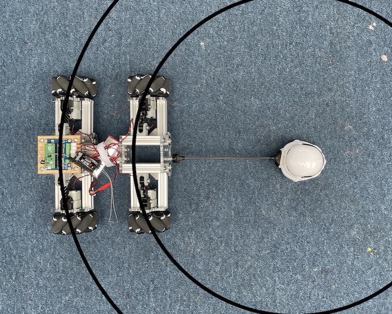
Assembly of the dpss system
DPSS with rotating drive shaft and unversal joints
Furthermore a small suspension bracket has been designed to fit on the three stabilsation rods (5mm carbon fiber rod) which can be changed in position in order to adjust the spring tension:

Suspension bracket in OpenSCAD
motor drive
For the motor an L911S H-bridge driver has been used. This board simply takes two inputs (left, right) per motor. It can be used very well with sign- magnitude PWM in code.
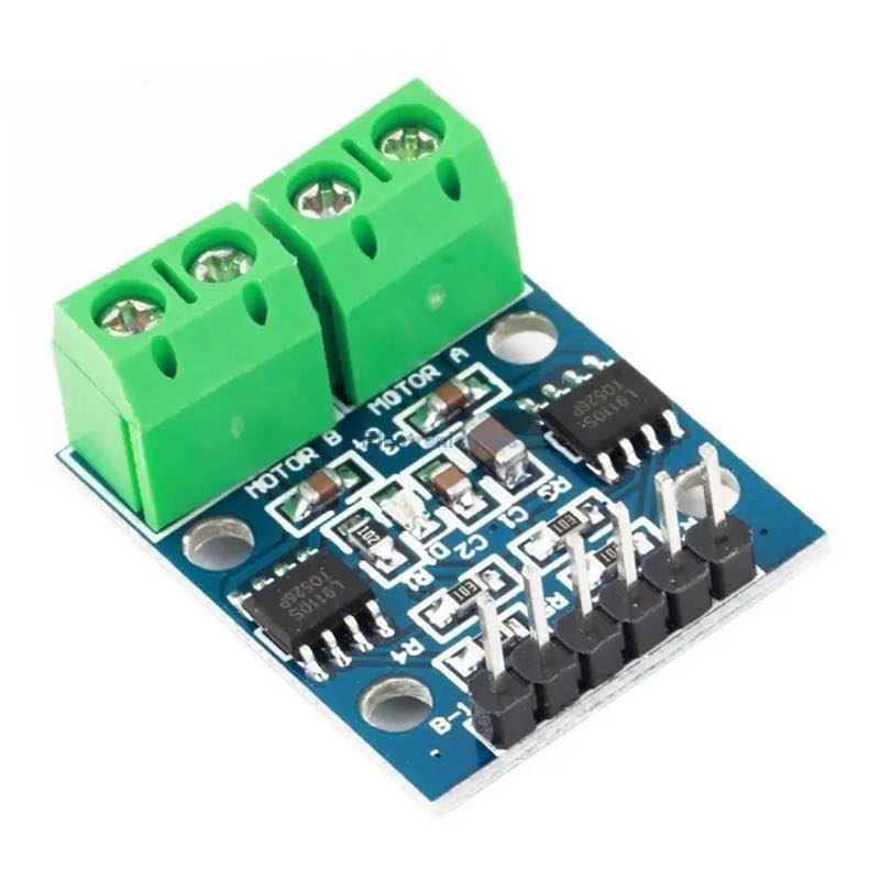
L9110S dual H-bridge
Schematic for the L9110S module
audio player
For the audio A dfrobot mp3 player pro has been used.
A number of pigeon samples Joe selected have been converted using audacity in order to increase volume (normalisation) in some sections:

editing pigeon sound in audacity
The following three sound samples have been integrated in the pigeon player:
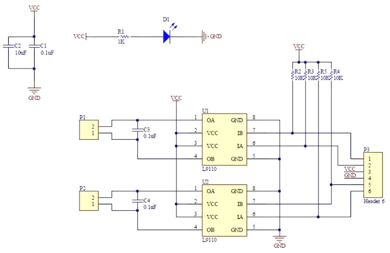
connection board
Vera designed a connection board to add a relay board, audio player and H-bridge driver to the Waveshare Pico board. The following schematic describes the connectivity:
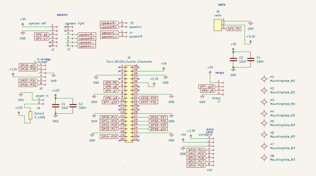
Schematic drawing for the connection board
On this board the following connections were used:
- Motor bridge on GP18 and GP19, GP26 and GP27
- Audio board on GP4 (RX) and GP5 (TX)
- PPM (radio) connector on GP3
- Relay board on GP6 and GP7
- IO expansion (more IO pins) GP10-GP14 on a separate socket
Overall the board worked well, be it for the fact that the H-bridge had been mounted on the wrong side of the board. This in return caused one of the H-bridges to blow out during measuring - eventually leading to both of them failing. For the final demo run we decided to wire up the Pigeon motor in parallel to one of the front drive wheels, so it would turn in sync with the motion of the platform. This worked quite well actually. (so might have been our first choice, saving some hassle. The rotation speed of pigeon feet could however not be adjusted to the forward speed, causing the pigeon to ‘airwalk’
pigeon shell
One great ’nice to have’ features was a transparent pigeon case in order to show the pigeon internals, much like the pictures online showing how a robot pigeon is wired up. I used the Mayku vacuum former to create a few copies of one of the pigeon’s sides

Mayku vacuum formed pigeon half
Eventually in the last minutes before the video shooting takes place the transparent casing is dropped (kill your darlings) in favour of a uniform pigeon casing (without magnetic connection)
Last (frantic) preparations before the shoot
Next, we hit the streets and explore the realm from birds-eye-perspective.
Real Urben Pigeon in Action
So, this is what robot pigeons see…
Real Urban Pigeon Eye View
Eventually we had to add a quick counterweight at the back of the PuppetMaster vehicle to compensate for all the pigeon’s weight. We made quick use of materials at hand. So, eventually we DID use a stepper motor for our machine week project:
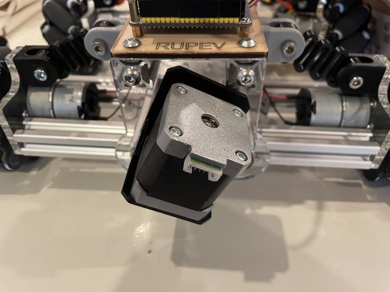
Stepper motor bringing up (down) the rear...
Group process
Throughout the entire scope of the project (two weeks) we kept a very-hot hotline on Mattermost. During the live sessions we kept track of tasks using whiteboard - and quick meetups during lunch. We tried to work as group together as much as possible (although not always possible schedule wise).
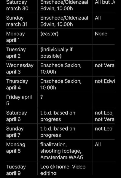
meetup schedule
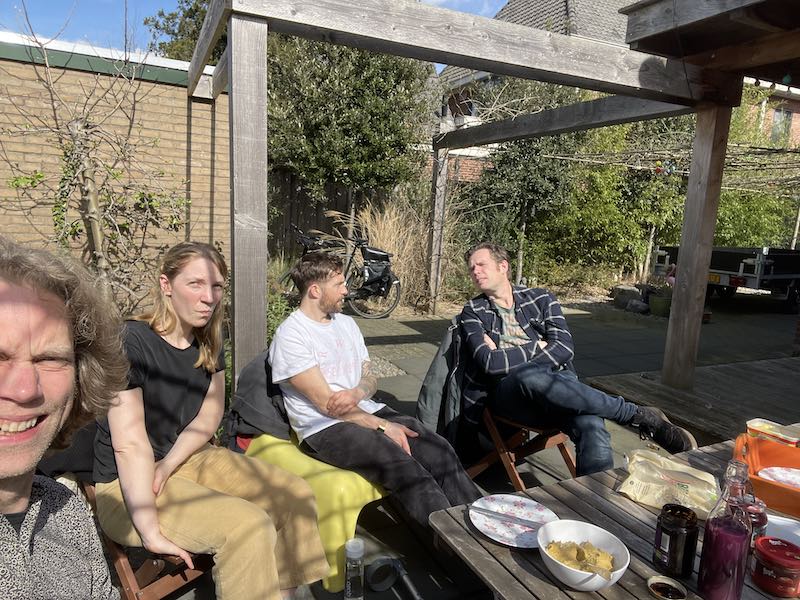
(lunch) meeting in Enschede
Overall we worked two days in FabLab Saxion together, two days at Waag and two days at my (home)lab in Enschede. Most of the tasks got distributed and re-checked during these sessions. We stuck with the priority list drawn up on the first day at Waag (see Leo’s documentation). This meant that on the last day some of our darlings had to be killed because we had a strict (daylight) limit for shooting the final video with Pigeons. Eventually the killed darlings were:
- bobbing head (mechanism did not work)
- separate H-bridge control for pigeaon drive (fried H-Bridge)
- custom 3D printed omniwheels. We did manage to test a pair but could not plan to use them before the final video
- night vision Rasberry Pi camera (we had the ESP32S3 sense head mounted camera instead)
- wireless camera with FPV goggles (did not use them, no far remote control done)
- transparent pigeon side. I did vacuform a half-pigeon, but sadly we could not mount it in time. Looks stunning though…
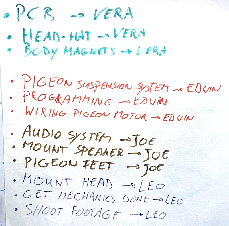
Whiteboard during Enschede sessions
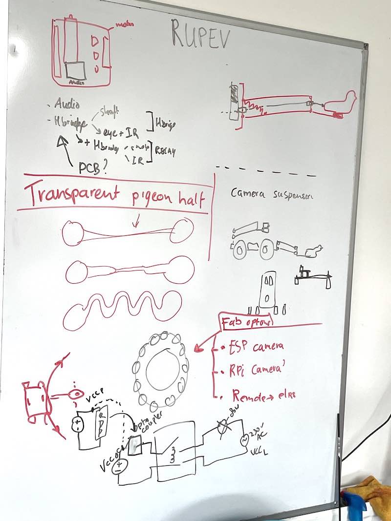
whiteboard for the final day
learning outcomes
- Work and communicate effectively as a team
- Design, plan and build a machine
- Analyse and solve technical problems
- Recognise opportunities for improvements in the design
evaluation checklist
- [-] Documented the machine building process to the group page
- Documented your individual contribution to this project on your own website
- [-] Linked to the group page from your individual page as well as from group page to your individual pages
- Shown how your team planned, allocated tasks and executed the project (Group page)
- Described problems and how the team solved them (Group page)
- Listed possible improvements for this project (Group page)
- Included your design files (Group page)
- You need to present your machine globally and/or include an aprox. 1 min video (1920x1080 HTML5 MP4) + slide (1920x1080 PNG) (Group page)
lessons learned, tips and tricks
(or, the most insightful mistakes I made)
Most helpful thought:
- what if we don’t buy it, what could we use instead.
- read the manual, the datasheet, whatever. Read it Well
- 2.4 GHz DSMX control is very stable and solid. I expected more problems with interfacing PPM signals (as they kind-of represent analogue signals) but this bit eventually worked well
- Use logic analyser and scope more often (!). Especially debugging the PPM radio encoding and writing the code to work with the waveshare motordriver board it was very helpful to keep taps on all signals by using oscilloscope (realtime PWM signal check) and Saleae logic analyser (communication on board)
- WIFI camera on ESP32S3 is very cute (small), very hot (power hungry) and in the end not very stable or useful image wise. Still, a very nice adition (and all the autonomous recognition features have not been explored yet)
- Check, check and double check everything PCB wise. Orientation of components, pinout, so many mistakes to make….
left for todo
- https://www.youtube.com/watch?v=yIXa-6DRW-Y -> pico + pio examples + debug + vscode..
- make the printed wheels
- play around with Black Magic (Leo’s film app of choice)
reflection
This was a very nice, fun and engaging project. I feel there was a lot of room in the group to shape contributions and to pick up things to do or to learn.
I often quickly resort to buying components at Amazon. This is very helpful, since in my homelab I have a fantastic critical mass / critical mess in terms of available components. However, it was also nice to design-print parts (such as the omniwheels or the universal joints) instead. The springs were also a master stroke. By changing the design and printing a number in different materials we had everything to change suspension stiffness on the fly - which would have been impossible using standard RC-car spring-damper units.