Week 10
Mechanical Design (part 1 of 2)
| group assignments | — |
|---|---|
| Design a machine that includes mechanism + actuation + automation + application | |
| Build the mechanical parts and operate it manually. | |
| Actuate and automate your machine. | |
| Document the group project. |
| individual assignments | — |
|---|---|
| Document your individual contribution |
Some general notes:
From Neil’s lecture
Make the Force loop in your machine as short as possible, the bigger it gets, the less reliable the machine gets.
Aligning tools: kinematic mount coupling, three sloths three balls make a high tolerance positioning
Think about accuracy v.s. precision, both is best and hardest.
resolution = ability to show or produce details smallest increment
accuracy = ability to be correct or exact
precision = ability to be repeating the tasks perfectly
Plastic HDPE machines easily and use rubber for damping and vibration
garolite fabric reinforced machines nice and is stiff and strong
Stiffness: how little it deforms if you push on it
Strength: how much power you can supply without it breaking
High temp parts: Aremco ceramics
Stay away from adhesives because you want to dissemble the machine but you will use a lot off fasteners like nuts and bolts, use locknuts to prevent it from loosening. Rivets to clams two parts more permanently
When designing gears you want to have a single point of contact instead of a surface. Be aware of backlash.
you can use springs for backlash optimization
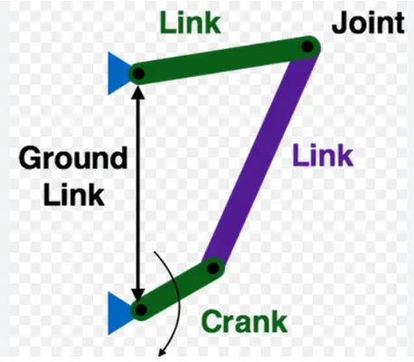
cornell University has a cool library of different kind of linkages
pantograph: scale things up and down
delta bot: linear in to 3d motion
From Saco’s lecture at Waag
- What is a machine?
- It’s a device that user power to perform actions based on certain tasks.
- Don’t forget hydraulics and pneumatics as actuators
Structure the machine building project
- Functional breakdown structure: define the functions
- what does the machine do
- which functions you need for it
- with can be combined/ separate
- product breakdown structure: looks of the machine
- parts of the subsystems
- how can it be build
- Work breakdown structure: divide tasks
- tool: Yworks.com
- who’s responsible for what?
Mechanical principles
- Over constraint, to much constraints. Think about your degree of freedom.
- Which movements needs to be constraint.
- Think of triangles. For example the kinematic coupler.
Movement control:
- sloth followers follow a path
- linkage mechanisms the dimension rations of the linkages will influence the movement it linked to each other
With the site Desmos you can test different linkages
Thursday group work session at Waag
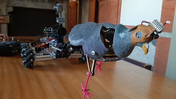
After a good brainstorm about our robot we divide tasks. This is documented on our group page. But in short:
- puppet master robot, omniwheels & programming Edwin
- puppet master robot, PCB, springs (Vera)
- head movement, audio, legs Joe
- mechanical leg movement, body fixture, movie, script and editing Leo
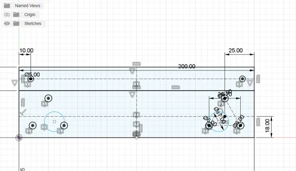
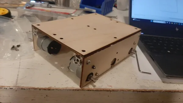
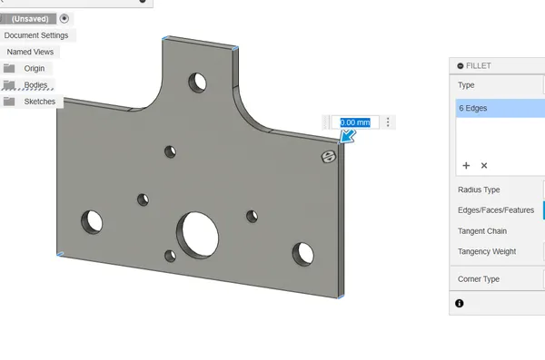
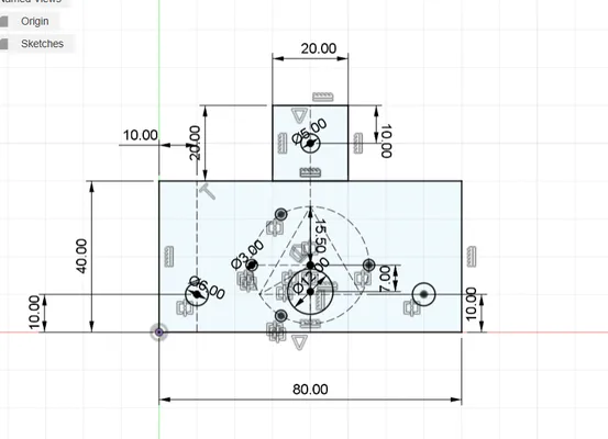
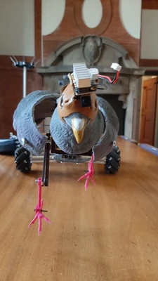
I will be working on the robot car together with Edwin. This will be driving our pigeon around. Today I focus on building the frame for the robot car and for this I will use aluminium frames and also Fusion and the laser cutter. to make a base and a side to assemble the motors for the wheels. I make a drawing of all the holes and cut it using speed: 70 power : 50 for 4 mm soft triplex wood.
- Lasercut files
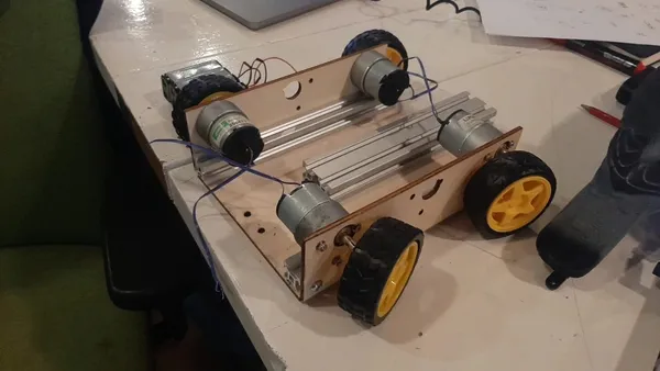
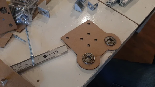
 When I ensemble the car I notice that my wheels don’t line up I made a mistake here. We leave it how it is for now since mirroring the design did not help because the shafts are not centered…
Edwin found a big joystick and programmed it with the wheels to go all four direction. We uses the Arduino shield and Arduino uno to connect the 4 motors.
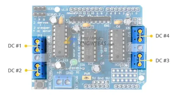
We found out that two motors are now working and we use the power supply to test al the motors. We select 4 that should work but when everything is ensembled it’s still not working. Edwin asks me what screws I used. Turns out if you use long screws for the DC motors you actually block the motor. I did now know this! so we change the screws and used the code Edwin wrote and got the machine to work!
Friday group work session at Waag
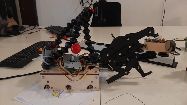
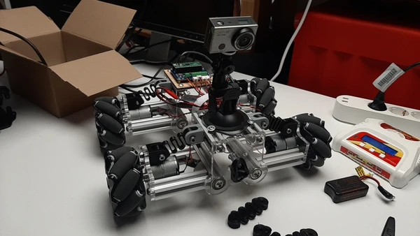
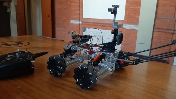
Leo and Joe keep working on the moving mechanism for the head of the pigeon and Edwin and I are developing the second spiral of the robot car. But we start the day with a first testdrive outside withg the car we build yesterday. Once everything is mounted on the car and we use a phone to make the first footage of our project in the documentary perspective. The car is moving a bit wobbly and the pigeon is moving a lot to. Alse the pigeon is moving as if it’s a tank. So for the rotation movement the pigeon shoiuld be the center instead od the robotcar. Edwin found this sample of a robot car with mecanum wheels and suspension top help these problems. However this car costs 230 euros so we decide to make a Fablab version of it, cheap and quick using the aluminium profile and new laser cutter parts to join everything. We will also make hinges. Edwin had this idea in his head and I draw it to help visualising it so I can think about it to. We split tasks and I start with the drawing and developping. Edwin will do the aluminium frame and together we start a few printers to make the mecanum wheels that is an existing design on tinkercad.
For the design process I made sure that everything would fit by measuring and looking at the datasheet of the motor
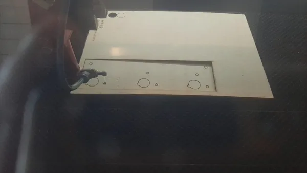
I start cutting the design in cardboard to test the fit. I used speed 70 power 30
After this I cut out thicker acrylics for the robot car using speed 1o power 90.
Saturday group work session at Enschede
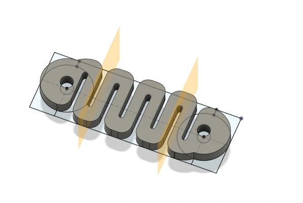
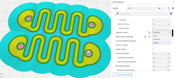
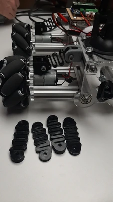
I start the day with Ewin unscrewing the robot car again because the frame is a bit wide we can shorten the aluminium profiles easily. After we did this we continued assembling it again and I worked on the spring mechanism for the suspension. I 3D printed 4 different kinds, changing the thickness and the size to get different kind of suspension. I make 4 versions today and tested them. In the CURA slicing software I used concentric for the base and bottom to get more strength in the part.
 Edwin worked on the remote system for controlling the motors and we tried out the pre bought camera system quickly. It works really nice!
Sunday group session at Enschede
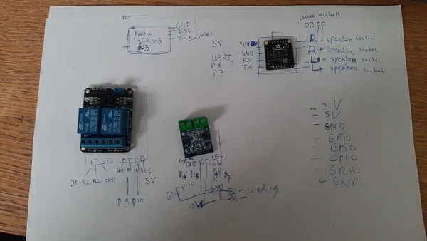
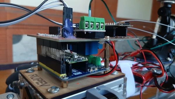
We start the day by testing the new springs they work much better then the previous version. And we started the day with the altered rollers I designed failed over night. They were in the same print and created a real spagetti 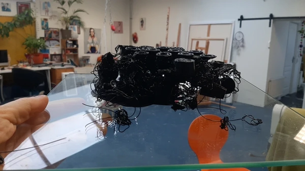 We sat together and discussed the next steps. Since I want to learn more about electronics I will work on the PCB where all the components will come together. For This I start by drawing a schematic by hand for all the VCC’s GND pins and pay attention for each part what it needs.
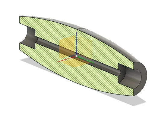
 I discuss some confusing thing with Edwin and Leo and I learned in the process what a Relay looks like if you would cut it in half.
Basically it’s a switch you don’t touch that can switch on and of large power machines or outputs. It uses a LED and a lightsensitive sensor and when you turn on the LED with a PIN output HIGH the sensor notices and is programmed to that close the switch so the current will flow.
I discuss some confusing thing with Edwin and Leo and I learned in the process what a Relay looks like if you would cut it in half.
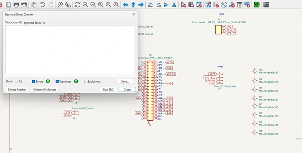
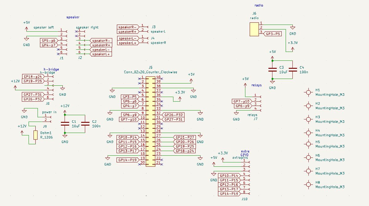
Basically it’s a switch you don’t touch that can switch on and of large power machines or outputs. It uses a LED and a lightsensitive sensor and when you turn on the LED with a PIN output HIGH the sensor notices and is programmed to that close the switch so the current will flow. 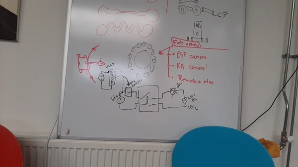 It took me a lot of time because KiCAD but also reading about the parts that we are using and what it needs if all very new for me. I let Edwin check the schematic I now drew in KiCAD. He noticed that I used self-made labels instead of KiCAD power flags for GND and VCC and that this makes my schematic less readable. Also made a huge mistake with the pinouts because the Raspberry pi shield we use for driving the wheels uses pin 20 and 21 so I can’t use them for anything else and I new this and wrote it on the paper but somehow forgot about it when making the schematic in KiCAD so I had to fix these problems. The last issue Edwin pointed out was that I didn’t put capacitors in the design to prevent ‘ruis’ I think it translat as noise from the surrounding and also to help the motor for the pigeon to keep running constantly for example. I add two capacitors near by the Relay and two near the H-bridge both between their power supply and ground. one big one for making sure the power supply won’t flitch and a small one for the noise.
Tuesday work
 Thursday I altered the rollers for the home made macanum wheels based on the tinker cad file again. I already started with it on Sunday but it needed more changes.
- roller version 4 is the version we will use I first altered the part where the spacer will come since we wont use bearings but plastic spacers instead to save some money. After that I altered the depth so the spaces will have it’s top sticking out so everything will turn and later I altered the inside diameter since we don’t have long enough screws we will tap the thread inside and use smaller screws.
Wednesday work
- KiCAD file RUPEV
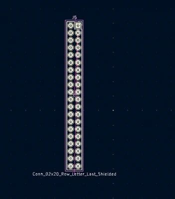
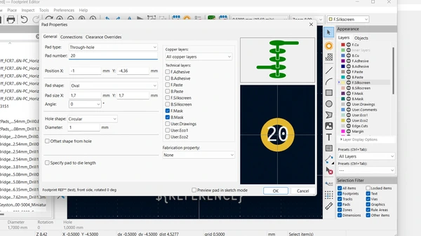
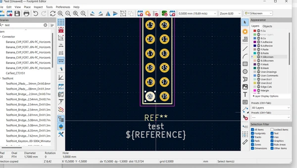
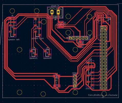
- I made the PCB in the PCB editor in KiCAD and my first issue was that there is not a footprint of a 2 x 20 row pinheaders counting from 1 to 20 and 40 back to 21 to fit the shield.
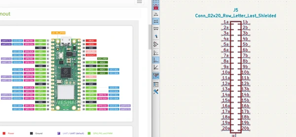 I had to change the footprint to change the numbers into the right order. For this I created a new folder called vera with my first altered footprint:)
Another challenge was to get all the pins on the right side to the left side of the board because there is no space between the pins to cross. I end up using only one 0 ohm bridge to wire everything.
I used 0.8 for all the power traces and 0.4 for the pin traces. It took me a lot of tries to get it right.
I was struggling with the modules and spaces between the pins and holes.
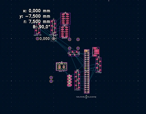 The measure function doesn’t work so well for me.
 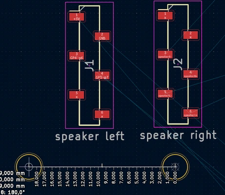 Leo and Edwin gave me a tip to use the grid and put it to the size of the pins so 2.54 because fabricators design on grids. This helped a lot for the DF robots MP3 player module because I needed two sets of pins to go on the board. But for the holes it is less helpful.
I then had the idea to make a copy of the parts because online you can’t find images with the actual real size of the part. I imported the copy and used it to align the holes.
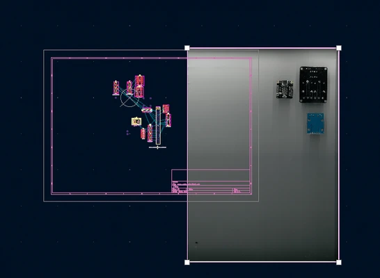
I make a box and scaled a picture I found online to it’s real size to make the backdrop of the driver as a last step and created some space to match the holes on my PCB.
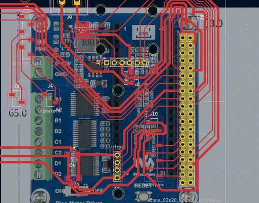
Finished the design! :)
Thursday work at Fablab Saxion Enschede
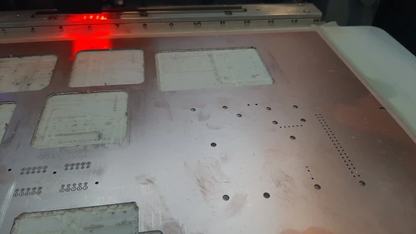
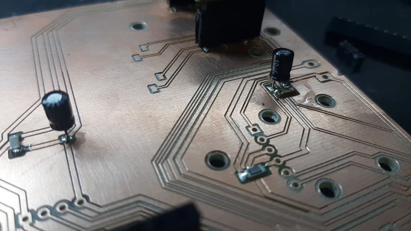
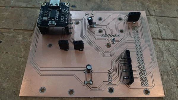
- Today I worked with Leo, I start with milling the PCB design on the LPKF S63 machine at Saxion. This one is super fancy it changes it’s milling bits automatically and you can send all the files as one job. The bed has a vacuum making it easy to get a flat surface. So the making process was easy breezy.
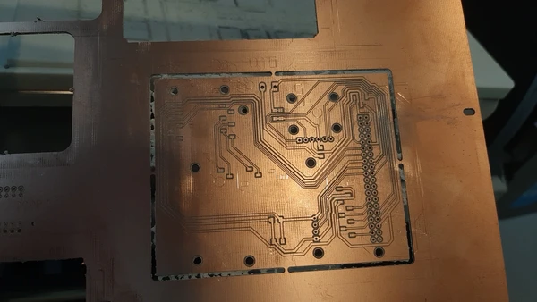
- I continued with the soldering and notices that the big capacitors are not SMD to I should have made it trough hole, but I did not, so I improvised and got it soldered on the board by cutting the legs of the component.
- Next thing is I need to mirror the pins of the relays and H-bridge because I need to put them on the back of the PCB to same some space. For this I first need to get the pins out. Leo and I discus a but and I start with sucking the tin away with the tool and then gently turning the pin. (pin by pin, I broke the black plastic in pieces to get rid of it before I started). I was very content with myself and how it’s going until I noticed a small thickness In a pin that the others didn’t have I take a closer took and see that the via come of with it.
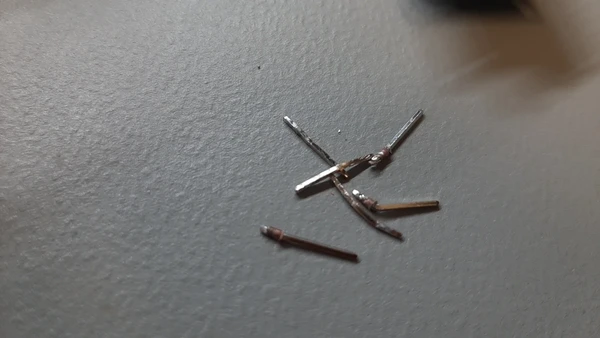 I look at the H bridge underneath the microscope and see it’s missing it’s coper now so I can’t solder a new pin on it… I broke the part. I don’t want to break more so asked Leo’s advise. We used a hot air gun for the relays and on LED got loose in the process but we could fix this so that went ok.
 - For the SMD sockets I used though hole and bend them using plyers because we didn’t have SMD.
- I check all the connections with a mustimeter and make sure I don’t have short cuts. Everything seems fine.
Time flies, Saxion closes at 18.00 so I help Leo with the moving mechanism. I put screw thread inside the 3D printed rollers and make sure to pack everything since it’s coming home with me.
Weekend
In the weekend I worked on the pigeons hood to mount the camera on top of. I had some leather laying around and first made a test with fabric before cutting the leather hood.
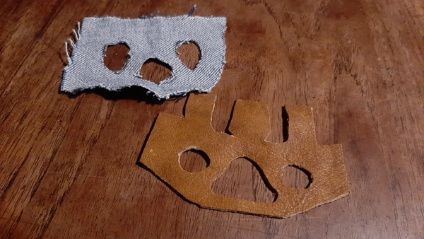
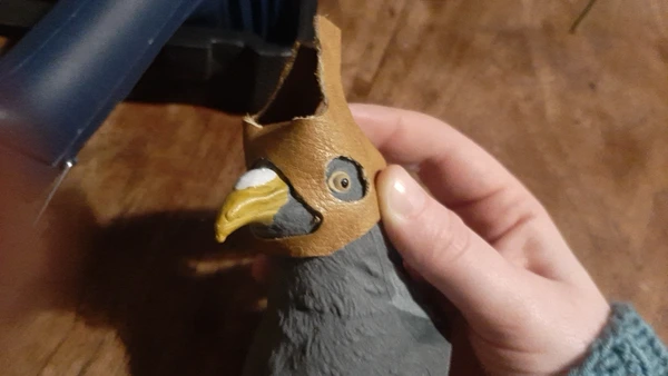 I hand sew some part together and It looks cute. I also worked on the mecanum wheels and use my hot air gun to for the heat shrink tubing to go around the rollers.
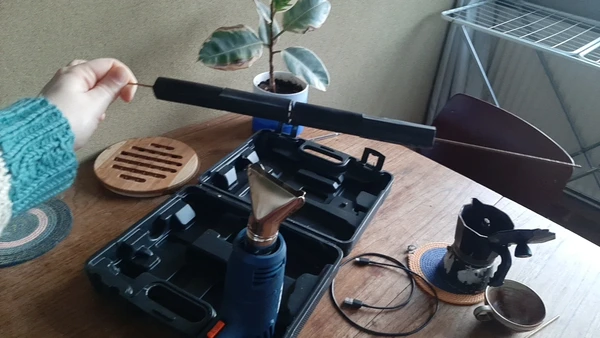 The bigger ones are a struggle. I found out putting a peace of metal thread through the roller and turning it fast above the hot air worked best for me.
Monday at Waag
 This morning we start by dividing tasks so we can finish RUPEV today. My to do list is as following:
Finnish PCB, solder H-bridge relay and raspberry Pico shield
make the body of the pigeon snap together with the magnets
mount the camera and heatsink on the pigeon hood
I soldered the last bits for the PCB and searched for a way to connect the PCB to the Pico shield. Henk helped me and we found these very long pins. Getting the board on and of was a pain that both I and Edwin had to endure often but it worked. We tested all the different modules and had a problem with the h-bridge. Somewhere in the process I convinced myself this components should go on the back of the PCB same as the relay. But in my drawing I put it on top, I didn’t double check and it started to fail when Edwin tested the motor for the pigeon’s movement. When he measured the pinouts one h-bridge got smoky. We double checked the pinouts and I realised my mistake. Feel a bit sad about it but now we know. We try to fix it but didn’t get it to work. We used one of the motors of the wheel to also power the motor for the movement of the pigeon and this was a quick fix of the problem. The PCB it self worked great and did it’s job.
I struggled a bit with the body magnets since the leg movement was not finished I couldn’t test it is would fit. The glue was not strong enough for the magnets. When we put everything together we choose to use screws to fasten the head.
I use thread and a needle to mount the pigeon’s head I found a silicon rubbery like button that I could use to mount everything on top of. And used the leather to put it in place. It looked really funny and did it’s job.
Together we put everything together and used duck tape, glue, wire to quickly fix all it’s little flaws it looks absolutely awesome. We try to lure some pigeons outside and shoot our final shots. It’s great to see everything come together after the hard work! :D
reflection
Main things I learned about during this group assignment:
- building a frame fast with aluminum profiles using different kind of pre made connecters and inserting screw thread combined with laser cutting and bearings!
- sizes of things depend very much on it’s surrounding
- need suspension for wheels to function properly outside
- using a grid in KiCAD and also use pictures as a reference -> tip from Michelle: If you press the space bar your relative x,y position (in the bottom bar) will reset to 0,0 which makes it easy to determine the distance between two points.
- introduction to electrical components like a MP3 player, radio, relay and h-bridges
- alter a footprint in KiCAD
- designing springs using the thickness and width as a variable for it’s stiffness
Tips:
- don’t put long screws in DC geared motors it will ruin them
- triple check all your pin-outs try to find a way so you won’t forget important things
- gravity has a huge influence on the motor, the pigeon had a lot of weight especially since it’s hanging on a long stick.
- moving mechanisms take a lot of space more it’s hard to put it inside a small pigeon body
- glue wont hold magnets down
- try to do test runs and put everything together as soon as you possibly can!
I wished there was more time for me to learn about the programming. This is something I want to learn more about however I’m happy to have worked on the PCB desgin because that was something I also wanted to learn about. This two weeks have been super fun and fast past learning for me. It’s great to work in a group and learn from each other.