computer controlled machining
Toolcart design - result of this week
intro
Trouble. I like to make big things, but these big things have been hunting me every move (as in - ‘move houses’ - kinda move). I have made many CNC designed things like cabinets (for my furbies) or ‘cabinets of curiosoity’ (pepper-ghost-video boxes for an innovation festival) and before that furniture (rietveld stools, baby crib (co-sleeper)) and a fair amount of camping kitchens (even the one in my current camper van). So building something big just-for-fun is a bit of a no-go. I have briefly toyed with the idea of making a piano desk or piano shell-case (something to make your digital stage piano look better and more like a real piano) but I already did something similar with the pianomobil - and they are big and a lot of work to store. So instead I opted for designing something terribly useful for the Lab. (I hope) THerefore I ended up making a mobile tool-rack and prototyping cart, modeled after a design shown in the book ‘Make Space’ - linked to Stanford’s D-School.
For this week the group assignment is to:
- Complete your lab’s safety training
- Test runout, alignment, fixturing, speeds, feeds, materials and toolpaths for your machine
- Document your work to the group work page and reflect on your individual page what you learned
and as individual project (as mentioned) Make (design+mill+assemble) something big.
group assignment
milling theory
A short lecture by Saco took us through the basic mechanics of milling once more. Since a mill is a potentially forceful and dangerous machine, it is important to keep an eye out on risks in operating. Avoiding loose clothing, loose hairs etc (things that can get stuck in the mill). Wearing safety goggles is important. Wearing gloves not so advisable (as clumsyness in operation might introduce more risks than the occasional wood splinter)
The milling considered for this week is 2.5 d (which means the Z-axis does multiple passes of the same 2D track). The mechanical cutting motion of a milling bit against wood (or other material) is very high, typically 20-60 m/s. This results in a chip load (chip size or thickness) of 0.1 .. 0.5 mm, with as widht the cutting depth (typically a few mm)
In the milling process you can follow a path in the direction of rotation of your mill (climb) or against the rotation direction of your mill (conventional). Typically climb milling results in smoother edges, conventional milling in a more even cut regarding outrun (‘kerf’). This is important to consider for both cutting and pocketing operations. Also when clearing out a pocket (like with the PCB milling) the step-over is important, typically 0.5 * the milling bit width.
The cutting speed (this 20 .. 60 m/s) depends on the spindle velocity and bit diameter (v_cut = Vspindle(RPM) . D . Pi/60) For example, for an 6mm end mill a typical speed could be 9000 RPM, resulting in a cut velocity of 30 m/s
The feedrate is depending on the desired chip load (thickness, typically 0.1 .. 0.5 mm), the number of flutes (grooves in the milling bit) and spindle speed. (v_feed = t_chip * n_flutes * V_spindle). For a router cutting at 9000 RPM with a 2-flute 5 mm end mill and a desired chip-load of 0.2 mm) the feedrate would be 0.2 * 2 * 9000 = 40 mm/s. THe higher the RPM, the lower the chip load, a higher feedrate will result in a higher chip load.
When the feedrate is to high, you might excert too high forces on your system resulting in heavy vibration, motors skipping steps and bad cuts in general. Also cutting with a feedrate that is too low has the risk of bad cutting: the milling bit might not ‘bite’ enough in the material, a small chip load combined with a high spinning but relatively slow moving router might lead to burning / smoking.
A bad splintering cut can (thus) be the result of a feedrate that is too high (typically) but also a feedrate that is too low, the spindle speed that is too low (or too high), and also on the material properties, the quality of the milling bit, the phases of the moon and what the operator had for breakfast.
Eventually it is good to work with a test piece to check which runout tolerances need to be taken in to account for specific feedrate / spindle velocity settings, especially when aiming for a nice press-fit connection. Then, when press-fit has been aimed for but eventually appears to be unachievable, there is also the option to resort to violence fit. Nice examples for wood joinery on CNC tooling with as little violence as possible are given in the beautiful 50 cnc joints poster, simulation and video series.
preparing CAM file
Next up, as group effort / demonstration a CAM file is prepared in V-carve Pro version 8.0, Waag’s digital tool linked to their shopbot router.

Climbing setting: outer offset, so set negative (i.e. -0.2mm) value

Group instruction design by Saco
As demo V-Carve software (shopbots CAM tool) is shown to draw and prepare a small design. Nothing vector is imported at this time, everything is designed in the software itself. It is also possible to add dog-bones or T-bone shapes on segments where needed. (I put them in OpenSCAD design directly)
V-Carve 8.0 is used, the following steps are shown:
- new file (-> sheet, base material. Set material properties, sizes, thickness
- set the Z-axis zero (already!) - either on bed level or at the top of the material
- draw shapes (or import something vector: dxf, pdf. No SVG (!)). Add dog-bone or t-bone shape where necessary.
- specify operations per shape / selection of shapes:
- drill (for holes, can be circular shapes, preferably tool diameter)
- inside contour / outside contour
- pocketing (specify pattern)
- t-bone or dog-bone fillets can be added for selected lines (when needed)
- check the drawing for duplicate vectors or open vectors (edit-> select all ..)
- for every operation (mill, drill) hit calculate. After anything: hit ‘calculate everything’ again.
An important step is fixing material to the bed. Clamps can be used, but typically, for large milling jobs, the sheet of material is simply screwed to the sacrificial layer with small wood screws. For that reason the first CAM job to execute is to drill holes in the sheet at locations your parts are NOT going to be.
- drill toolpath: mounting holes -> diameter = mill. select circle, start depht, cut depth (2mm) select tool.
- select tool -> edit in other menu (do not change general settings)
- shift -select holes -> calculate
The best strategy here is to make sure this drill-job is a separate file. You don’t want running the risk that the router touches (or drills) these points ever again after screws have been used. Pausing for toolchange might work, but working in separate files helps keeping out human errors.
Now for the other jobs you have to select the right type of operation and the desired orientation (climb or conventional)
- profile toolpath -> inside, outside, climb conventional -> voor climb: negative off-set alowance (0.2 mm)
- order of your jobs is important: think what is going to get loose
- 2d toolpath -> advanced toolpath options -> runout (offset) (0.1..0.3 mm)
- select: tab: 5 mm, 3 mm thickness (standard), 300 mm spacing-> auto generate. -> calculate
You still have to supply some thinking, especially spacing the tabs. It can be done automatically, but tabs in corners of works pieces are hard to remove (see later)
- pass = 0.5 .. 1 * tool diam
- 12000 rpm, feed rate 50 (saco). plunge rate = 20 .. 25 (this is the ‘drilling’ rate into the material)
- pocket milling: 60% stepover, offset or raster. When doing pocketing at 50% stepover you end up with a lawn-mower-pattern with a bit of material (mill bit outer angle sharpness) in between the lanes.
- give unique toolpath names. They end up on a desktop used by everyone. Use your name, work piece and operation type in the title.
- as already mentioned: make drill file apart!
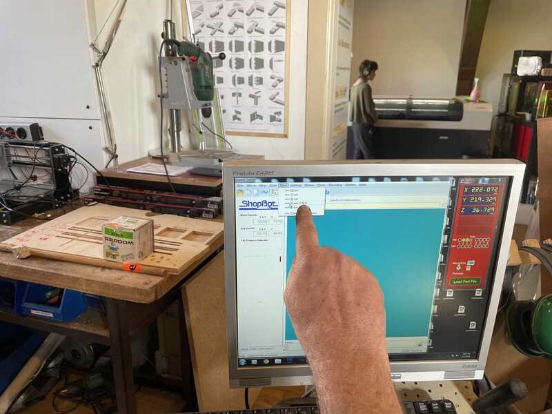
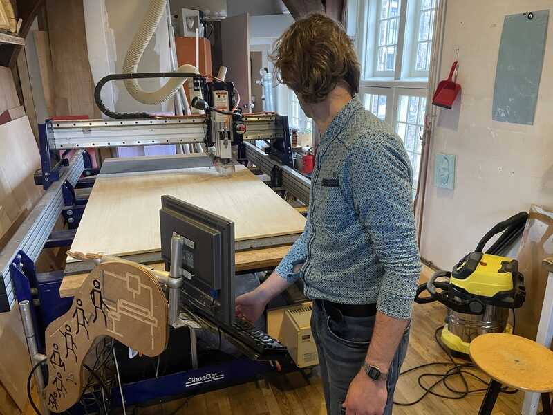
setting up the Shopbot
Waag’s shopbot is a large machine capable of miling 8’ x 4 ’ (2440 x 1220 mm) bed size, using Shopbot’s proprietory control software (and g-code dialect) with V-carve as the main CAM tool. Main safety features are the emergency stop, fire extinguishers - with special attention to the sack of the dust-collector (which has to be thrown out of the window when it starts smoking). The dust collector is housed in a separate cabinet. There are no checks on the machine whether the dust-collector or the mill are turned on (so it is possible to start cutting without the mill running, or without the dust collector turned on). You have to supply the brains in this case :).
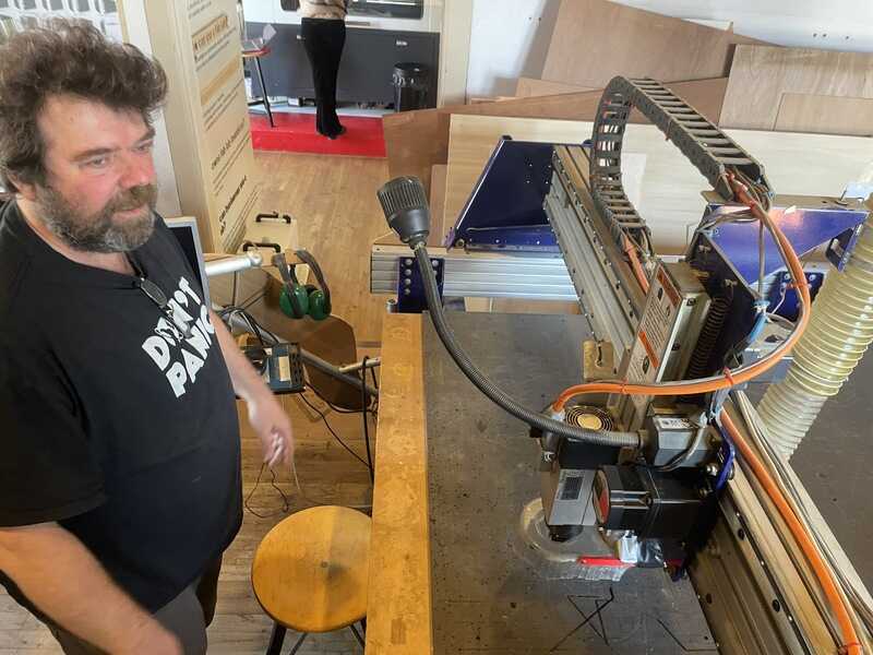
Henk explaining the shopbot
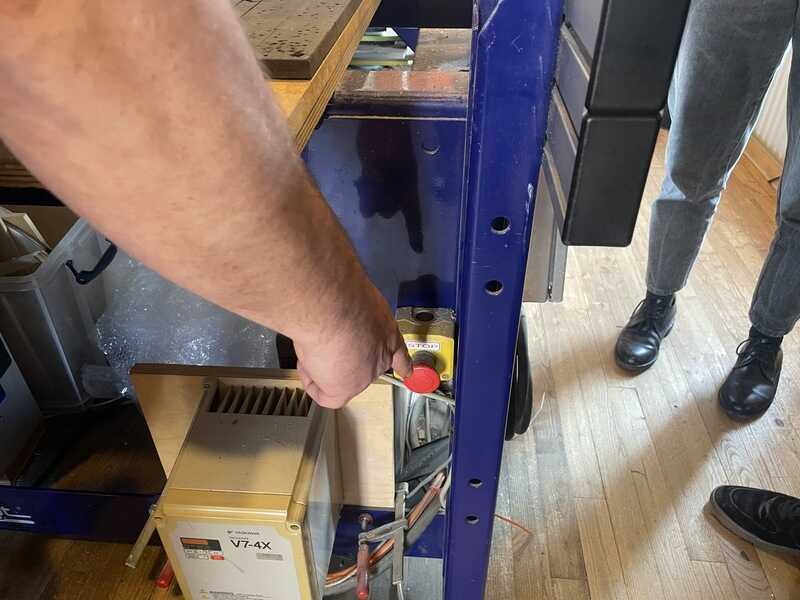
E stop. Only for emergencies. Press this and/when All Is Lost
Don’t use the e-stop unless accidents happening. Better way to stop (and save your work) is to use the spacebar. Remove the dustshoe before you can access the milling bit. The required spanners are linked to the key for turning on (and off) the spindle motor.
Dustshoe needs to be removed to replace the milling bit in the chuck
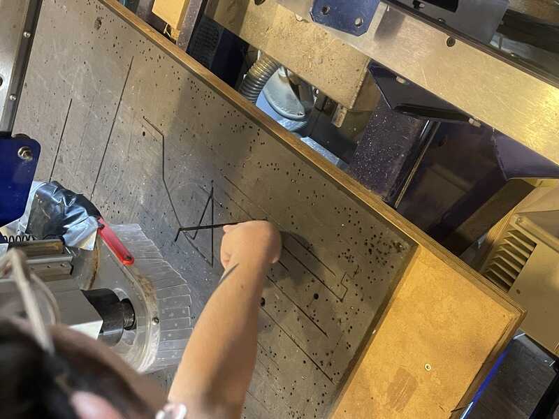
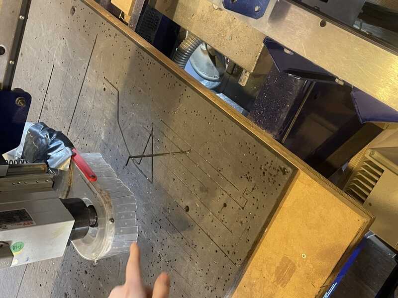
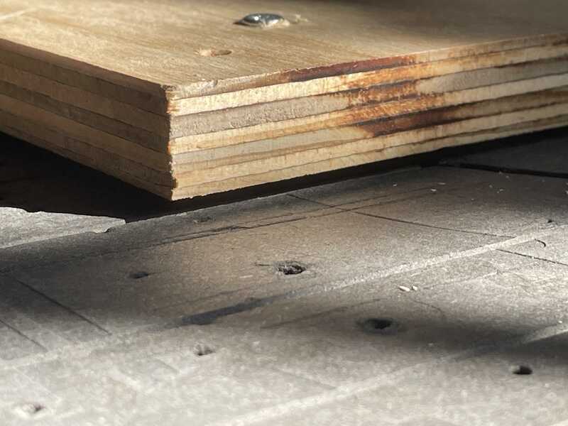
the bed shows its violent history, if this sacrificial layer could talk....

put the bit in the collet after it has been fitted in the chuck (is the ring thingy called chuck?)
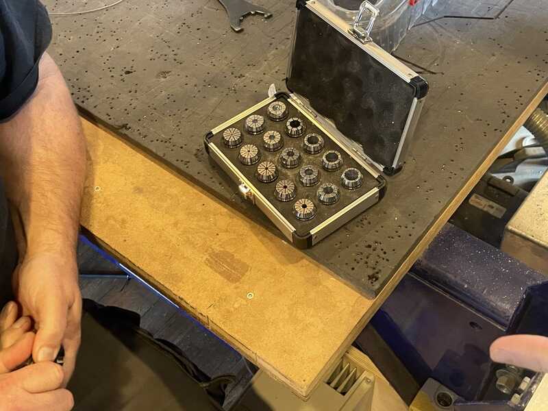
the box of metric collets. The imperial ones are still around somewhere
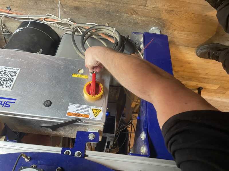
Before software can connect (and you can jog / control the machine) you need to turn on the machine.

the big on-switch. First power on, then start up software
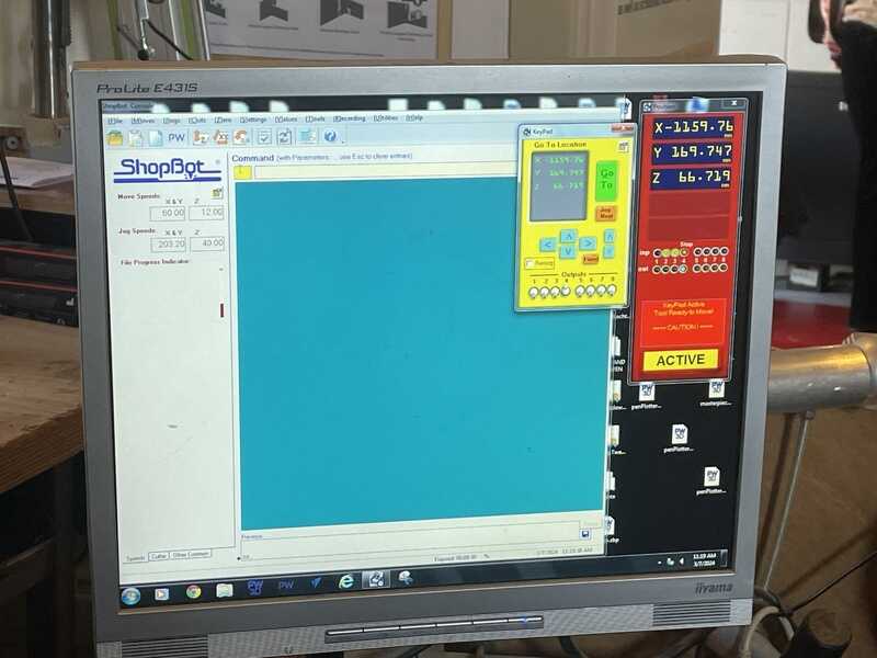
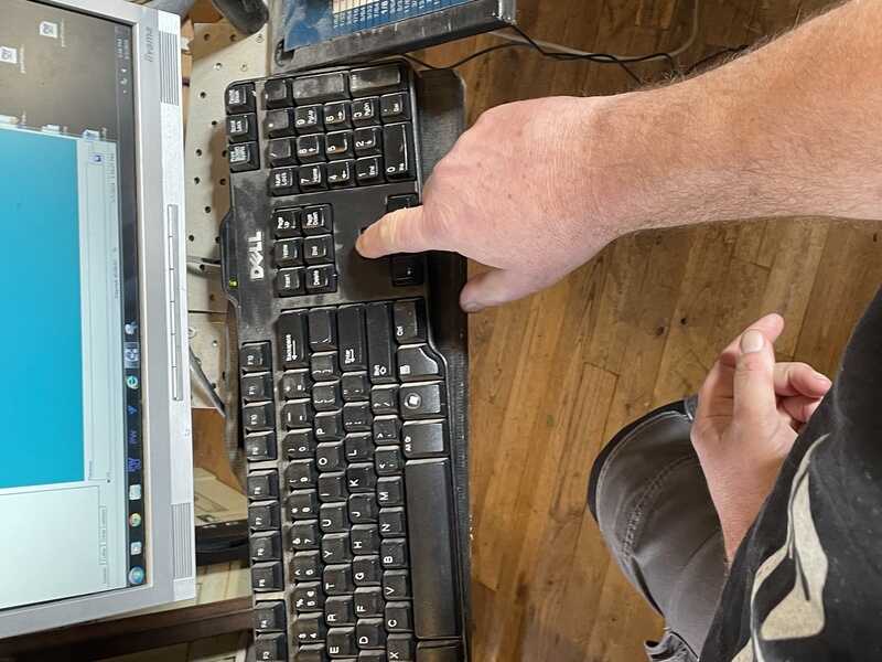
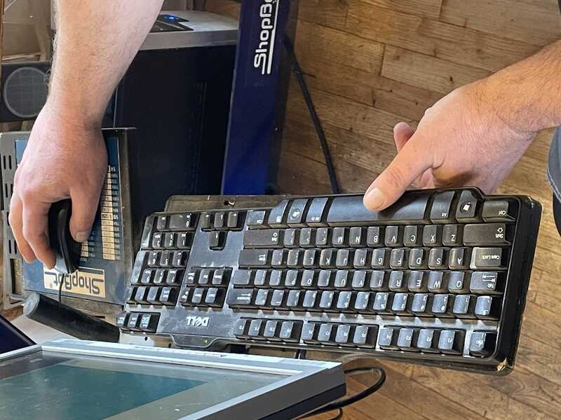
hit K for keypad control
Make sure you work alone, in the sense that nobody is near the machine (or leaning against the machine) when operating the keypad and moving the gantry. Especially motion in Y-direction is dangerous regarding objects and people surrounding the machine.
jogging menu in shopbot controller:
homing (go to limit switches in bottom-right corner)
testing the zero tool before use
Test the zero tool (electric touch plate) before homing. if the plate is not working (for instance because the cable has a defect or whatever) your machine will home in the bed. And ruin the mill, plate, bed, or something else.
let the z-axis drop on the switchplate

home z-axis (automatic... wow..)
Now the Z-axis is homed on the bed (which means in V-carve this also has been set as zero offset).
Before the material can be fixed on the sacrificial layer the bed has to be cleaned, dusted and even sanded first.
cleaning the sacrificial layer
sanding away unevennesses..
The first pass of the machine is usually a drill file with small hole inserts (2 mm, one pass) where screws might fix the material on the sacrificial layer. It is really important to have this job as a separate job. AFTER you have mounted the material using screws you definitely DONT want the mill to drill the holes again.
Now the material can be fixed using the pre-drilled holes:
Keep pressure when fixing material. Not like this...

but like this
When the material is in place, you can set the origin from where you will start milling (typically the bottom-right corner of the bed). It is important to register the coordinates of your new origin (starting position) before you ‘zero’ the machine. When eventually a reset is necessary, you can always move back to this position, relative to the machine home position (with limit switches)
before you hit the set-origin function

make sure to record the starting coordinates (difference between origin and machine zero)
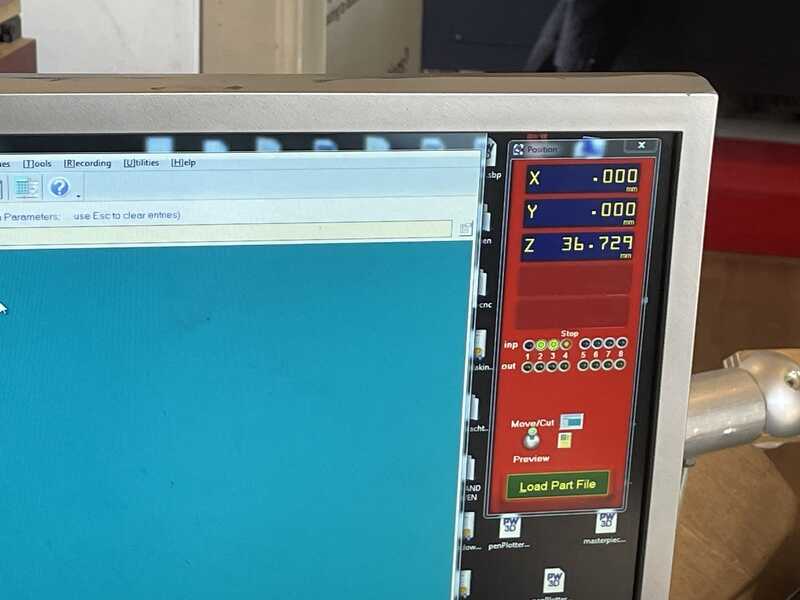
Check whether your zero is your desired origin
Then all the noisy machines can be turned on. Starting with the dust collector in the cabinet behind the shopbot - and finally the spindle motor.
spindle switch key linked to chuck keys

spindle speed is set independently from anything else
Now it is time to start the milling job once more. Carefully listening, watching, smelling. Keep a hand on the spacebar to stop when unexpected movement (or sound or smell or smoke is observed)

now it is time to turn on the air extractor and start milling
keep your hand on the spacebar

First test, apparently with a blunt mill

a VERY blunt mill
The following workflow can be summarised from the notes above:
- measure material, prepare drawing, prepare V-carve (material settings, paths, tabs, g-code)
- clean and inspect bed, insert material (leave room for bed zero Z or use material as Z-origin)
- insert tool in chuck (spindle key is out with chuck keys). machine can be on for movement (jogging)
- start up machine, start up software. zero on machine. check z-height before moving (!),
- zero z-axis on bed using contact plate (test plate contact first with chuck and input-warning)
- set material zero (register coordinates / difference with machine zero)
- load file
- start
- keep finger near spacebar and pray (and look, smell, listen)
group assignment measurements
While Leo and Vera were preparing the group assignment test file in V-carve, I was preparing my design (in the hope that I could do most of the milling that very afternoon). After I was done working in V-carve they completed their design too, so we could do the setting up and running together.
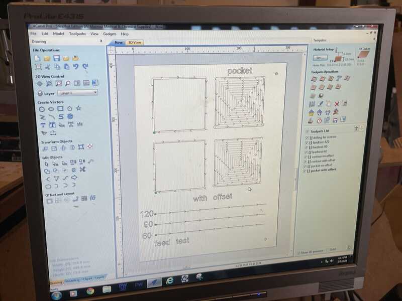
Drawing by Leo and Vera in V-carve, using an offset of 0.2mm

Resulting file (with sharper milling bit than previously used)
In conclusion:
- A runout of 0.1 mm is good for a press fit (given this material and milling speed and milling bit quality). An 0.2 mm runout is probably better for a loose, well fitting fit. see the pictures in leo’s portfolio too.
- Feedrates of 60-80-120 give similar (optically) results.
- spindle speed of 18000 gives smoother (less noisy, vibrating) behaviour than 12000.
individual assignment
inspiration
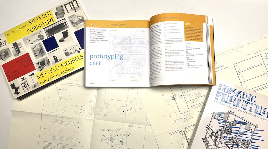
In order to get inspiration and stay away from all those pinterest boards I dived in my bookcase and found the following interesting takes. Rietveld furniture translated to CNC, the great designs by Papenek and Hennessy (nomadic furniture) and another favourite: the Stanford D-School book ‘Make Space’.
ideas
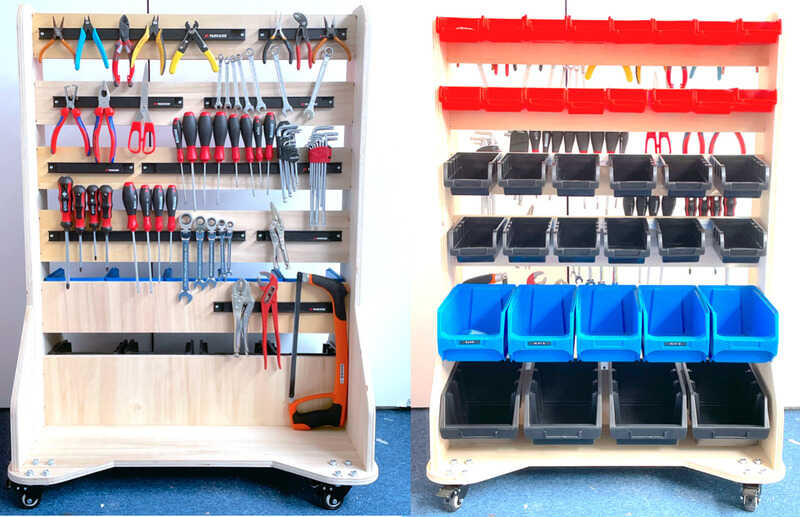
A design from the Make Space book which I like for FabLab Oldenzaal is the prototyping cart. Also in my Unversities’ DesignLab they are widely used and very convenient for kickstarting projects. I am thinking to use one side for hanging bins and the other side I mI for magnetic tool rails.
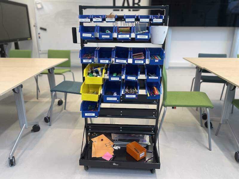
prototying cart in DesignLab Utwente
toolcart design
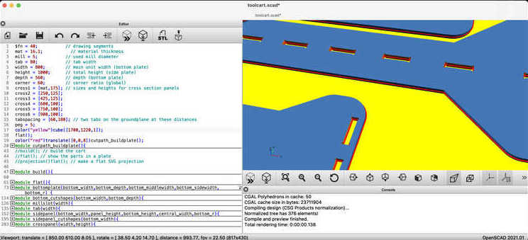
I made my design in OpenSCAD. Using the hull() parameter it is convenient to draw rectangular shapes with curved corners (since OpenSCAD has no chamfering functiions). For the tabs and the slots a T-bone shape is designed and put in already in the design.
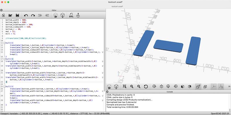
first steps of the bottom plate
Eventually the whole design is made, TODO: better txt) - mill slot, tab, side pannels (all parametric :)
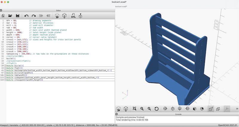
Design of set
the following script is used: toolcart.scad.
In advance I got notified that a sheet of plywood would be available sized 1700 x 1220, 16mm. I tried three options to lay out the parts on the sheet. Deepnest, Inkscape and eventually also OpenSCAD.

Nesting in Deepnest

Nesting manually in Inkscape
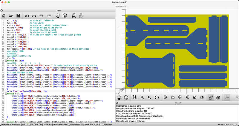
Nesting in OpenSCAD

Final export file in OpenSCAD
- openscad final design - nesting from deepnest and inkscape have been used for inspiration
The advantage of doing your CAM work on the big screen in the lab is that everybody chips in (or wants to show off) their knowledge and experience. (Since this resulted in a very speedy < 2hour milling session I had to buy everyone beers afterwards. Small price to pay… ) . The most helpful tips were:
-
make sure there is at least 20mm between parts as the milling bit will eat away 5 mm. 10 mm will stay in place
-
place tabs opposing each other to keep structural strenght between parts
-
keep enough clearance around the mounting screws (and use them wisely)
-
don’t place tabs in (inside) corners!
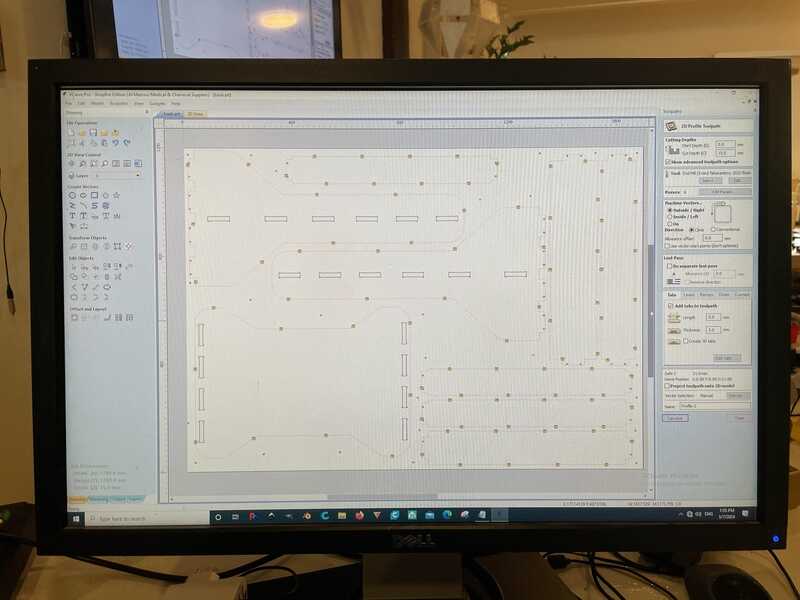
placing tabs in V-carve
Furthermore, based on popular vote and experience we set the following paramaters for pass depth (cutting depth per pass), spindle (router) speed and feedrate:
- z top at the bottom of the material
- take into acount a runout offset of 0.2 mm for toolpaths.
- use climb milling with a negative offset of 0.2 mm
- use a pass depth of 2.5 mm (so 0.5 * mill width)
- set the routing speed a bit conservative (40 mm/s: Henk. Very conservative, 120 mm/s: Saco. based on formulae). In the meantime the results from the group test came in: no visible difference between 40 and 120 mm/s. Henk: go with 40. Resulting milling time estimate: 1:53 hr. (Note that during the milling, after the slots were milled, we increased the speed to 80 mm/s without any noticable differences in finishing)
- the spindle speed was set to 18000. Relatively low in vibration and noise.
Simulation of the work in V-Carve
toolcart milling
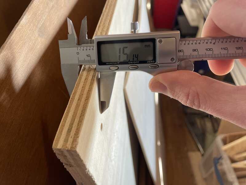
Ai.. 15 mm instead of the promised 16. Long Live Parametric Drawings...

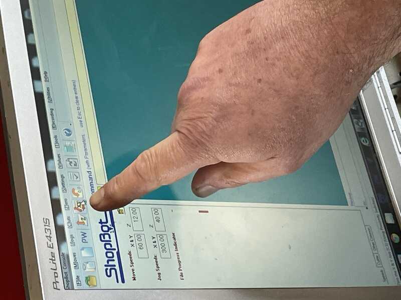
starting the job in Shopbot Control
drilling the mounting holes

fixing the material on the buildplate
drilling the holes
G-code (dialect) being sent.. bits into atoms.. sort of..
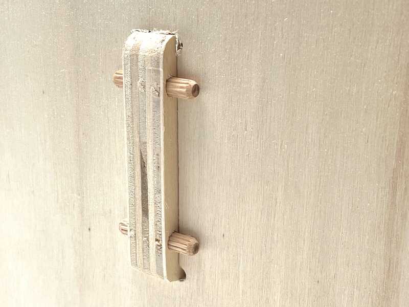
I designed a quick testpiece: one of the tabs and one of the holes to test whether the 0.2 mm runout compensation would offer a good fit:

first testpiece with 0.2 mm runout settings

fitting the testpiece
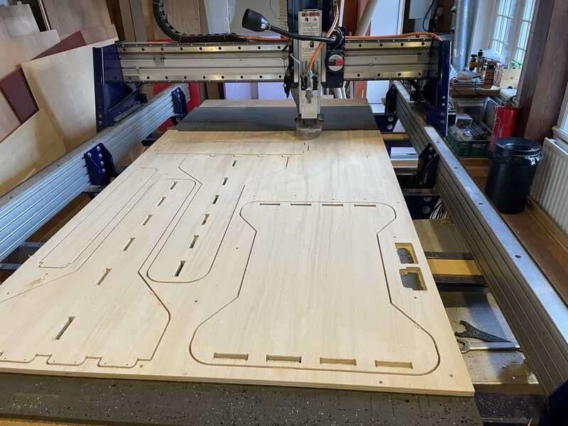
Milling halfway

the total progress picture of shopbot control
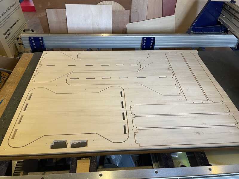
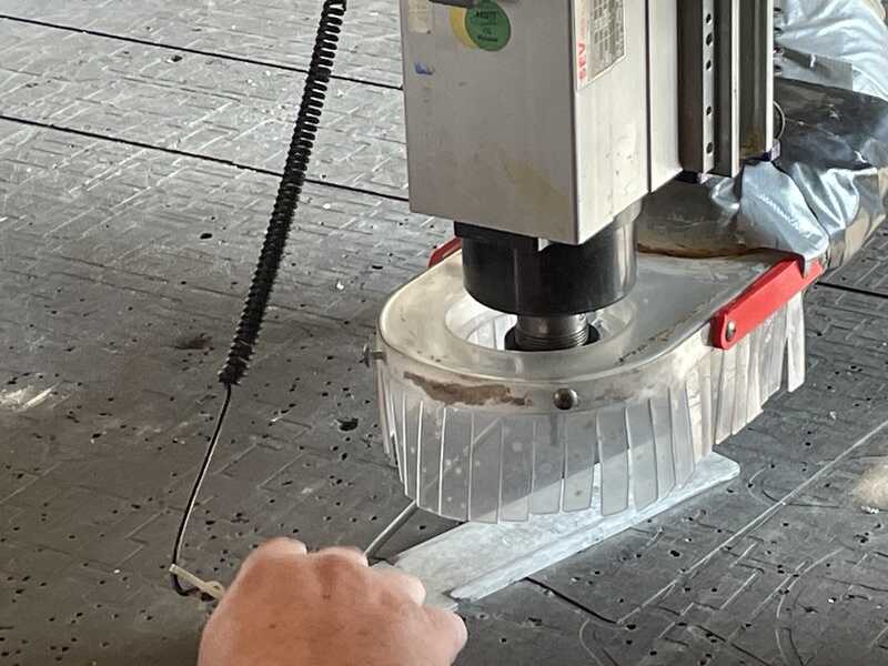
cutting done
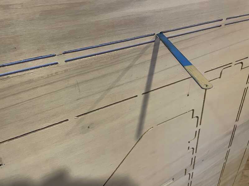
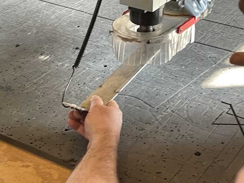
cutting the tabs with a hand saw blade
toolcart assembly
I took the following steps:
- using the band saw to remove the tabs (now I realy appreciated the advise to not put them in corners)
- using sandpaper (80 grain, 150 grain) to sand down the edges (30 min of work)
- use a standard 6mm drill to enlarge the dowel holes. Sadly I was not able to find a source of 5mm dowels at short notice
- sand down the tabs of the two side panels a bit further in order to enable a secure (not-too-violent) fit
- cut aluminum z-profile to length and drill mounting holes (4mm, center, left, right)
- mount the castors on the base plate. Originally I intended to use the 16mm wood screws that were supplied, but I had to adjust the whole design to 15mm. Instead I used M8 x 20mm bolts with washers and locking nuts.
- mount one of the side panels in the base plate
- place the bottom cross panel, hold the other side panel in place
- place all other cross panels and press both side panels together for everything to fit. This worked surprisingly smooth.
- fix the (still loose) side panel in the bottom plate. This needed a bit of work with a rubber hammer
- slot all dowels in place using a small bit of wood and acrylic hammer.
- hang boxes, mount magnetic tool rails

all aditional parts

try one: castors with screws

bolting the castors
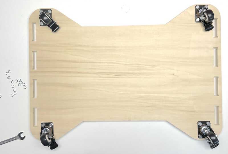
all four wheels in place

z-profiles mounted on cross section plates
connecting tabs with 6mm dowels
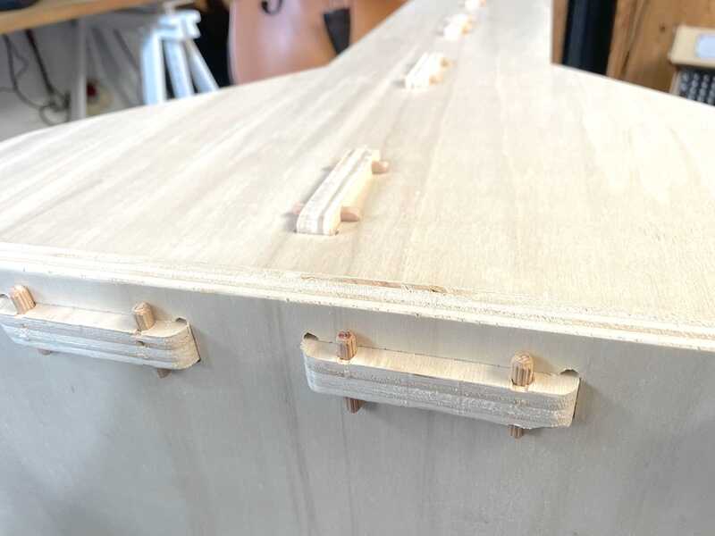
all joints fixed in place
more CAM
after a succesful build using a design in OpenSCAD with V-Carve doing the heavy lifting CAM wise, I thought it might be good to explore other processes for CAM as well (as we don’t have a shopbot, so we’ll have to find an alternative for V-Carve - and preferably also stay away a bit from big heavy resource hungry and (eventually) expensive packages like Fusion360)
openscad + inkscape + UGS
trying to use inkscape to do cam. First using dynamic offset to generate the paths, then use gcodetools to convert them to G-code and use UGS to check how they work out size- and path wise..
another option is in OpenSCAD: offsetting can be done using minkowski and using the 2D offset function
In the following file two methods are tested: toolpath-offset.scad
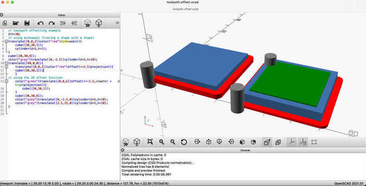
Creating an inside ant outside path offset in OpenSCAD
I tried using the same approach for the full drawing - the ‘offset’ function works faster than minkowski:

outer contour with offset

different drawing for an inside shape
path-offset in openscad

complete drawing with path-offset, inner and outer shapes in OpenSCAD
Next up I used the G-code tools plugin for inkscape to convert the path to Gcode and use UGS to do a basic check:
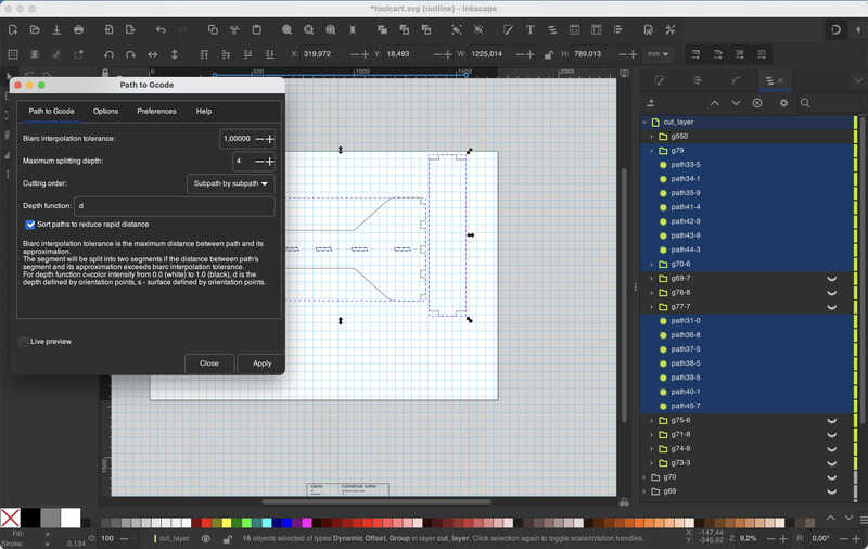
generating g-code with inkscape

checking inkscape's g-code with UGS
Easel
Easel is a very user friendly web-based CAM tool, supporting many different milling machines. It can do basic operations (pocket milling, contour milling, tabs, conventional / climb) but does not offer the same flexibilty or precision V-carve offers. The price-tag (montly subscription) is also non-trivial.
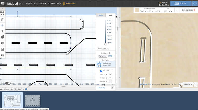
Job selection per object in easel

using easel to process the
Makerhub and MakerMade Maslow M2
Appears to be just a G-code sender for Maslow / MakerMade based machines. It speaks the Maslow dialect at 38400 bd.
I tried using the MakerMade M2 mill we set up at Fablab Oldenzaal but sadly we experienced some weird software problems. After spending some hours with the kind guys at their helpdesk in Plano, Texas - we still didn’t manage to narrow down the source of the problems..
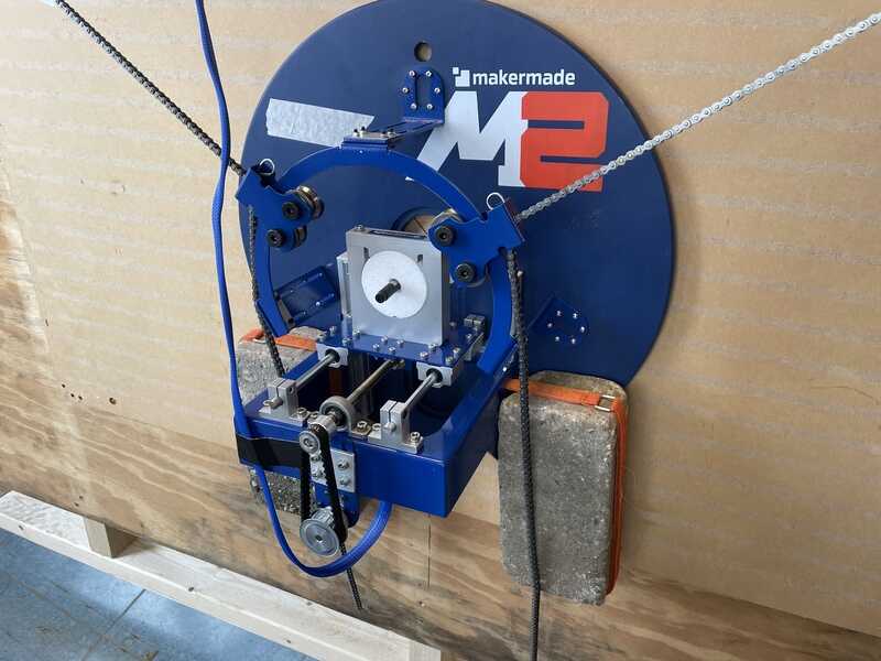
MakerMade M2 being configurated
KiriMoto
Another web-based CAM tool to check. Sadly I did not had as much time as I had for Easel and others. It seems to be quite powerful at first sight. Have to go and use it further for a better verdict.
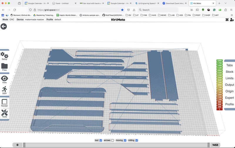
first import in KiriMoto
learning outcomes
Learning outcomes of this week are:
- Demonstrate 2D design development for CNC milling production
- Describe workflows for CNC milling production
evaluation checklist
The task list for this first week (for personal reference)
- Linked to the group assignment page (linked in this page)
- Documented how you designed your object (something big)
- Documented how you made your CAM-toolpath
- Documented how you made something BIG (setting up the machine, using fixings, testing joints, adjusting feeds and speeds, depth of cut etc.)
- Described problems and how you fixed them
- Included your design files and ‘hero shot’ of your final product
lessons learned, tips and tricks
(or, the most insightful mistakes I made)
- We couldn’t get the Maslow / MakerMade M2 up and running, even after spending some hours on Zoom with their kind helpdesk - support. This is definitely on the list for the lab.
- Eventually it would have been better if I would have tested the complete joint (including dowels) before milling, now the fixing is a bit critical. No dowels have broken out (yet) but the risk is definitely there.
- It was interesting to realise how much the direct physicalities of the process play a role in how you prepare your digital design (and files). There is much more insight and steps involved (and much higher risks of ruining something) compared with lasercutting of 3D printing.
left for todo
- Look into other CAM tools. Perhaps don’t be squeemish, get it over with, and try Fusion360 too.
- get our MakerMade hanging CNC Maslow machine working. We tried to get it up and running for this week, but the control hardware is giving unpredictable ’episodes’ or ‘absenses’ which will screw up a milling operation.
- make serious work on the dust-extraction for the Maslow machine. Find a good spot, have a separate chamber for the dust collector, a good flexible lightweight hose, etc.
- find another tool (or program our own) to convert the OpenSCAD files into G-code. Similar to the direct-G-Code control of 3D printers, the heavy lifting (generating a nice offset path for the router) has been achieved.
reflection
It was nice that the milling was a relatively smooth ride - probably thanks to pooling the wisdom of the present crowd - and also a well prepared parametric drawing. I needed to adjust everything for a different material thickness on the fly, the OpenSCAD design behaved very well in that respect.
Perhaps the drawing and design were not the most complicated or aesthetically pleasing, but I set to make something I really needed to use (in the shop), maximising material use, without fastners. (I used wooden dowels. guess they don’t count as screws or glue, but might be considered fasteners all the same. Oh, well…)
It would have been even smoother if I would have had checked the availability of 5mm dowels before setteling on the drawing like this. If I had known that I would have had to use 6mm dowels, I would have extended the tabs 2 mm and used the mill to do a 6mm pocket clearance instead. Now I needed to do manual drawing, the top-layer of the wood around the edges has come of for a few mm at some of the holes, and the ‘flesh’ above the dowel holes is a bit thin. Anyway, the design seems to be holding out fine for now.