computer-controlled machining
Topic(s) of this week
- computer-controlled machining (video, review)
- Demonstrate 2D design development for CNC milling production
- Describe workflows for CNC milling production
Hero shots
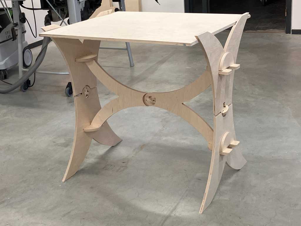
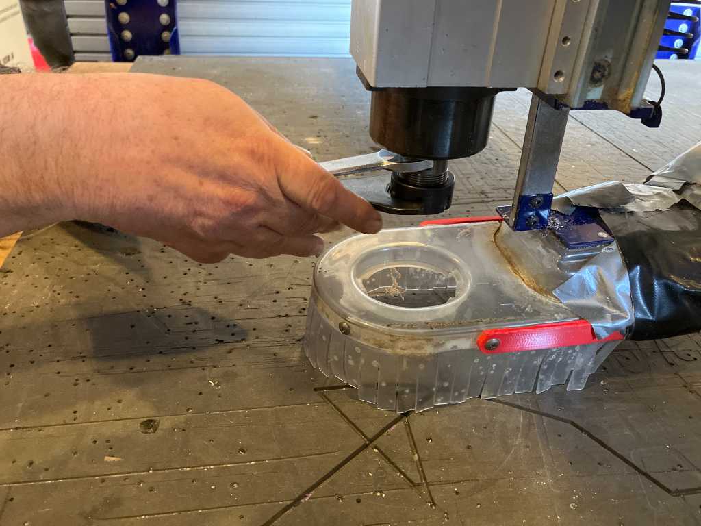
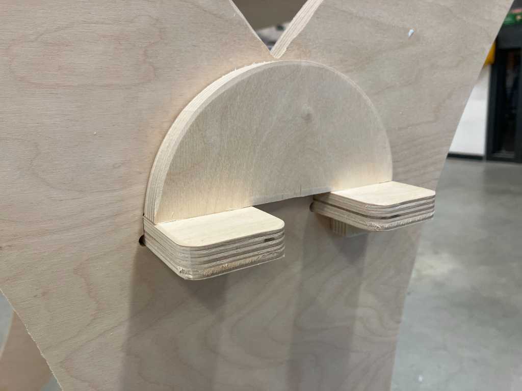
Here’s something BIG and something small. My (uns)table and a test for my final project.
Assignments
Group assignment
- Complete your lab’s safety training
- Test runout, alignment, fixturing, speeds, feeds, materials and toolpaths for your machine
- Document your work to the group work page and reflect on your individual page what you learned
Individual assignment
- Make (design+mill+assemble) something big
What I think I already know
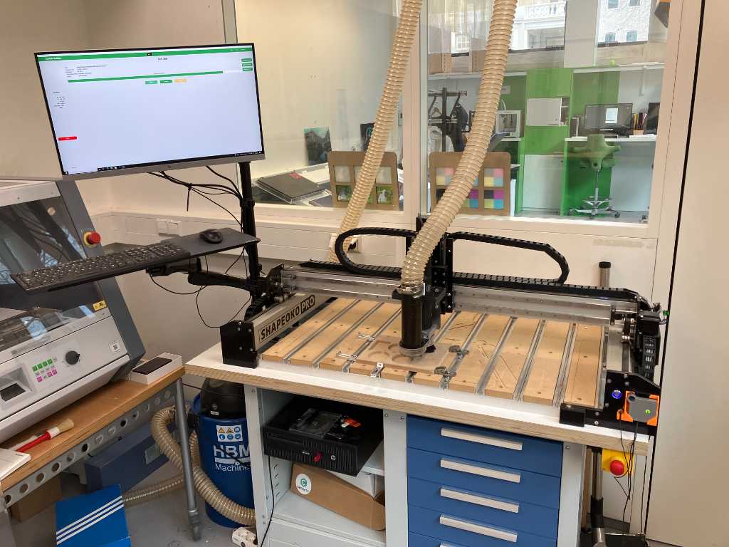
We have a Shapeoko Pro XL in our fablab. I’ve used it a few times now. I also did some preliminary tutorials to get more acquainted to the specific terms of CNC milling.
What I want to learn
CNC milling (and molding & casting) is most probably the week that I look forward to the most of all fabacademy. I basically want to learn it all :-)
SSTM planning
Supply
| Day | Supply | Tasks |
|---|---|---|
| Thursday | 08:00-09:30 (train) | - |
| 10:00-18:00 | WAAG | |
| 211:30-23:30- | documentation | |
| Friday | 9:00-13:00 (fablab) | Make new FP pressure sensor |
| Weed sensor | ||
| Saturday | design stand | |
| Sunday | design stand | |
| Monday | 9:00-17:30 (fablab) | CNC milling |
| FP mechanical design | ||
| 20:00-23:00 | design stand | |
| Tuesday | 9:00-17:30 (fablab) | more CNC milling |
| 20:00-22:00 | Documentation | |
| Wednesday | 9:00-11:00 (fablab) | Documentation |
| 11:00-12:00 | Local review | |
| 12:00-13:00 | Regional review | |
| 14:00-17:00 | Neil time |
Tasks
Have you answered these questions?
- Documented how you designed your object (something big)
- Documented how you made your CAM-toolpath
- Documented how you made something BIG (setting up the machine, using fixings, testing joints, adjusting feeds and speeds, depth of cut etc.)
- Described problems and how you fixed them
- Included your design files and ‘hero shot’ of your final product
- Leave feedback in Nueval that this weekly is ready for evaluation.
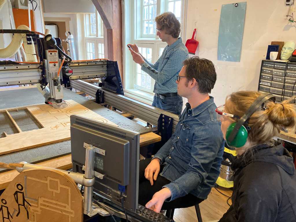
WAAG session and group assignment
Saco gave us a workshop on CNC machining principles.
We’re going to do 2.5D. That means in Z direction you can only go up&down. For official 3D would be when you’d have an extra axis.
climb (NL: meeloopfrezen), conventional (NL: tegenloopfrezen). We’re going to use climb mainly. Reason is that when the tool gets to the material, it immediately bites into the material. The finish is smoother. Forces are varying so that could lead to more inaccuracy. But that’s not really important in the things we do.
Step over: percentage of the milling bit that interacts with the material. Usually around 50%. For wood can even be bigger. Lower percentage reduces the chip load.
Cutting speed is related to diameter of the mill (RPM x D x Pi/60).
Cutting speed to high: burning wood.
cutting speed to low: splinters.
Cutting speed is related to spindle speed and feed rate. So the speed of one flute cutting in the material. Cutting speed: speed of the tool relative to the material. For ordinary tools with wood it’s usually 20 ~ 60 mm/s.
Spindle speed: recommended RPM for 6mm end mill: 9000 RPM.
Feed rate: Speed of movement. not related to diameter of the mill. But related to number o flutes.
Recommended feed rate shopbot: 20~120 mm/s.
Feed rate too high: high forces on the machine
feed rate too low: bad cutting and risk of burning wood.
Chip load is the thickness of the chip. So amount of material removed per cut.
chip load: usually 0.1 ~ 0.5mm thick and 1 ~ 5 mm wide.
Toolpath generation can be done using several programs:
- V-Carve. Has a t-bone “generator”
- Fusion 360. t-bones have to be designed
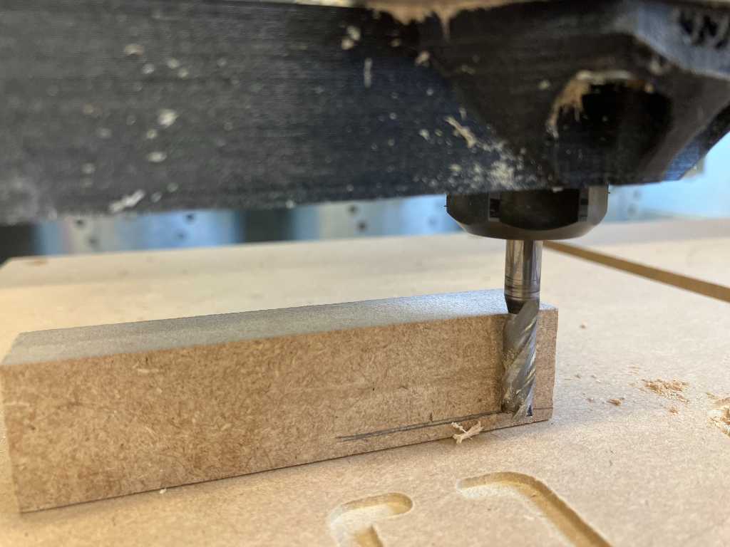
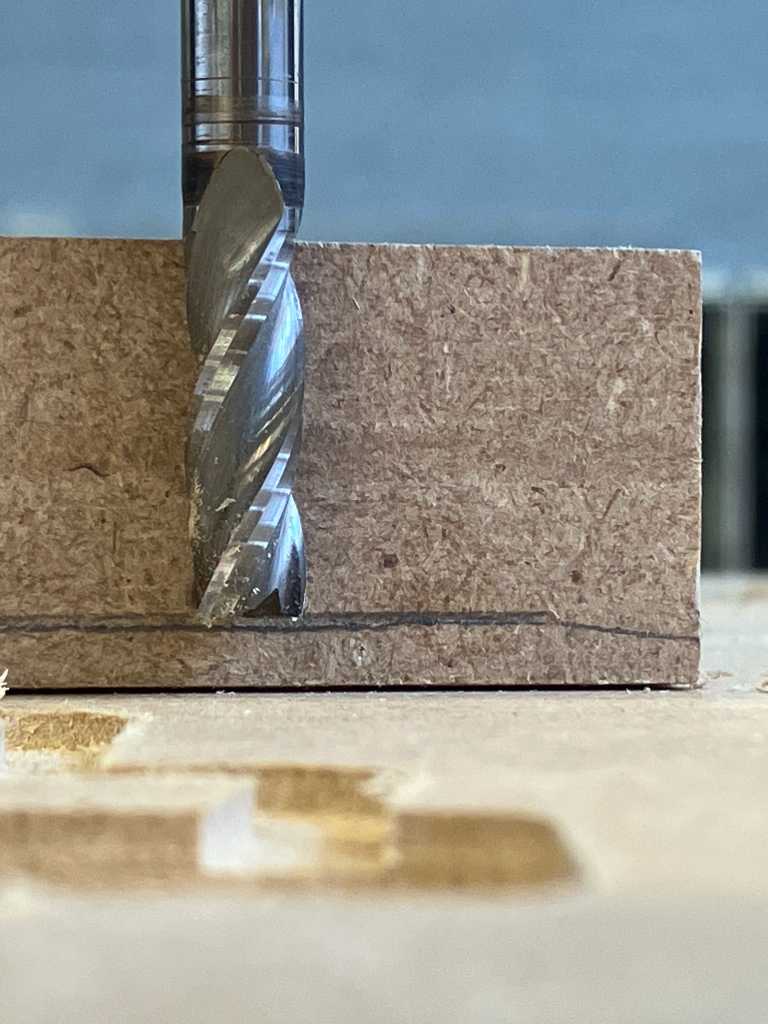
T-bone and dogbones are different things.
Due to machine variations there’s always some room for error. If you mill a square and do climb milling, the bit bites into the material and the bit is forced into the material. If you do conventional milling, the bit is forces away from the material. So it doesn’t really exactly match the designed toolpath.
If you want to bend wood, mill deep enough. You should leave around 3mm. Otherwise it’ll snap.
To do joinery, check https://www.fablabifurniture.org/50-digital-joints.
V-Carve
WAAG uses Vectric V-Carve to do toolpath generation. The way to use it:
- Create new file
- In job setup
- Job size = stock size
- Material (Z) = set up thickness of stock and Z0 position
- No XY offset
- Units = metric
- Create a design
- Model - Import component (DXF, SVG, etc, so vectors)
- Or draw using the drawing tools
- draw circles where you want to screw the stock to the workbed. Use diameter of the drill you’re going to use. E.g. 5mm
- Check if the vectors are fully closed (especially if you import).
- Edit - select all open vectors
- Use Join open Vectors tool
- For inner corners create fillets - at least the size of the diameter of the tool
- Set tool radius
- select fillet type (normal, dog-bone, t-bone, Plasma)
Example: dog bone on lower side, t-bone on top side.
- Create toolpaths in toolpath section on the right hand side
- Drilling toolpath (always start with this-> required to fix the stock to the table using screws)
- start depth: 0 mm (see drawing next to it)
- Cut depth: 2 mm (see drawing next to it)
- check show advanced toolpaths
- machine vectors now shows Allowance offset
- tabs now shows option to create 3D tabs -> more fluid movement tabs
- Select tool e.g. 5 mm end mill
- Don’t make changes in this window
- instead, select this tool and make changes later on
- otherwise database will be changed
- path depth = distance tool goes up when going to another toolpath (this is distance above stock thickness, so you don’t need to account for stock thickness)
- Use vector selection order (processing order is the order in which you select the paths) -> hold shift to multiple select
- Hit calculate
- Profile toolpath
- start depth: 0 mm (see drawing next to it)
- Cut depth: 2 mm (see drawing next to it)
- Select tool e.g. 5 mm end mill
- pass depth -> diameter of the tool
- spindle speed: saco uses 12000 rpm, waag uses 18000 rpm
- feed rate: 50 mm/s
- plunge rate: 20 mm/s
- Select if the vectors need to be machined outside/right or inside/left (or on vector)
- Select direction (climb or conventional): use climb
- Add tabs
- 5mm x 3mm is standard according to the software
- add them with e.g. 100mm distance (use edit tabs button to add them automatically or manually)
- Pocket toolpath
- now step over setting is important. You can use 50% but better to use 40% or preferably to 60%, because otherwise your milling twice over the same area, which will eventually create visible the milling lines
- Edit passes -> passes are automatically calculated. If you want you can change pass depth of every pass. But this is hardly ever used.
- Clear pocket
- offset -> going from inside to outside
- raster -> creates X line and then up in Y direction and then another X line
- pocket allowance = kerf offset
- if climb is used, the offset created by machining would turn out to be a couple of tenth of mm.
- pocket allowance is single sided so set to 0.1 or 0.2mm
- can go negative as well
- With climb -> use negative values for allowance. because with climb the tool want to go away from the vectorline
- with conventional -> use positive values for allowance
- Drilling toolpath (always start with this-> required to fix the stock to the table using screws)
- before saving toolpath: check which toolpath is selected!
- Better to create separate files for every toolpath. Because that gives better control
We’re going to make this as designed by Saco during the workshop:
shopbot
Henk gave us a workshop on the shopbot. The masters and their machine:
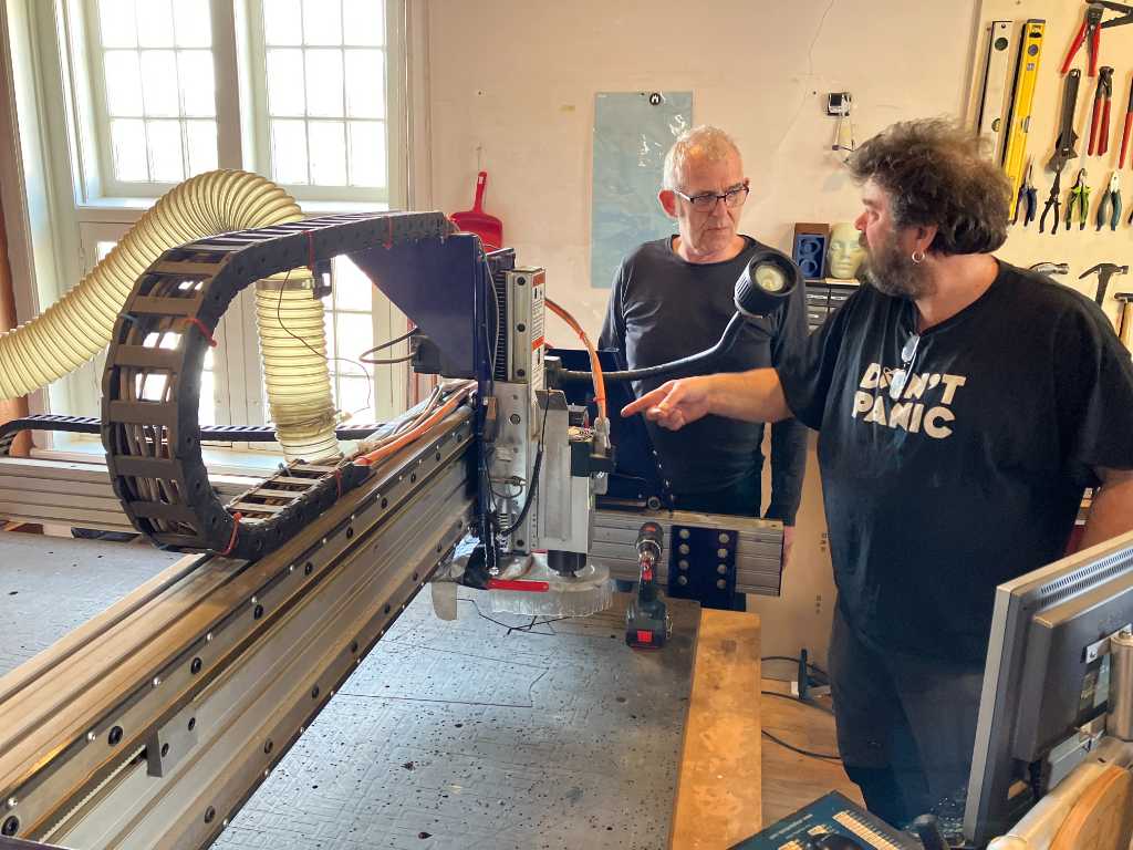
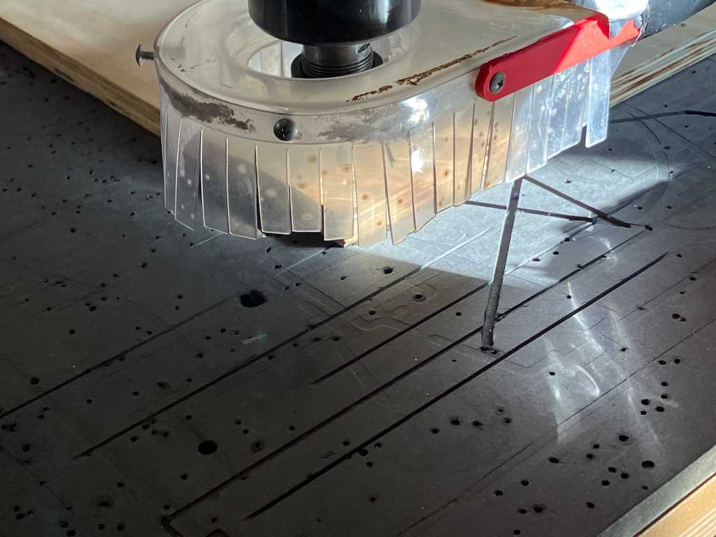
This huge end mill is used to level out the sacrificial layer. The mill is called a surface mill:
Safety first
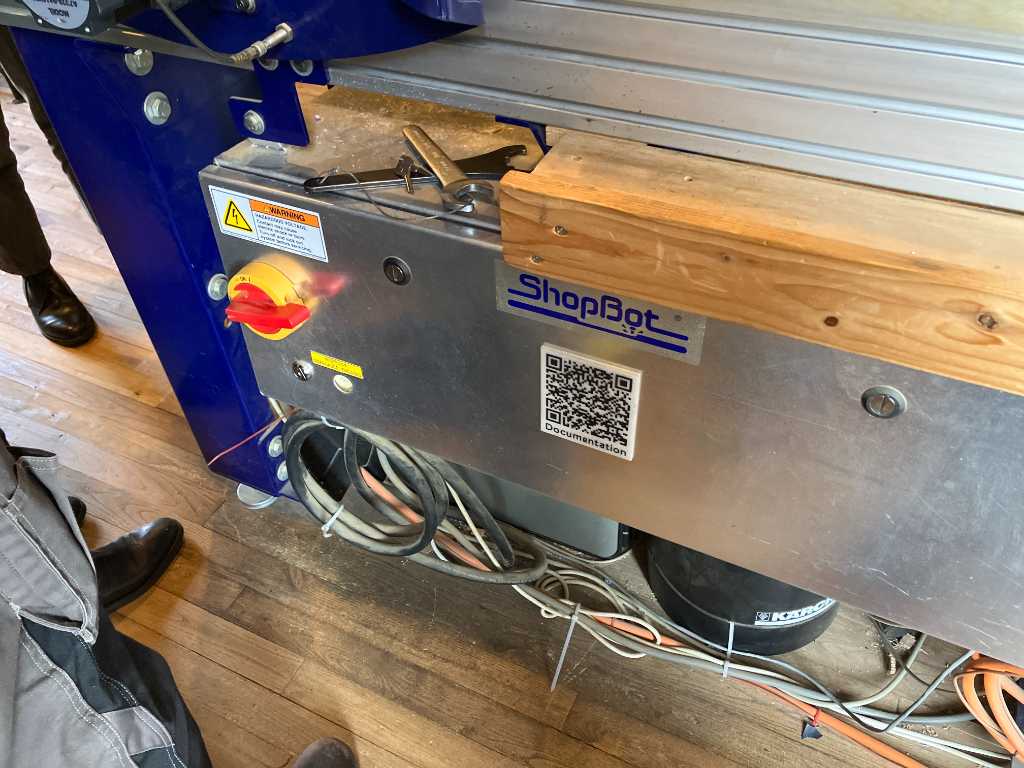
Here’s the big red ON switch:
Make sure there’s room on all sides of the machine. You don’t want the gantry to hit something:
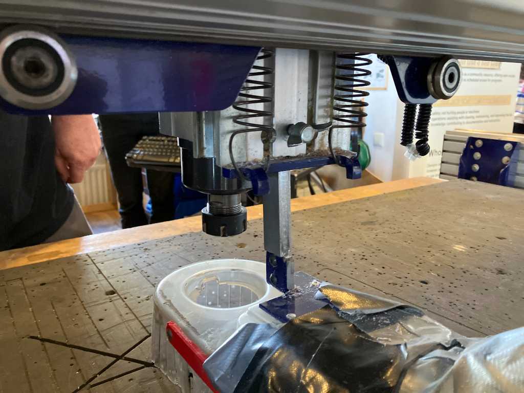
This is the spindle:
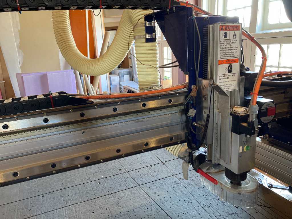
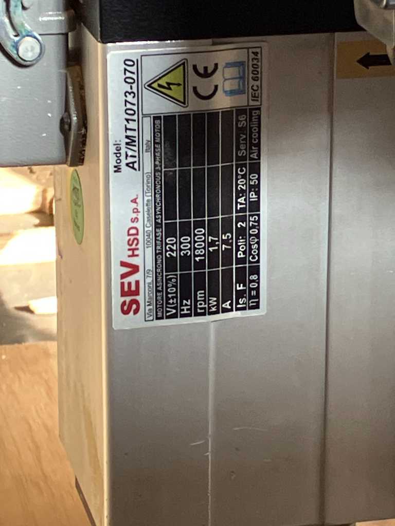
Specs of the spindle:
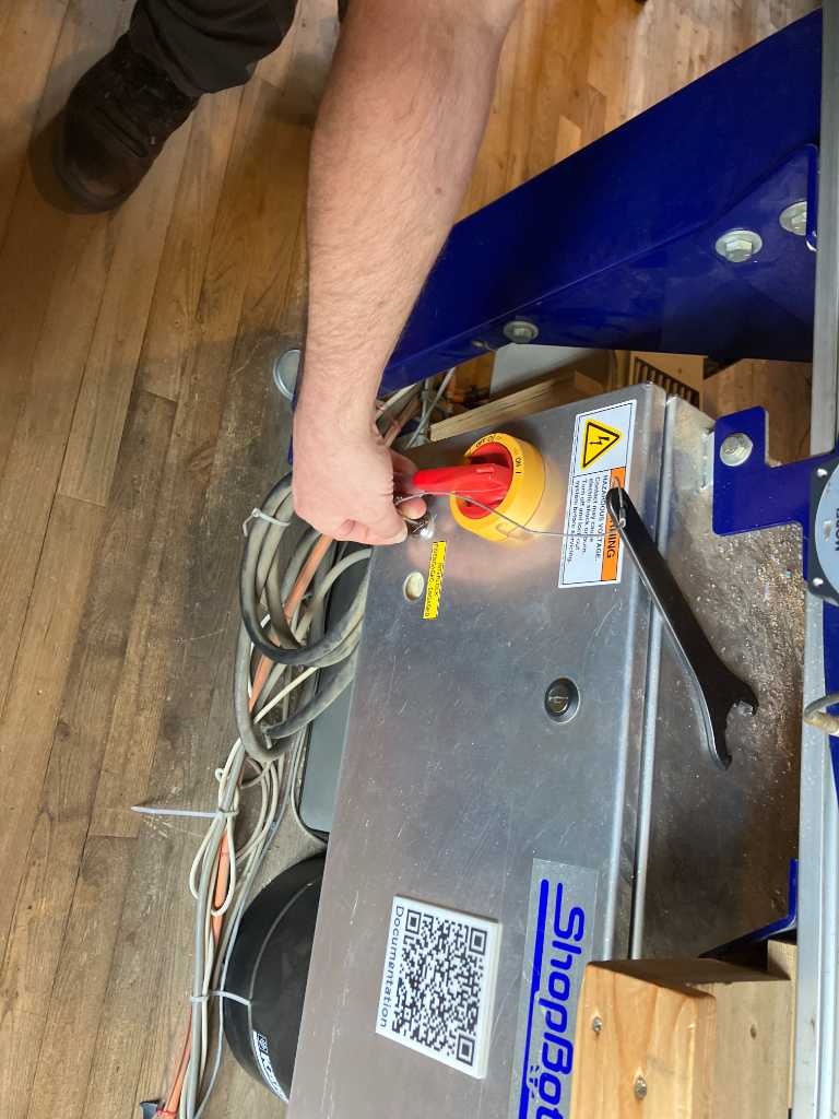
The tools to open the spindle are attached to the key that is used to turn the spindle on. This is a safety measure. Now you can never have a running spindle when you try to change the tool.
Here’s how to turn on the spindle with the key:
Always be cautious of fire. This is the foam fire extinguisher:
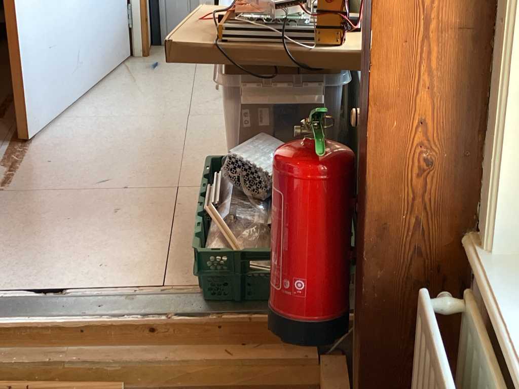
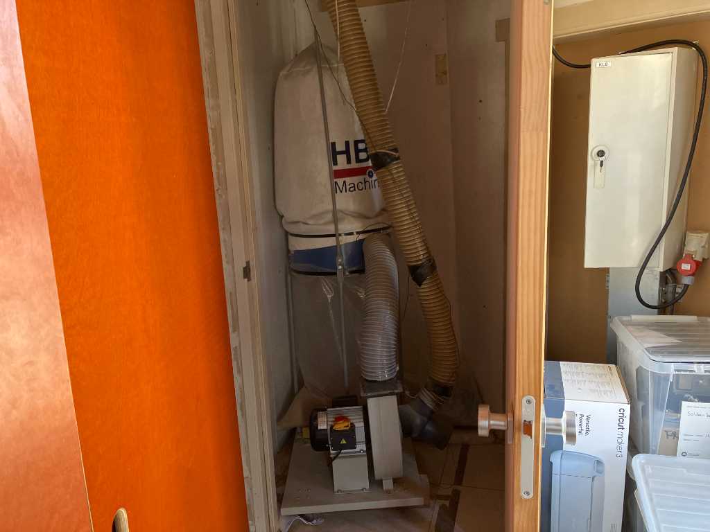
Dust collector is in the closet behind the shopbot. On/off switch for the dust collector is here as well.
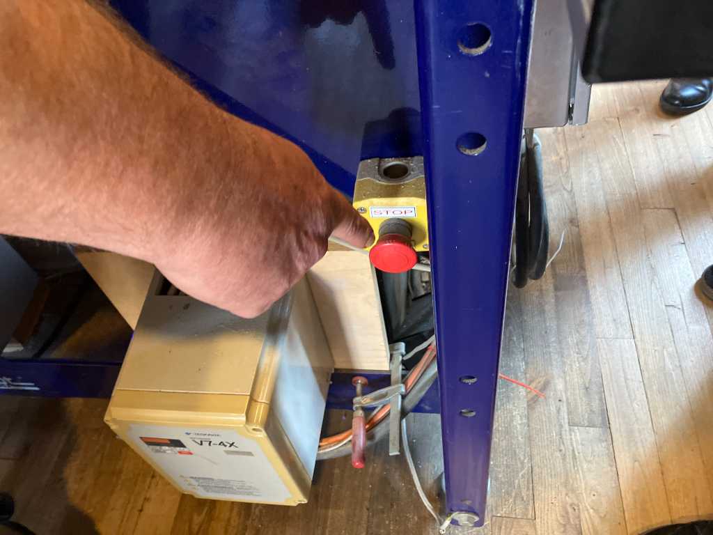
Always stay at the machine while in operation. Here’s the emergency stop button. Be careful, this will only stop the X/Y/Z axis. It will not stop the spindle, you need the key for that!
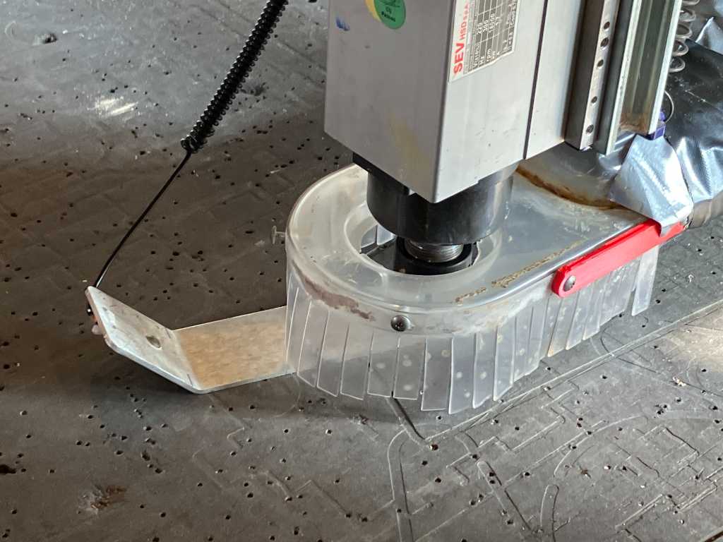
Loading a milling bit
There’s a wingnut on the back of the spindle. Use that to lower the dust extraction cover.
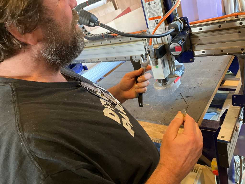
Use the two tools to open the collet nut:
There’s a box full of collets. Mostly never used, because how many sizes do you really need…
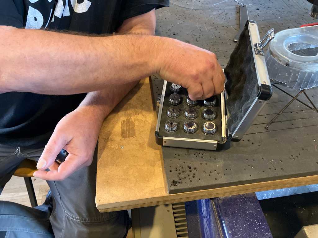
The collets and tools used at WAAG are metric only. Nice!
Here’s a 5 mm 2 flute end mill:
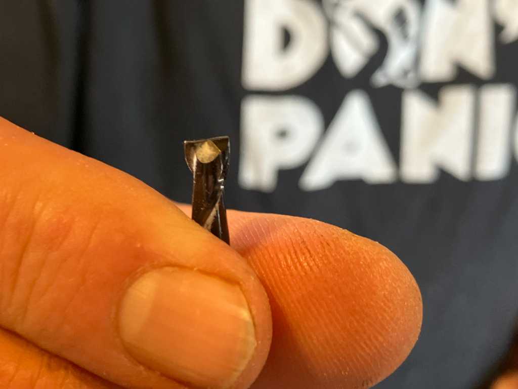
Put it all the way into the collet, but making sure the black part of the bit is not in the collet. Reason is that the black part is hardened steel. The collet doesn’t grip on it as good as unhardened steel.
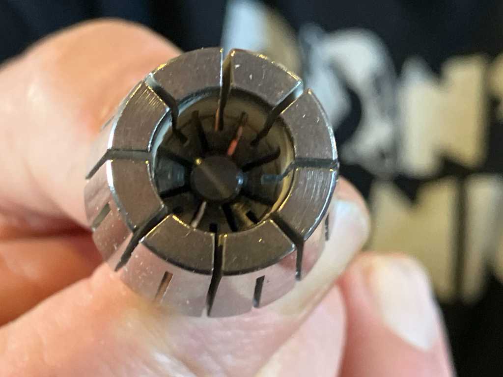
Put the collet into the nut and press firmly. It should click into place. Next put the assembly back into the spindle, tightening the nut. Finally put the dust extraction cover back into place.
operating the Shopbot
Turn shopbot on using the switch on the side.
Start the shopbot software:
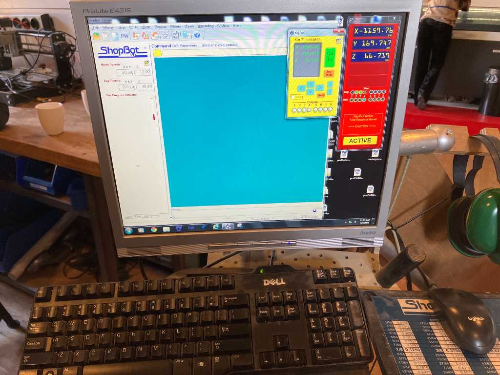
Press K on the keyboard. This opens the keypad with which you can manually control the shopbot axis. Use keyboard arrows to control XY. Page up/down is Z. Note that the long side of the shopbot is X direction. The short side is Y direction.
It’s alive!
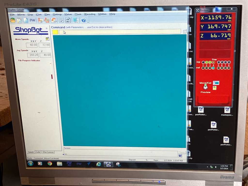
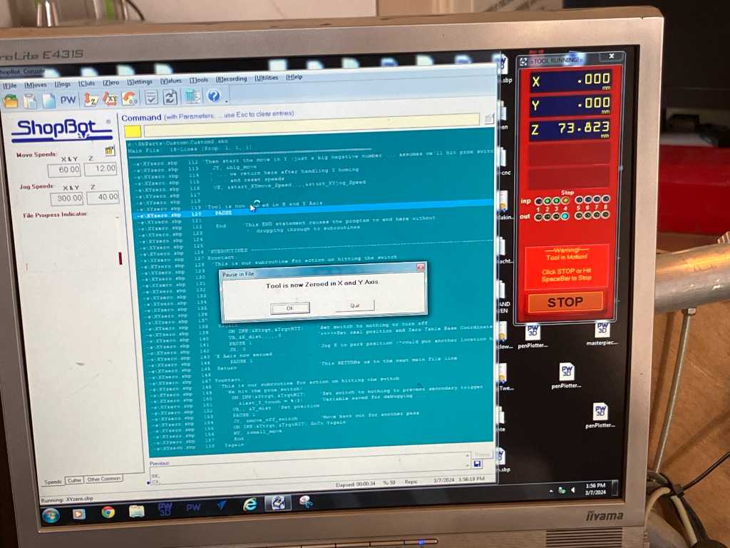
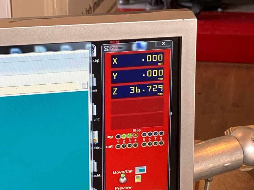
Next is XY homing. Hit the Zero X/Y button. Careful, the machine will move!
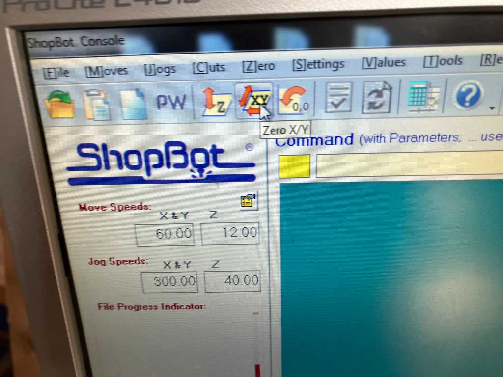
The software will notify you when XY Zeroing is done:
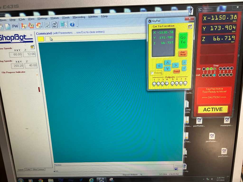
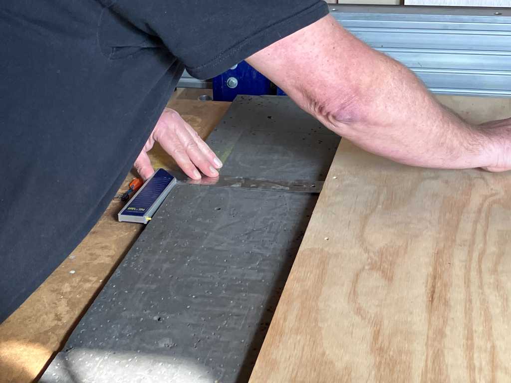
Next on the list is Z zeroing (on the workbed):
Tap the milling bit with the metal plate. Input 1 will turn green when it touches mill:
Put the metal plate right underneath the milling tool:
Click zero Z button:

The spindle moves down until it touches the plate. Z zeroing is done now.
Now remove the plate and move Z further up so you can load the material.
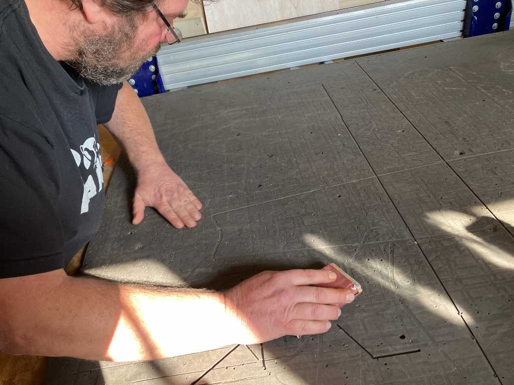
Make sure workbed is completely flat. sand if needed. Especially where screws have been put in:
Place stock material
Do it perpendicular to the workbed
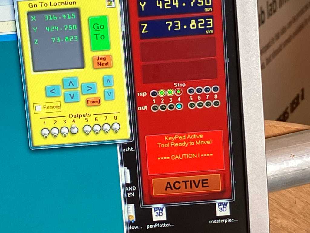
Move the spindle above corner of stock and make a note of this X an Y position
Zero 2 axis (X&Y)
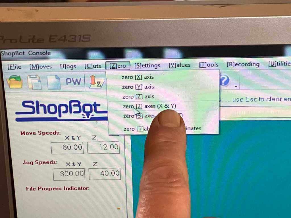
X and Y will become 0 now
Copy tool path file from usb to computer (on the desktop, yay).
Turn dust collector on (in closet in the back)
Turn spindle on with key.
Manually set spindle speed
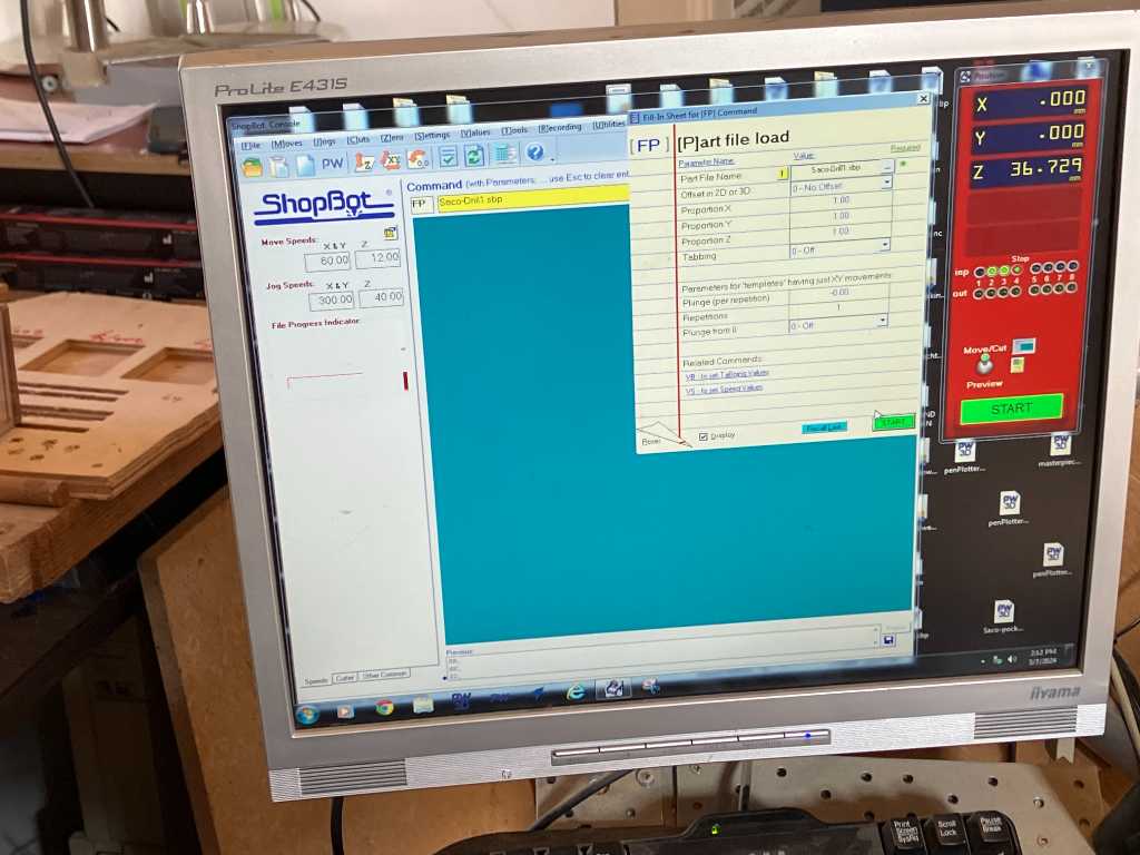
Load path file
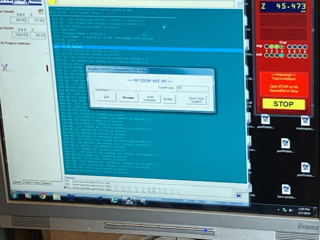
Press start.
Keep your hand at the spacebar to be able to quickly pause!!!
When you hit space to pause you see this:
First drill the holes so we can fix the stock using screws.
Turn off spindle.
Use woodies screws to fix the plate
Press to put weight on the stock!! This is wrong:
This is right:
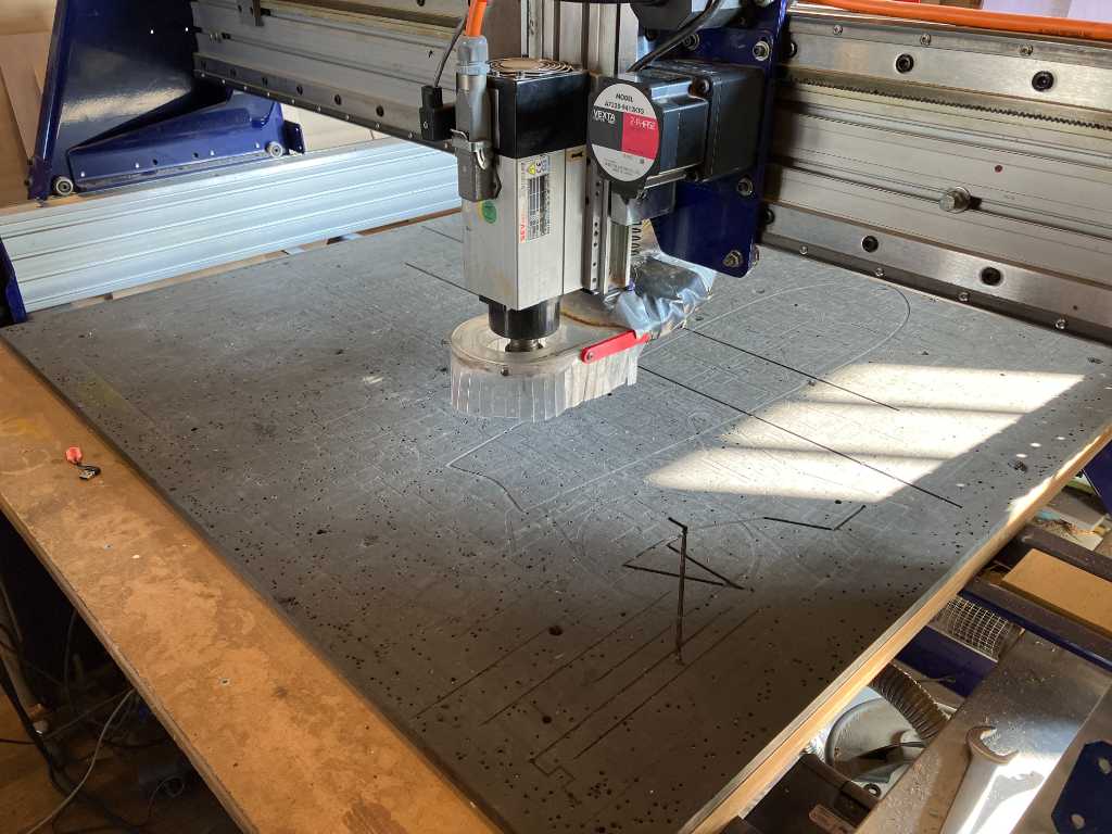
Let’s get milling:
Lots of noise when put on 12k RPM.
When on 18k RPM sound is much better.
Watch closely and stay alert
good chips:
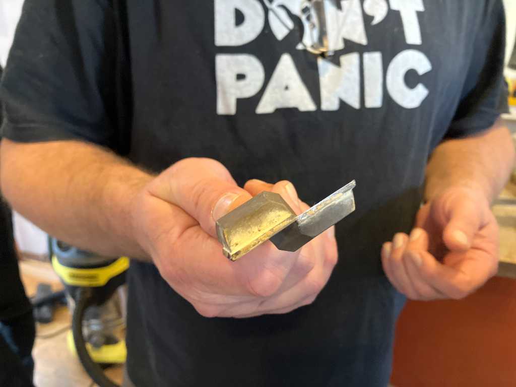
Quite some burrs. Tool is blunt. Also pass depth might be too much. Is currently equal to diameter size of the tool. Henk’s advice is to lower the pass depth to e.g. 1/2 of diameter.
We’re trying it again with a different end mill. To check if its the tool that gives these bad cuts.
And that helped. Right side on the picture is with sharper bit. This is how it supposed to be on this machine with this material. RPM was set to 18K RPM.
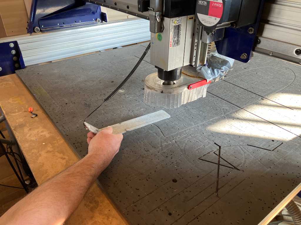
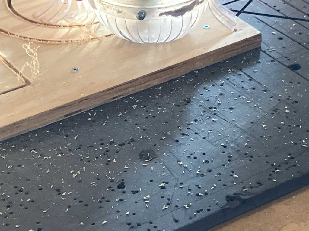
group assignment runout, alignment, feeds
Together with Vera, we created a design that tests runout, alignment and feeds.
The design and setup of the file is documented in the documentation of vera.
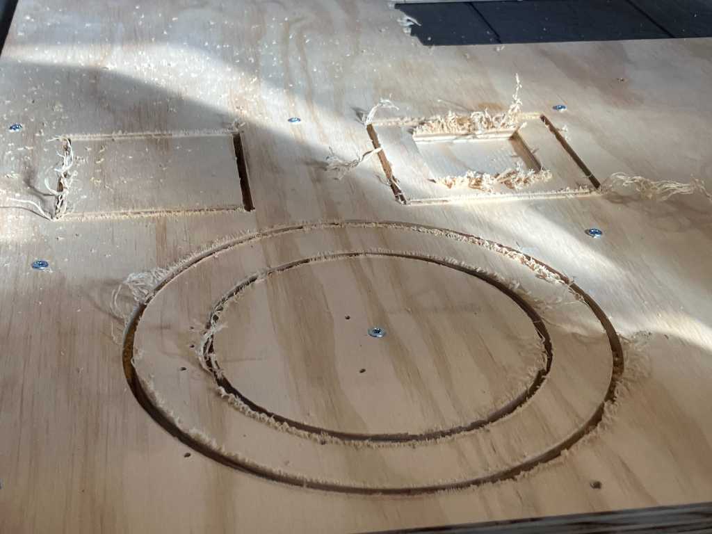
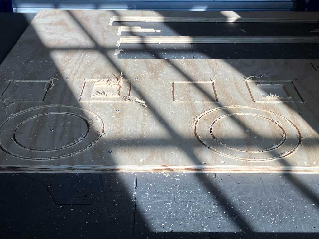
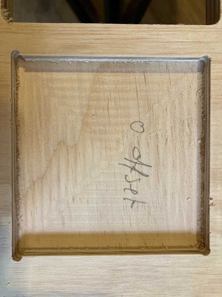
Runout is tested because we made 2 squares of which one will be milled out (contour routed) and the other will be a pocket. The first should fit into the second. We also made a copy of which we used an offset of -0.2 mm to check if the fit would be better.
With the contour router squares, we can also check alignment, because the 2 diagonals of the squares should be equal. If not, the squares would be like a trapezoid, indicating the machine isn’t fully aligned / squared.
Feeds are tested by routing 3 straight lines with different feed speeds: 60, 90 and 120 mm/s. The middle is the WAAG default.
Result:
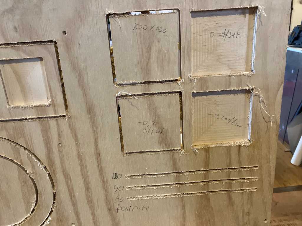
Feedrate test:
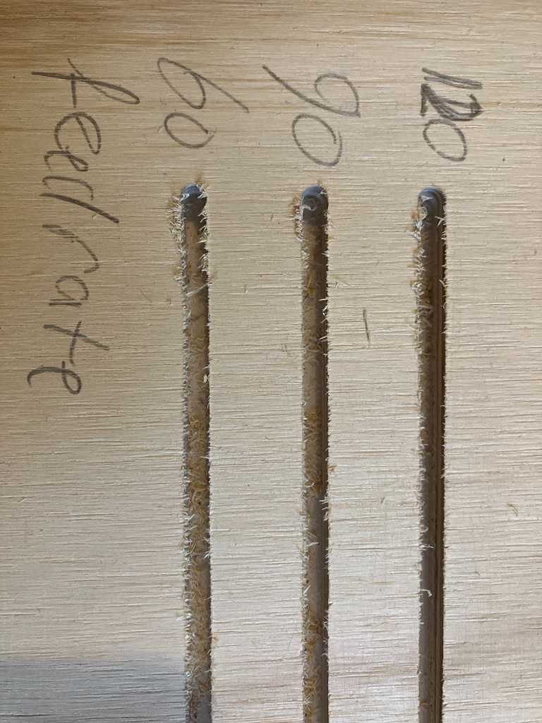
The three straight lines a don’t really differ a lot. Our observation is that the 60mm/s made a bit more noise, indicating that this is too slow. There was really no much change between 90 and 120 mm/s, indicating that the machine (with this specific end mill and piece of wood) can run quite a bit faster than default without doing harm to machine or stock.
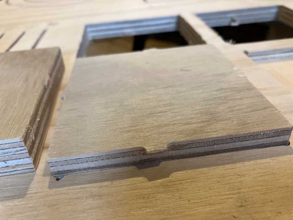
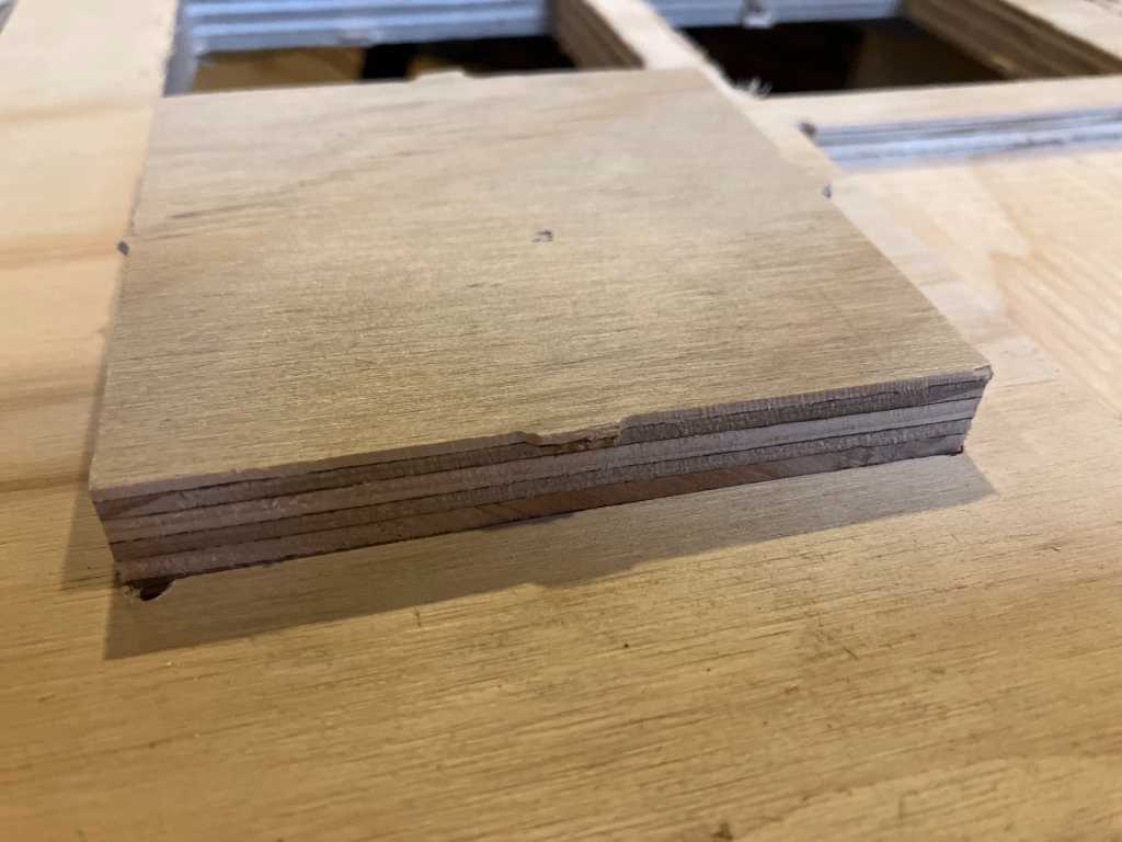
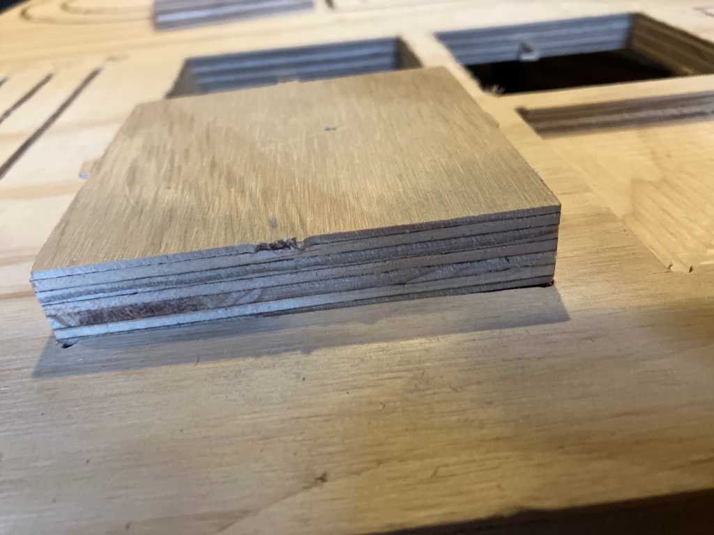
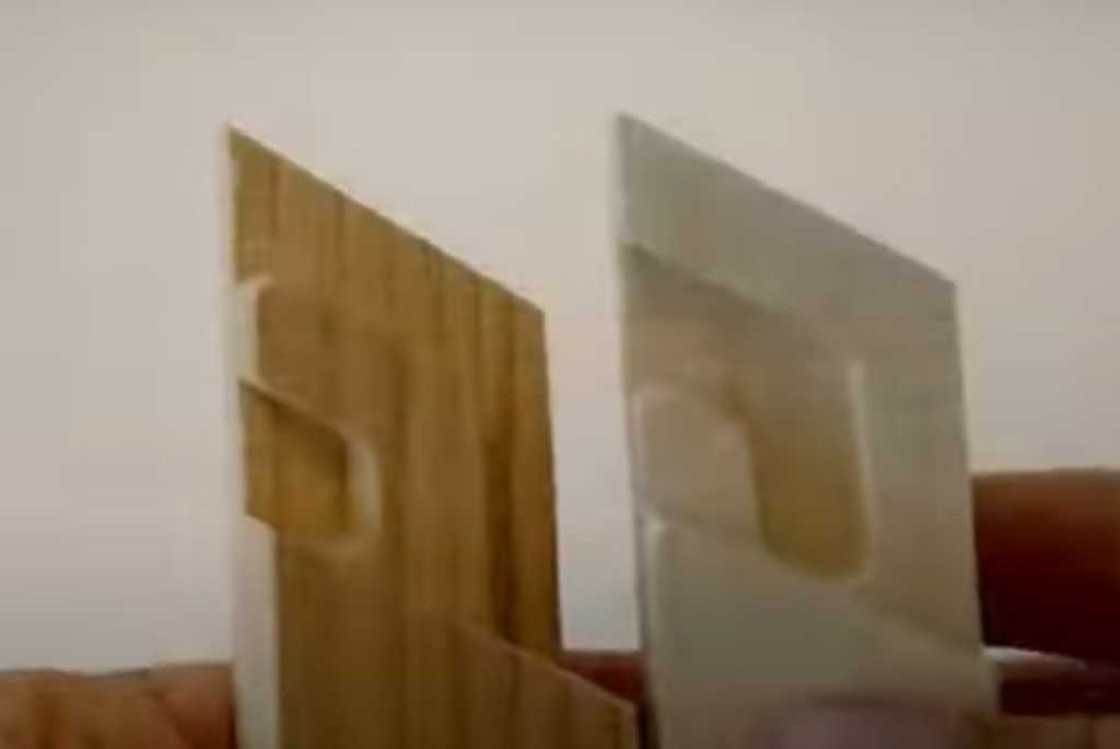
Dog bone vs t-bone:
This dog bone and t-bone test is just to get a better feel about how they look like :-)
The end result:
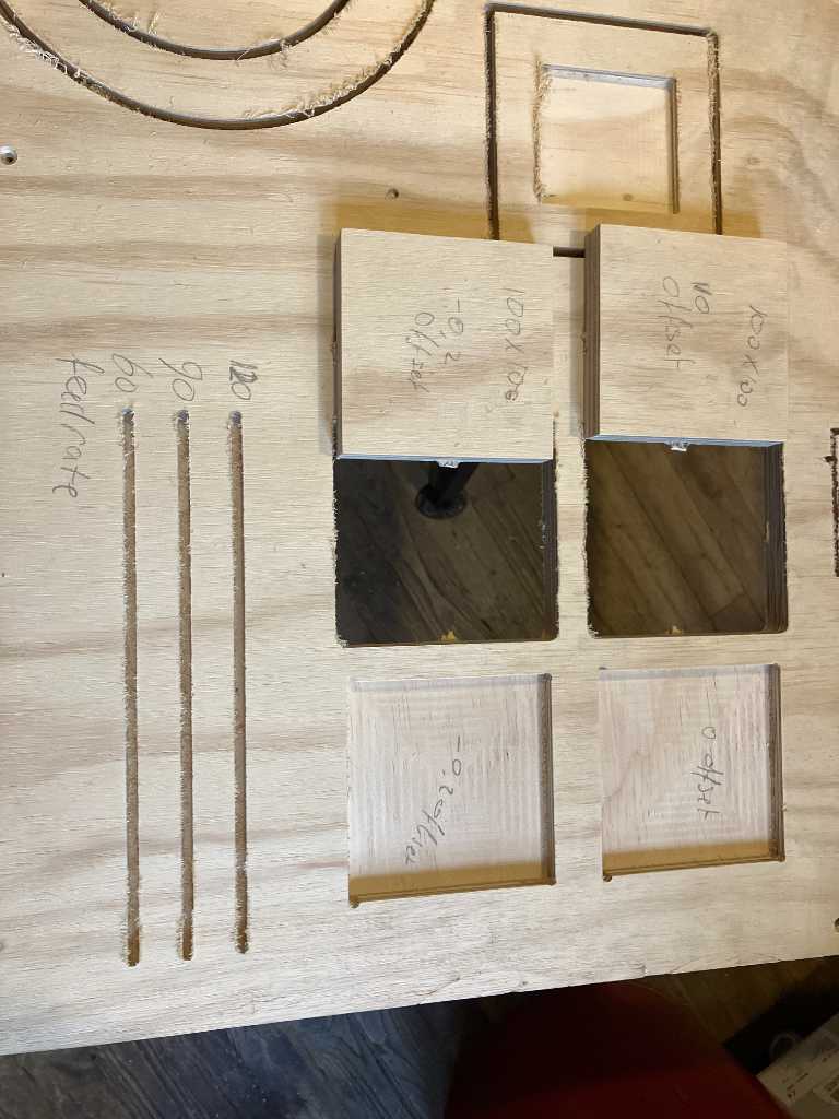
100x100mm no offset in 100x100 pocket does not fit:
With -0.2 offset both on contour as well as pocket fits like a puzzle (no press fit though):
No-offset contour in -0.2 offset pocket is press fit:
So theoretically if you’d do a -0.1 offset on both contour as well as pocket, it should be a pressfit too.
But when rotated 90 degrees it doesn’t fit:
so that means in X and Y directions the width is different. Let’s check:
| no offset countour | -0.2 mm offset contour |
|---|---|
| X width: 99.98 mm | X width: 99.53 mm |
| Y width: 99.70 mm | Y width: 99.30 mm |
| width delta: 0.28 mm | width delta: 0.23mm |
| diagonal 1: 140.76 mm | diagonal 1: 140.06 mm |
| diagonal 2: 140.93 mm | diagonal 2: 140.19 mm |
| (calculated diagonal: 141.42 mm) | |
| diagonal delta: 0.17 mm | diagonal delta: 0.13 mm |
| no offset pocket | -0.2mm offset contour |
|---|---|
| X width: 99.65 mm | X width: 99.98 mm |
| Y width: 99.64 mm | Y width: 99.80 mm |
| width delta: 0.01 mm | width delta: 0.18 mm |
So that means there a bit of a skew in the machine, but not too much.
So that concludes the group assignment. Interesting stuff!!
Individual assignment
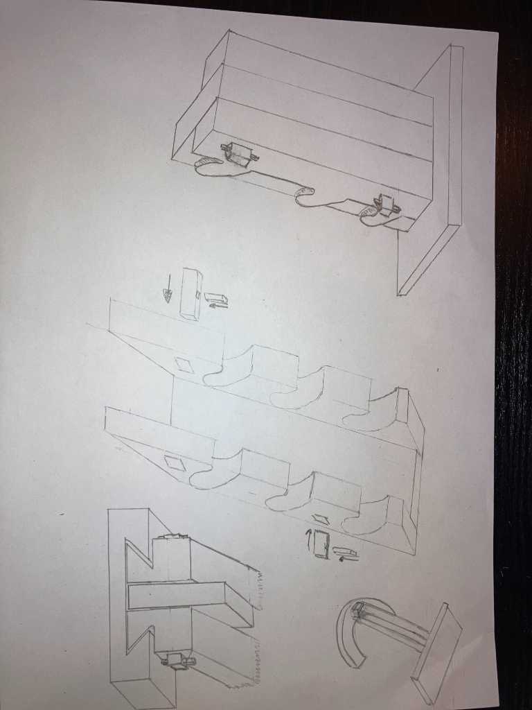
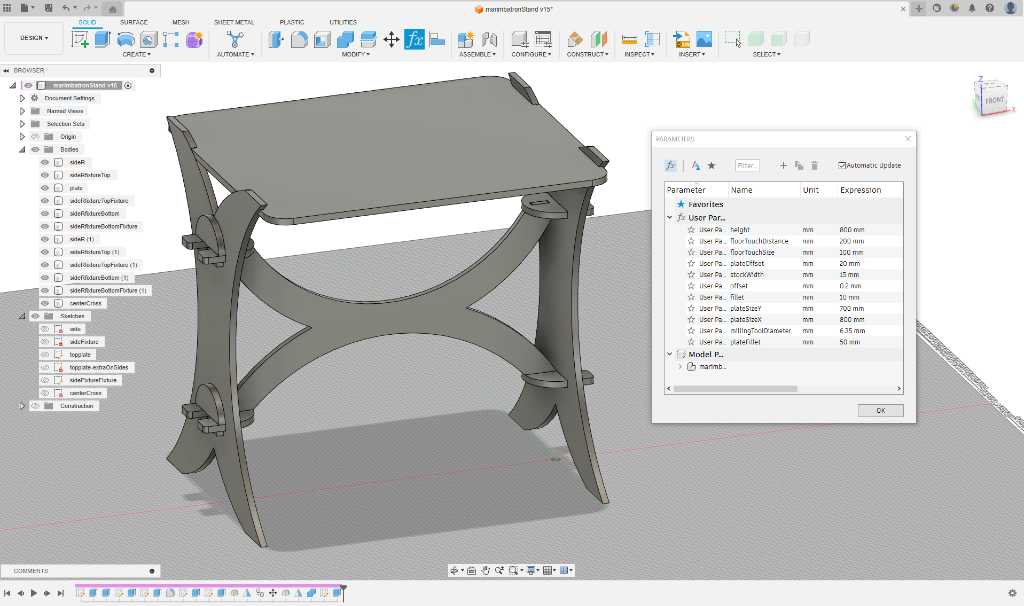
This is the sketch of the Marimbatron table that I hope to be able to make this week.
I watched the very interesting Tsugite video. One of the nice things is the non-ortogonal angle of intersection joint, pictured below. Maybe I can use this:
non-orthogonal angle of intersection - from Tsugite video
Available CAM software at Fablab Enschede:
- carbide Create
- Fusion 360
- Meshcam
Software to operate the Shapeoko:
- Carbide Motion
Shapeoko Pro XL using Fusion 360 (something small)
I’ve never used Fusion 360 before to create the toolpaths for CNC machining. I watched this video as introduction: milling on the shapeoko using Fusion360 youtube introduction video made by Ruckus Workshop.
Below is the workflow that I took from this video, on how to use Fusion 360 to create toolpaths for the Shapeoko CNC.

One time setup
go to Manufacture
Manage -> machine library -> add new (+ icon) -> milling
Add carbide3D Shapeoko XXL -> download most recent from cam.autodesk.com and search Carbide.
Edit the Machine configuration:
- Dimensions
- change dimensions to 838 mm x 445 mm x 100 mm (check if this height is correct!)
- Capabilities
- milling
- max feedrate 2540 mm/min
- workpiece
- 800 mm x 400 mm x 88 mm
- Kinematic -> no changes from default
- Spindle -> no changes from default
- Machining Time -> no changes from default
- Coolant -> no changes from default (nothing checked)
- Post processing
- Number of work Offsets 100
- Post location Browse -> select the post processor downloaded from cam.autodesk.com previously
- Post Processor Carbide3d.cps
- Multi axis -> no changes from default
Setups
Each setup is a specific orientation how your milling. Add new setup from the menu:
- Setup -> new setup
- First tab
- Select Shapeoko machine
- operation type = milling
- Orientation = select Z axis/plane & X axis
- this allows you to use Flip Z Axis on another setup so you can mill both sides of the stock
- Stock Point –> important to get this right!
- Click Box Point and select top left botfront corner of the design.
- This will be your zero position
- Y should be going to the back of the machine and X should go to rightside of the machine.
- Model -> select the body you want to mill.
- Second tab: stock
- Check the dimensions of the stock that needs to be used
- Dimensions show the dimensions of the body
- If stock size is equal to dimensions of body to be milled:
- Set Mode to Relative size
- Set Offsets to 0
- If the stock size is bigger
- Set Mode to Fixed size
- Enter size of the stock
- Or try any of the other modes
- Third tab: post process
- Already configured in the machine, so no changes
Click OK
Operation
In the menu there are two options to add milling operations: 2D and 3D. 2D is also used for operations where multiple depths are involved. But 3D is specifically if you want curved mills. For example contours, scallops, ramps, etc.
Click 2D and select the operations required:
- 2D contour
- Usage
- Contour the perimeter or inside perimeter of something
- Cut a shape out of something -> important: Tabs are required! Have to be manually set up!
- First tab: Tool
- Select Tool (required for every operation)
- Download the tool libraries of the tools you have here:
- carbide3D
- amanatool
- whitesiderouterbits
- These are already set up to use the correct feeds and speeds
- Download the tool libraries of the tools you have here:
- Change feeds and speeds if needed
- Select Tool (required for every operation)
- Second tab: Geometry
- Select the contour that needs to be milled. Select the bottom contour if you want to mill something out.
- Enable tabs checkbox so it creates tabs
- Third tab: Heights
- Clearance height -> from rectract height -> offset 5mm
- Top height -> stock top -> offset 0mm
- Bottom height -> selected contour(s) -> offset 0mm
- Fourth tab: Passes
- Select Multiple Depths checkbox -> don’t cut something out all in one go!
- Stepdown is same thing as depth of cut. So set Maximum Roughing Stepdown according to the Shapeoko table of the specific Tool and specific material.
- All other settings leave to default.
- Some of these settings might be tweaked to get faster speeds or better finish
- Select Multiple Depths checkbox -> don’t cut something out all in one go!
- Fifth tab: Linking
- Select Keep Tool Down (otherwise tool will fully retract each pass and then down again)
- No other changes from default.
- Some of these settings might be tweaked later. E.g. Lead-in and transistions (don’t cut into material of neighboring cuts)
- Click OK.
- Usage
It’s now going to create the toolpaths. When done, you’ll see them in the design.
- 2D Pocket
- Select tool
- Select bottom face of the area you want to pocket
- Third tab: Heights
- Clearance height -> from rectract height -> offset 5mm
- Top height -> stock top -> offset 0mm
- Bottom height -> selected contour(s) -> offset 0mm
- Fourth tab: Passes
- Passes
- Maximum Stepover
- how much it overlaps previous toolpaths.
- Affects finish and how much load you put on the bit.
- Too high will break the bit
- Rule of thumb: 1/2 of the diameter of the bit
- e.g. 3mm for a # 201 bit.
- Maximum Stepover
- Select Multiple Depths checkbox -> don’t cut something out all in one go!
- Stepdown is same thing as depth of cut. So set Maximum Roughing Stepdown according to the Shapeoko table of the specific Tool and specific material.
- e.g. 1mm for a # 201 bit.
- Stock to leave -> uncheck.
- Allows you to leave some material so that another operation can clear that remaining material. This will give a better finish.
- When Stepover and Multiple Depths is set correctly, this is usually not needed.
- All other settings leave to default.
- Some of these settings might be tweaked to get faster speeds or better finish
- Passes
- Click OK
It’s now going to create the toolpaths. When done, you’ll see them in the design.
- 2D Adaptive Clearing
- difference with 2D pocket is that adaptive clearing is designed to put less stress on the tool. Angles that it comes in with the tool with angles that put less load on the tool.
- Select a bottom of a pocket
- Check heights
- Fourth Pass: Passes
- There a new option called Optimal Load
- This is similar to stepover amount, but the amount will vary to reduce overloading the tool
- Put a number in here that is similar to stepover (e.g. 1/2 of diameter of end mill)
- Uncheck Stock to leave
- Select Multiple Depths and set that up
- Click OK
It’s now going to create the toolpaths. When done, you’ll see them in the design.
Right click the toolpath in the browser and click Simulate. You can now see the tool moving.
Right click the toolpath in the browser and click Machining time. You will now see how long this operation will take.
These things can also be done with multiple selected toolpaths, or select the whole setup, e.g. to see the total milling time and simulate it all.
Post processing (create GCode)
Highlight the operations you want to process (or select the whole setup).
Right click and select Post Process.
No changes to the Post Process popup are required. Click OK.
This will create a .nc file. This is a GCode file, similar to when you save from Carbide Create.
This .nc file needs to be loaded in to Carbide Motion and run this operation on the Shapeoko.
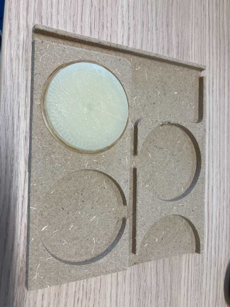
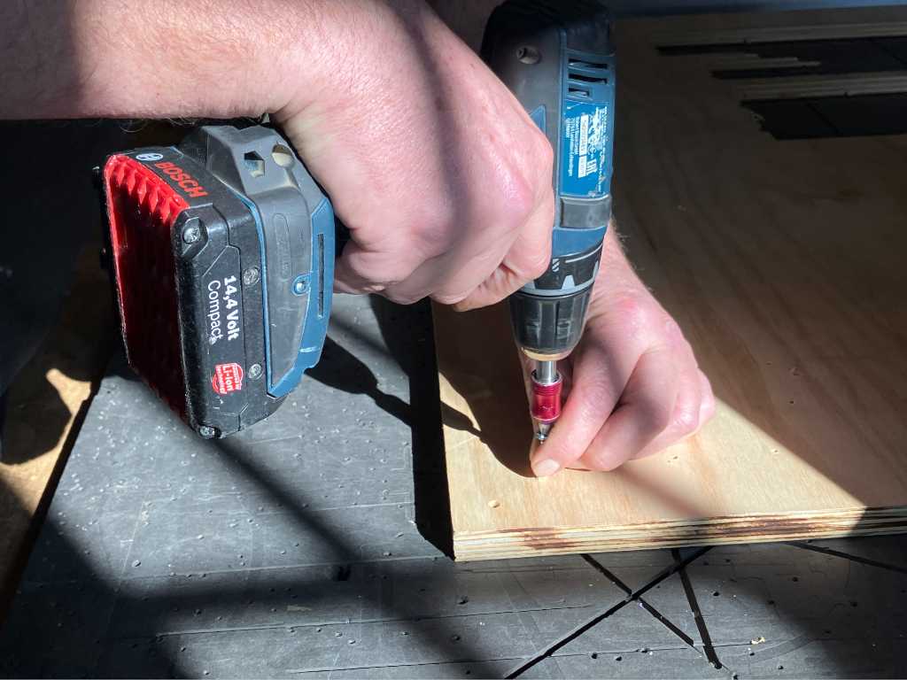
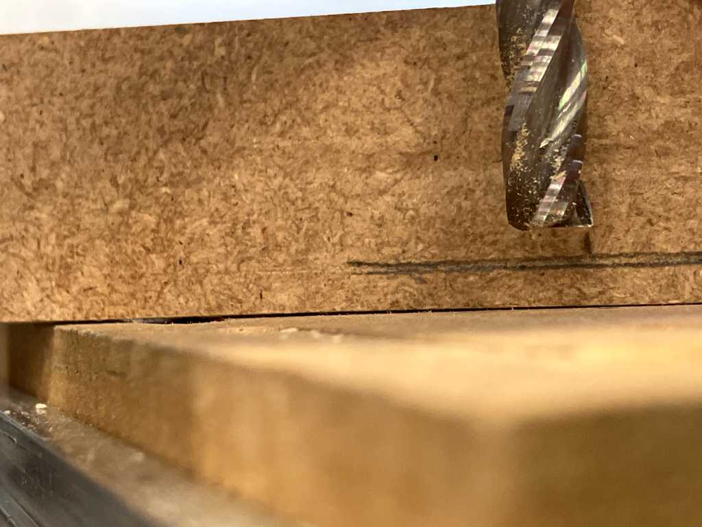
I used the prodedure above to mill a partial piece of the sensorfixture out of MDF as a test to see if a sensor fits and how the sizes look&feel.
I found out that some of the properties above are either not available anymore, or are relocated to a different tab. Some properties I couldn’t find, for example setting stock size. At a certain point, I should refine the procedure above. But not now.
I used the following settings:
- 1/4” #201 flat end mill
- 18.000 RPM
- Feedrate 1524 mm/min
- Plunge rate 406 mm/min
- Retract offset from stock top: 5 mm
- Stepdown: 2 mm
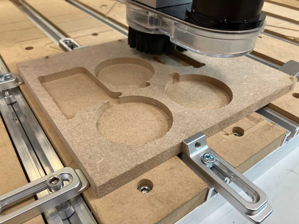
Thats a good fit. However the left long edge feels a bit small and fragile. Also, there’s hardly any space for cabling. I think I have to redesign this, but the CNC milling worked!
Design in fusion (something big)
I want to create a table that I can use to put my Marimbatron on. Ideally the height should be 85cm. This is a pretty standard height for Marimbas.
Total size of a 4 octave Marimbatron is around 700 x 800mm (L x W). So that should fit on the top plate.
I don’t want to use any glue so I’ll have to think about joineries. I designed my CNC job in Fusion, parametrically of course.
Fusion 360
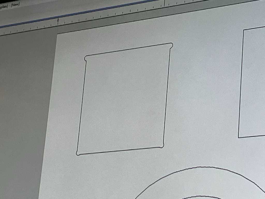
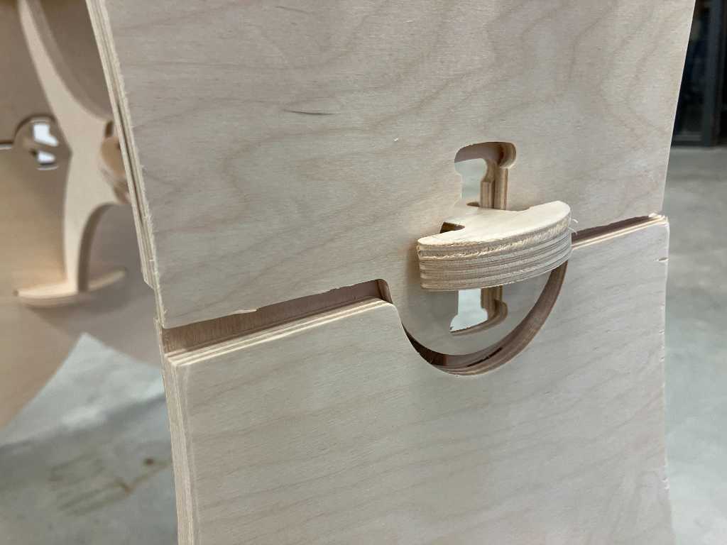
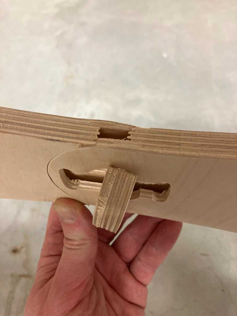
Some closeups with different dimensions, a check that the parametricallity (is that even a word?) works as expected. I used T-bones in a way that it is hidden as much as possible:
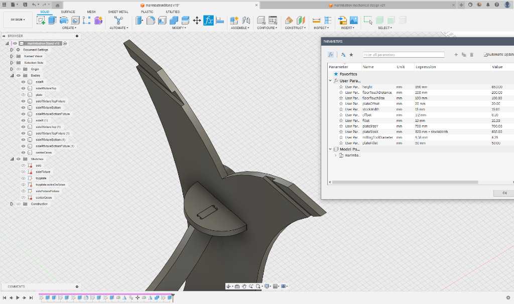
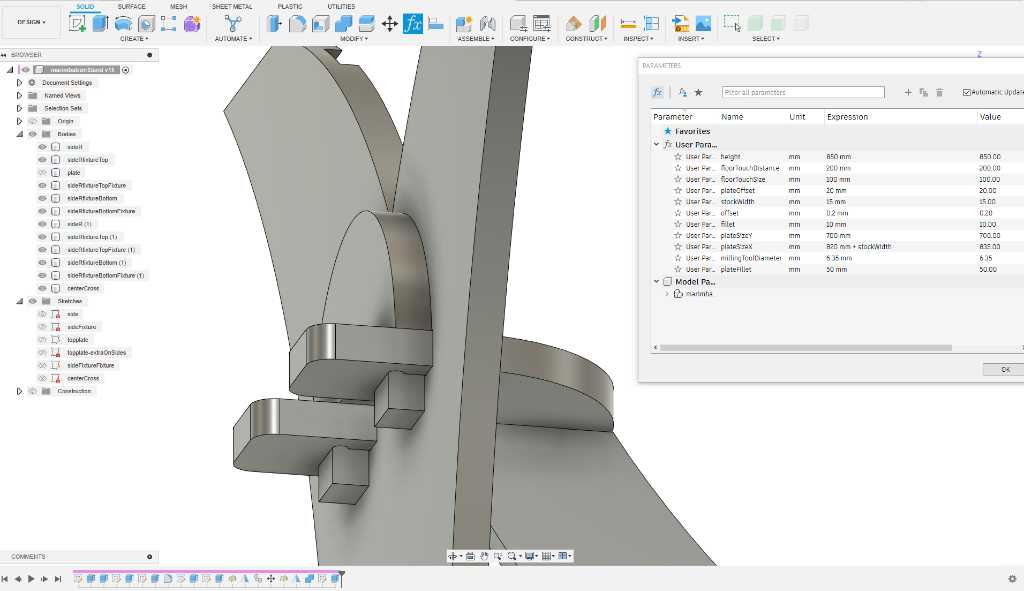
I’m going to mill this on our Shapeoko 3 XXL. that means that my stock size is limited to about 800x800mm. But my total size should be larger. So I’ll have to use some joints. I looked up the incredible fablabifurniture.org and found a joint that I think will fit my purpose. Number 14: the Detachable Lengthening With Key.
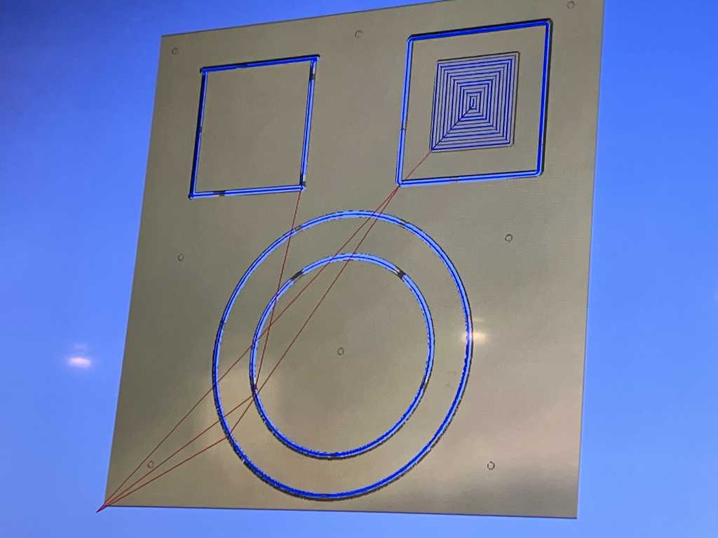
Carbide Create (toolpath creation)
I downloaded the DXF files and imported them into Carbide Create, the vector editor tool for Shapeoko. I had to merge the joint into my design, so hopefully this will work.
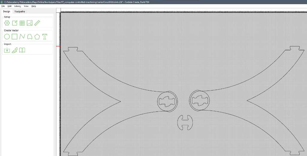
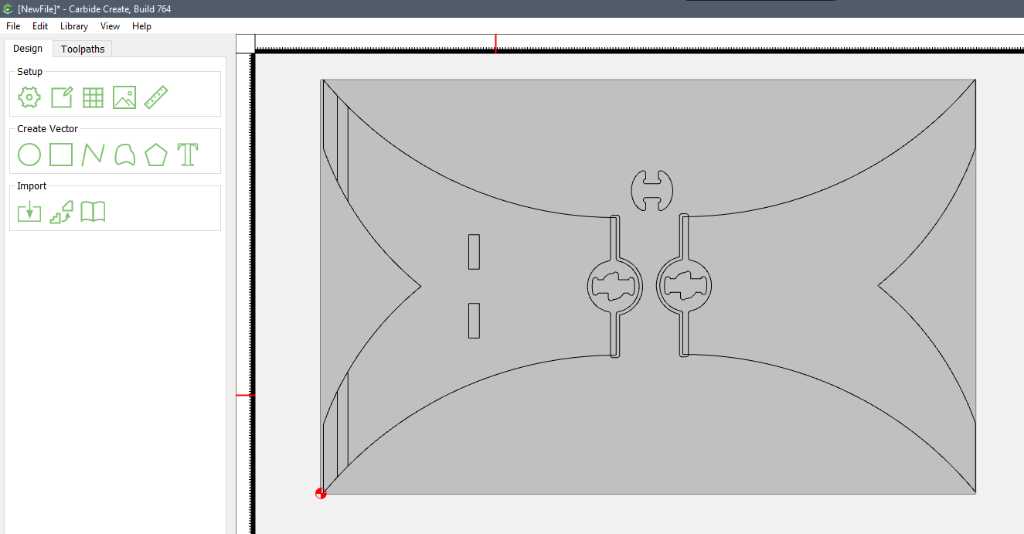
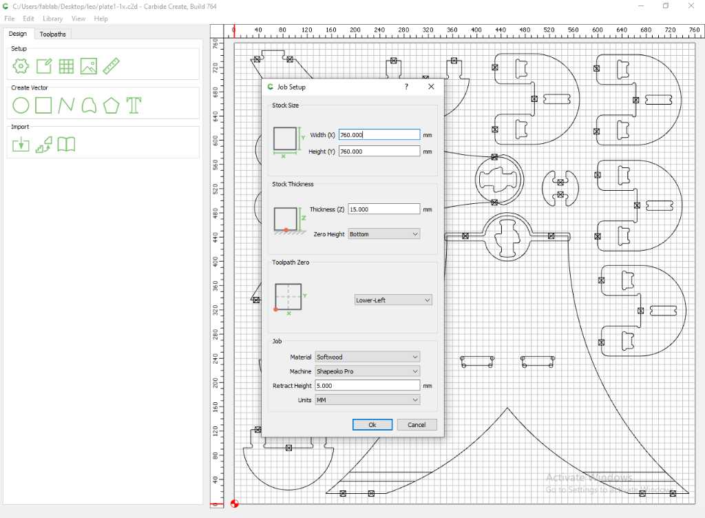
Next I added all designs onto plates of 76x76cm and added all the tabs, pocket toolpaths and contour toolpaths.
I used the following settings:
- 1/4” #201 flat end mill
- 18.000 RPM
- Feedrate 1905 mm / min
- Plunge rate 381 mm / min
- Retract offset from stock top: 5 mm
- Stepdown: 1.524 mm (Shapeoko default)
- Stepover: 10% (Shapeoko default)
- Tabs: 8 mm (W) x 5 mm (H)
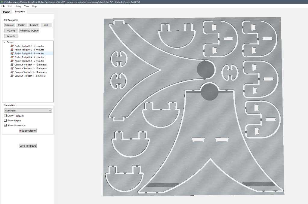
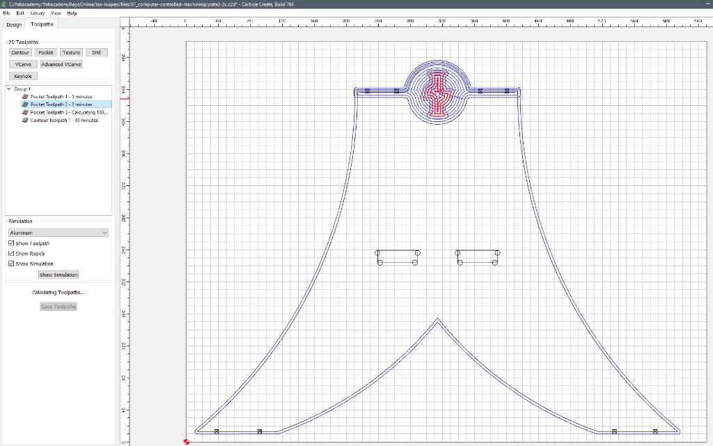
Here you can see Carbide Create V7 where I created 4 toolpaths. 3 are pockets, the other the contour. The CNC maching will adhere to the order of these toolpaths. Also the tabs I placed manually are indicated with black squares with a cross. You can also see that I’ve added T-bones for the inner pocket, because I forgot to add them in my Fusion design.
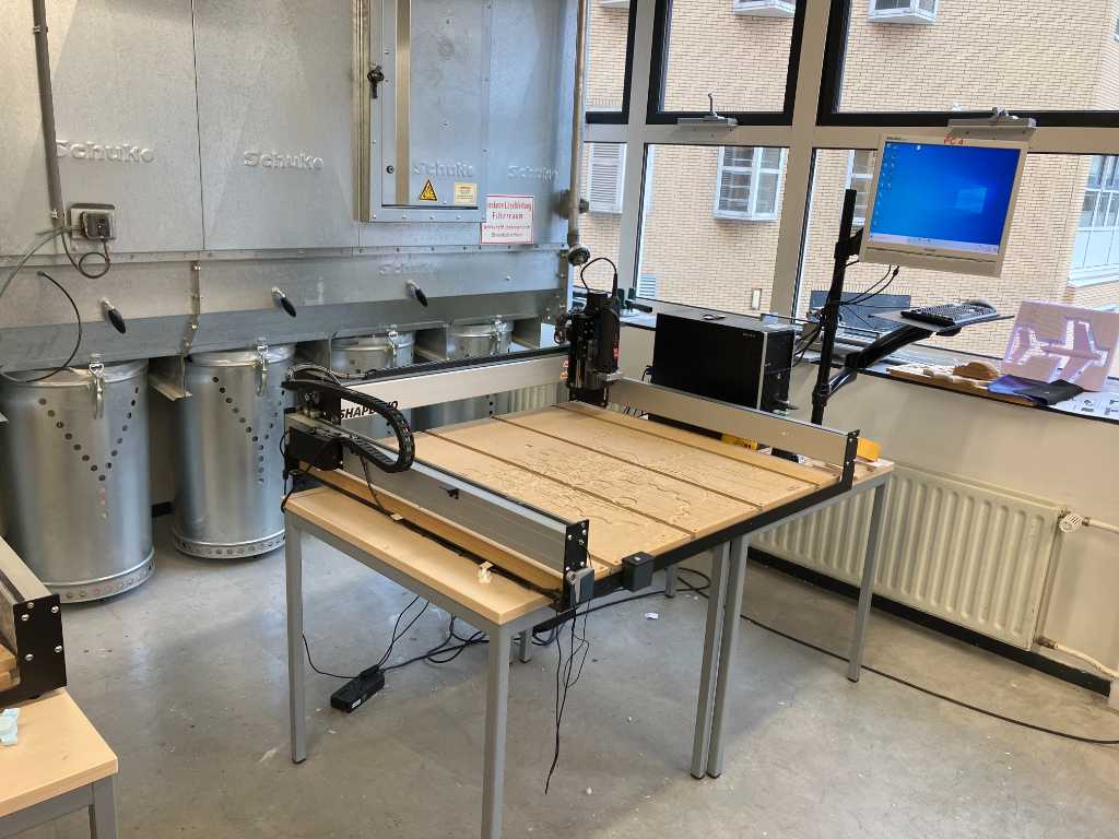
Shapeoko 3 XXL
I went to the lab of Industrial Design where they have a Shapeoko 3 XXL. I have some 18 mm plywood stock here that I want to use.
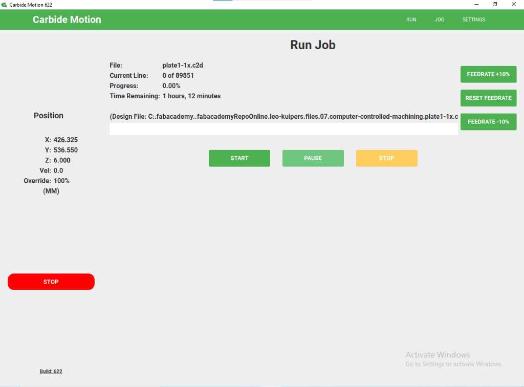
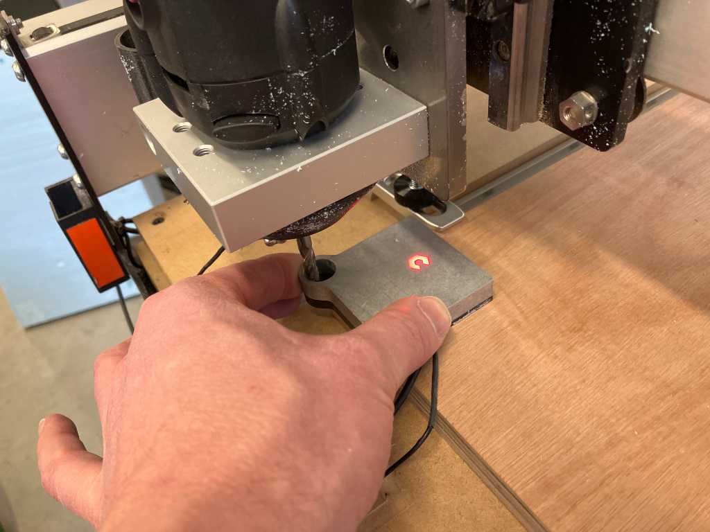
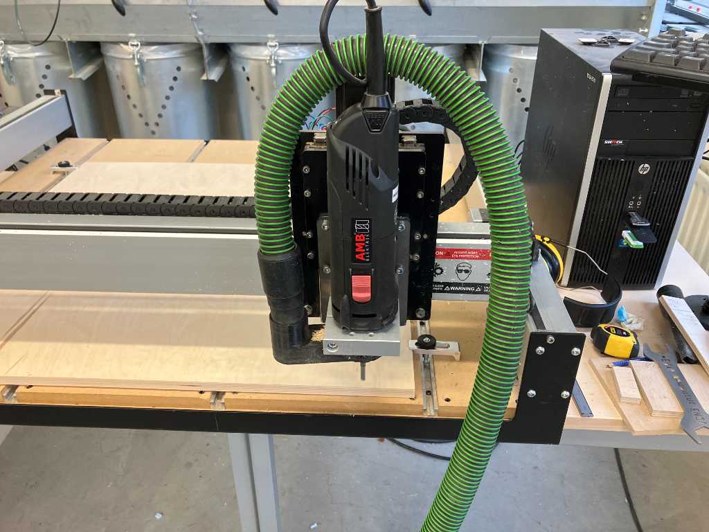
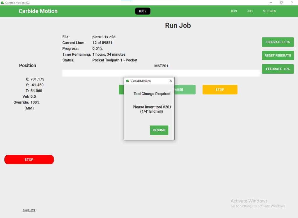
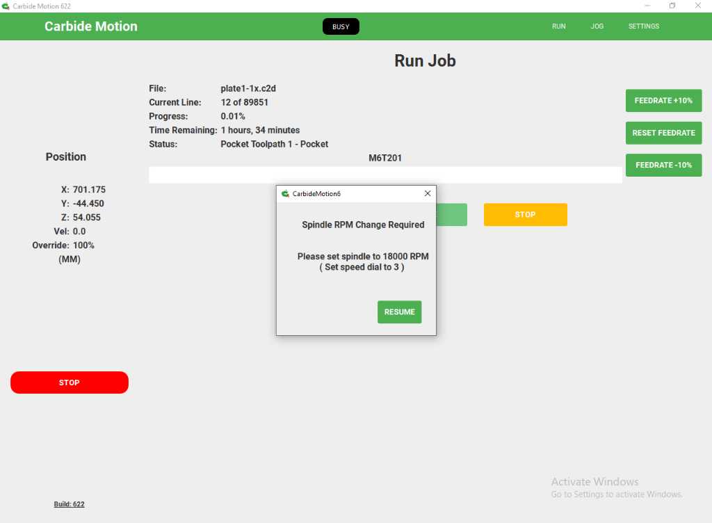
The Shapeoko is operated using Carbide Motion. Here are some important screenshots:
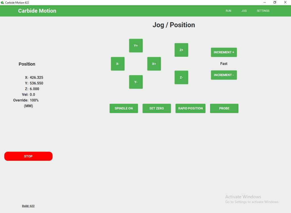
The BitSetter is used to measure the length of the tool installed.
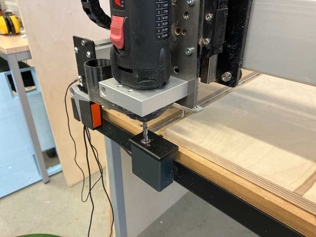
The BitZero is used to zero X, Y and Z. The Z is zero’d on the workbed (not on stock top).
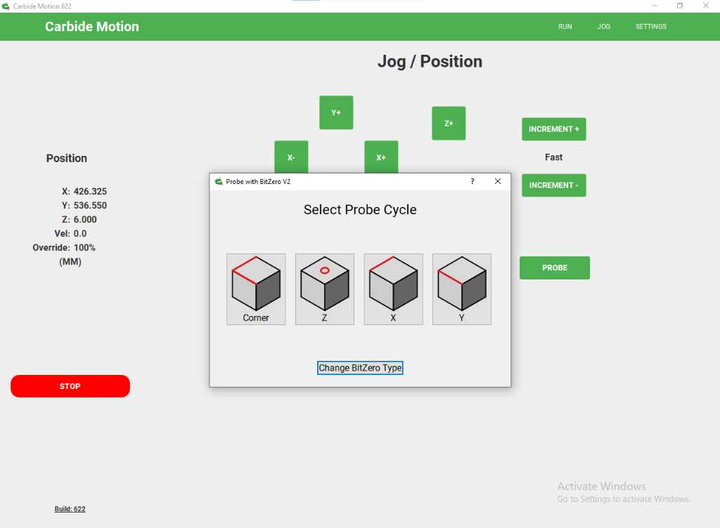
Next the vacuum hose is attached and we can start milling.
Carbide Motion guides you through the steps:
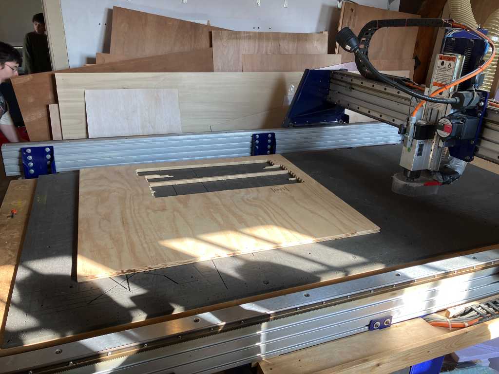
The stock is held into place using removable fixtures. They are quite easy to use. I first mill a small piece of my design. To test the machine and to test the offsets that I applied (0.2 mm):
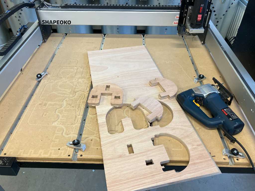
So this went well. The offset is good. However, I don’t have enough 18mm so I had to go back to Fusion, set my stock size parameter to 15 mm and re-do the toolpath generation.
Back to the milling again, and after a few hours (and sanding of course):
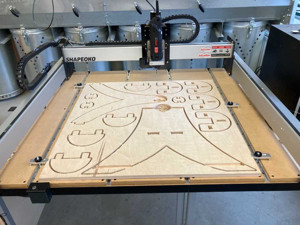
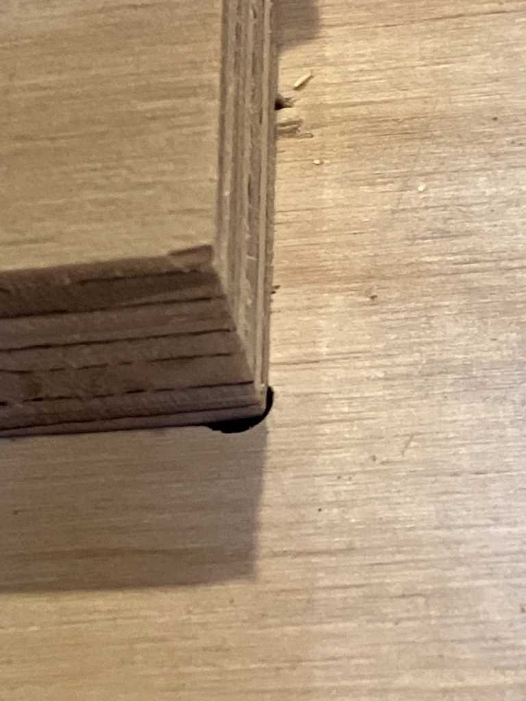
This turned out to be a very unstable table… 2 things that failed:
I made a mistake adding the joint to my Fusion-designed vector file. This causes an offset of about 5 mm. #fail
Secondly, I noticed there was something wrong with the workbed of the machine.
I marked the height of the end mill on the North side:
And then jogged to South West, to the area where I zero’d my Z.
Auch. that explains what happened. The workbed isn’t perpendicular to the spindle! This is about 3 mm. I created the lapjoints here, so they total to about 5 mm offset. Not good. #fail
But still, this was a very fun week full of stuff I didn’t do before. I’m happy.
Link to repo
What I learned this week
Successes
I looked forward to this week. Especially because CNC milling isn’t something I do a lot. Although I knew the specific terms, I couldn’t really say that I was able to do more than just “follow the default”. I feel much more confident about all the specifics now, which is exactly what I hoped for.
I designed a table in Fusion and had to change parameters a couple of times. The auto-applied constraints sometimes didn’t do what I wanted, but in the end the parameters worked out nice!
I also paid a lot of attention to make T-bones in a direction that will make them invisible after putting the table together. And that worked out nice as well.
Fails & Fixes
I only made 1 real mistake. I should have tried to apply the downloaded joint in Fusion. I could’ve noticed my mistake immediately. But because it was late I decided to take the shortcut and use Carbide Create to make the joint. And did it wrong…
The other big fail was the machine. The non-perpendicular workbed caused too much stock to be milled away. Unfortunately, but now we know what has to be done on this machine.
Remember this for next time
CNC milling is fun, but takes lots of time. And I mean lots.
Various
Interesting resource on Feeds and Speeds here on precisebits.com.
Hardness of wood is measured using the Janka test