pressure sensor
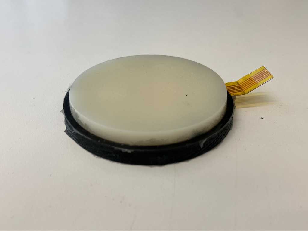
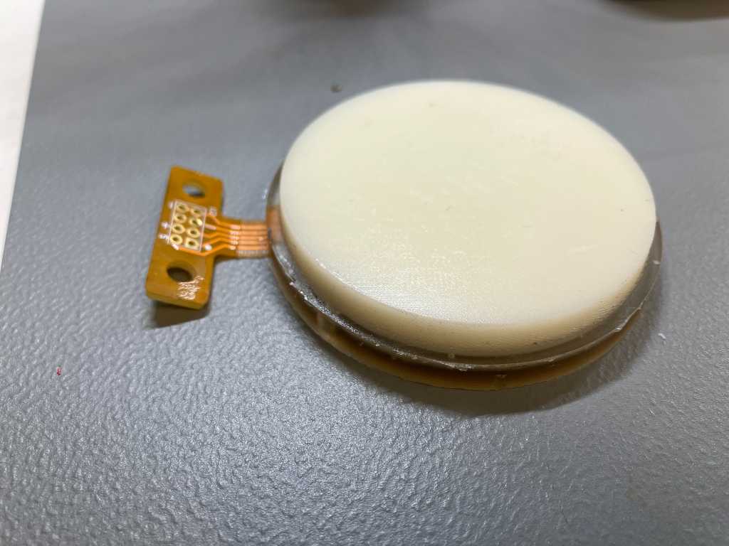
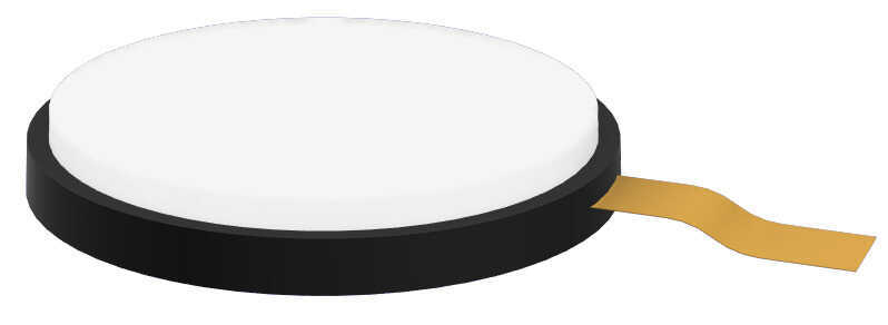
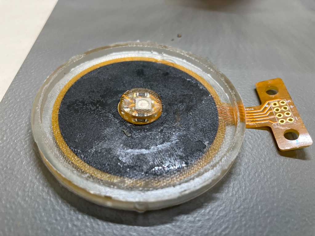
Hero shot
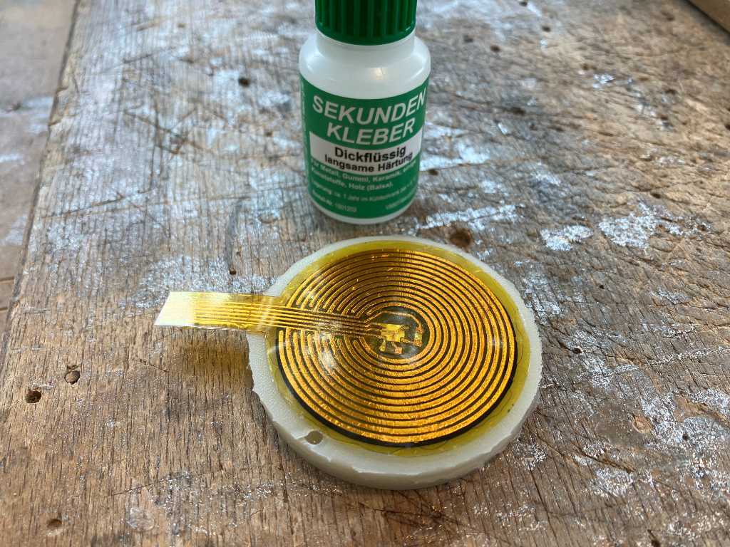
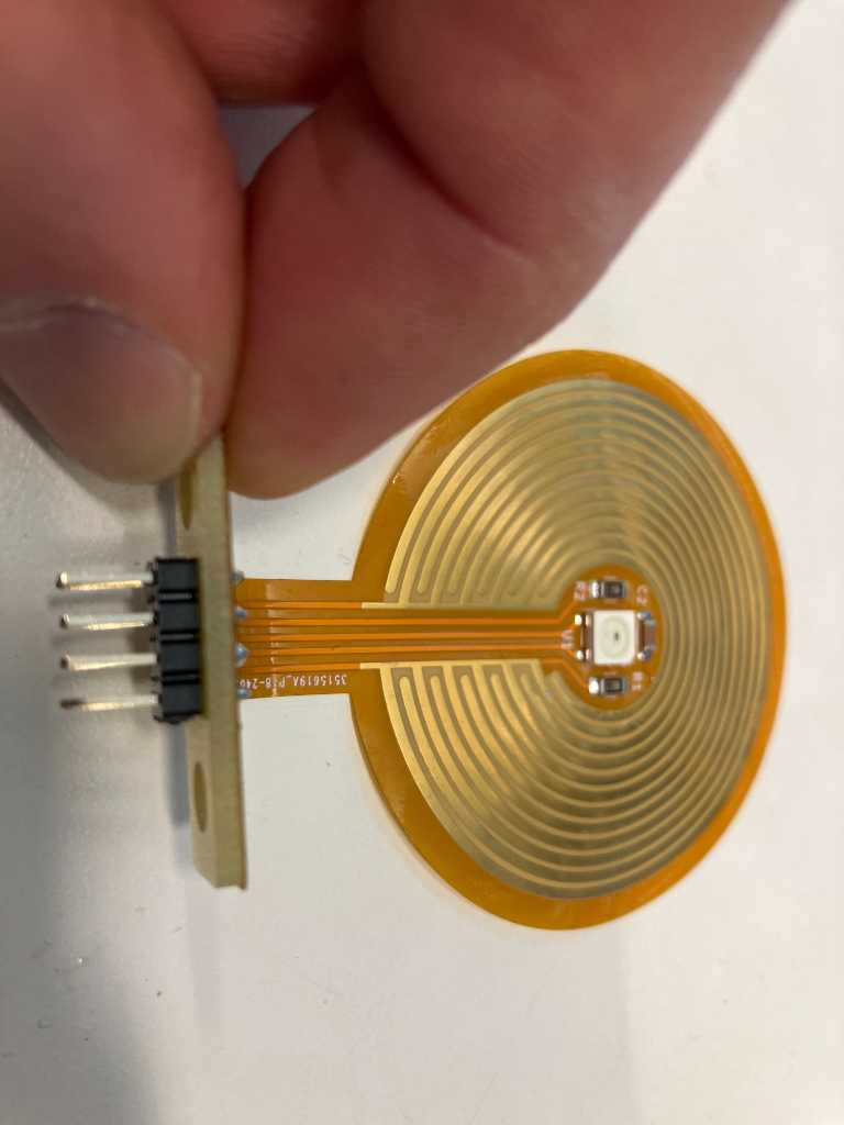
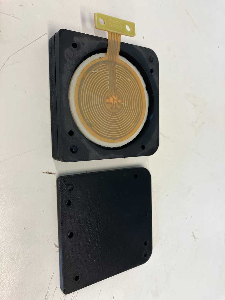
With self-made flex PCB:
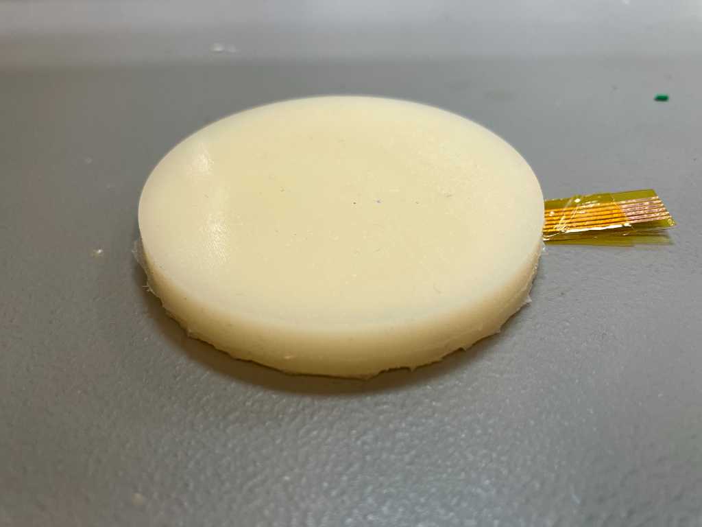
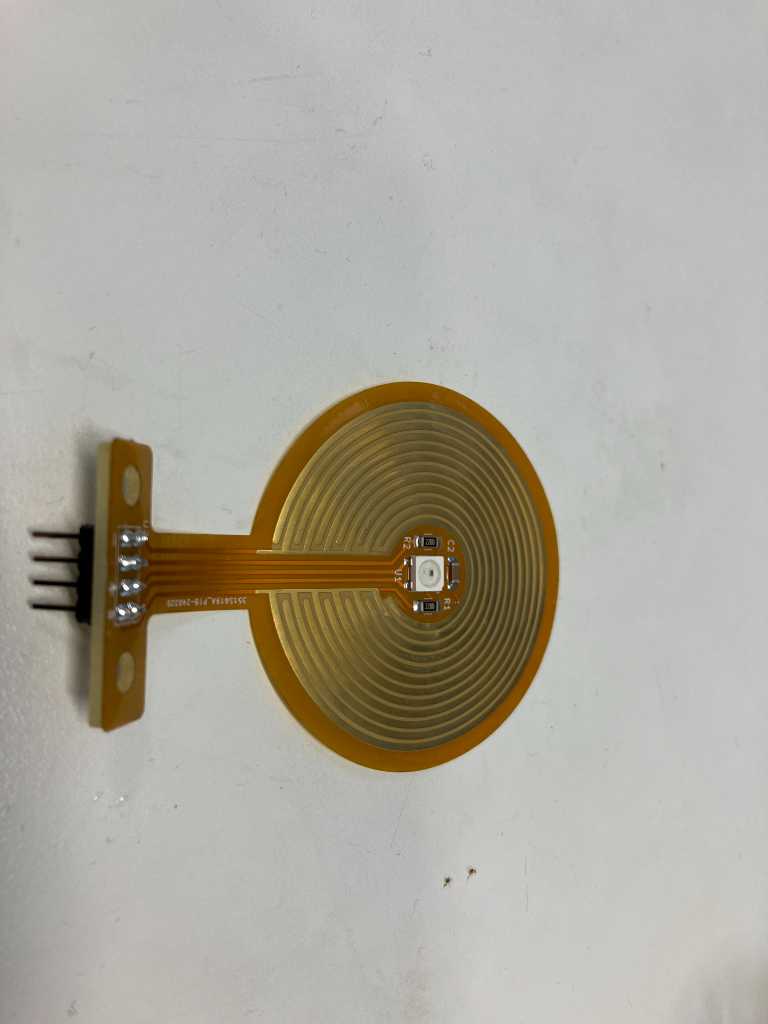
With final flex PCB:
theory
I’m going to need a pressure sensor. I will have to make my own because I need a specific size and I need a lot (76 in total) so better make them as cheap as possible.
There are different ways to create pressure sensors. So far I’ve found: - Resistive pressure sensor - e.g. velostat or linqstat: squeezing it will reduce the resistance (called piezoresistivity) - Capacitive pressure sensor - Piezoelectric sensors - Smart fabric - e.g. Keith McMillen Boppad. This turns out to be a form of resistive fabric.
piezoelectric
I own a Roland V-Drum digital drumkit. The sensors of the pads are piezoelectric. This works great, but the downside is that there’s a lot of crosstalk. Meaning when one pad is hit, the sensor of other pads vibrate as well, so they get triggered too.
But there must be a reason why they still use these sensors. I think this has something to do with speed. I believe piezo elements Are capable of measuring more quickly than the other technologies.
I want to give this a try. See if crosstalk is really an issue.

smart fabric
I owned a Boppad a while ago and it was really responsive and meant to be used with both sticks and hands. There was no noticeable crosstalk. So I investigated what is used in this device.
BopPad takes advantage of Smart Sensor Fabric Technology from BeBop Sensors, a leading supplier of fabric sensors & winner of the 2015 Frost & Sullivan Technology Innovation award. At the core of BopPad is a single large sensor made from the 8th generation of BeBop’s Smart Sensor fabric. BeBop develops sensors for OEM clients in Automotive, Sports & Fitness, Safety and Consumer Wellness.
From <https://www.kickstarter.com/projects/kmi/boppad-smart-fabric-drum-pad-from-keith-mcmillen>
a unique and proprietary conductive material that changes resistance as it is compressed
From <https://www.keithmcmillen.com/labs/>
It uses piezoresistive substrate
So their “smart fabric” is piezoresistive.
These sensor locations are each sampled over one thousand times per second in order to capture information about the percussionist’s input and convert that into a standard MIDI over USB output.
From <https://patents.google.com/patent/US9721553B2/en?oq=9721553>
the responses of the sensors in arrays enabled by the present disclosure may exhibit variation relative to each other. According to some implementations, calibrated sensor data may be stored (e.g., in memory 407 of processor 406) representing the response of each of the sensors. Such data may be used for ensuring consistency in the way the sensor outputs are processed and/or used to represent applied forces. During calibration, the output of each sensor (e.g., as captured by ADC 404) is measured for a range of known input forces. In this way, a set of data points for each sensor is captured (e.g., in a table in memory 407) associating ADC values with corresponding forces (e.g., weights in grams or kilograms). The data set for each sensor may capture a force value (or an offset value) for every possible value of the ADC output. Alternatively, fewer data points may be captured and the sensor circuitry may use interpolation to derive force values for ADC outputs not represented in the data set.
From <https://patents.google.com/patent/US9721553B2/en?oq=9721553>
And a microcontroller samples the sensors, does some analog-to-digital conversion and voila.
According to some implementations, shielding from electromagnetic interference (EMI) is provided to prevent stray fields from affecting performance. Such stray fields might be due, for example, to power grid 60-cycle hum, nearby wireless devices, capacitive coupling between the user’s hands and the printed traces, etc. The EMI shield could be provided in a number of ways. For example, for implementations in which the sensor traces are formed on piezoresistive fabric, conductive paint (e.g., nickel paint) could be provided on PET sheets above and/or below the piezoresistive fabric. The shielding might be combined with the diffuser layer discussed above (e.g., with the conductive paint on the other side of the diffuser from the fabric).
From <https://patents.google.com/patent/US9721553B2/en?oq=9721553>
Nice warning: EMI could be an issue.
a hysteresis scheme is implemented for hit detection because simply reporting high ADC readings might result in false triggers due to individual noise spikes. The scheme employs two thresholds: one for amplitude and one for duration. The amplitude threshold requires the ADC reading for a sensor to be equal to or greater than the offset value plus the threshold. If the magnitude of the ADC reading is great enough, this constitutes a peak and increments a counter that keeps track of the number of adjacent peaks. The duration threshold requires the number of adjacent peaks to be equal to or greater than the threshold. If the number of peaks that occur in a row is great enough, a hit is registered and the processor sets an internal flag in preparation to report this event.
From <https://patents.google.com/patent/US9721553B2/en?oq=9721553>
And they did a great job doing this.
resistive (FSR: Force sensitive resistor)
So this smart fabric is actually resistive. It’s actually a Force Sensitive Resistor (FSR). Devices with velocity sensitive pads from other manufacturers, like ableton Push and Novation launchpad pro, use carbon pills in rubber or silicone pads. These pills are conductive and have a resistive nature. So this is probably a good working and cheap solution otherwise they would have implemented a different solution. Because these manufacturers are quite high end.
Similarly, velostat or equivalent FSR material can be used. This is a sheet of plastic with carbon layer. So resistive and it’s resistance drops if your press on it. Due to required size of my pads I think I could make a resistive sensor out of this velostat material.
capacitive
Capacitive pressure sensors can be made out of two sheets of conductive material, e.g. copper tape with a dielectric material in between. The capacitance between the two parallel plates is inversely proportional to their separation distance.
I’ve read that these sensors tend to be very accurate but are prone to external electromagnetic interference. For example your hand close to the sensor might cause disturbances in readouts. That’s why they are especially suited for touchscreens. So they typically require more complex signal conditioning circuitry compared to other pressure sensing technologies, which can increase the overall cost and complexity of the system.
I’ve also read that it’s going to be hard to measure a lot of capacitive sensors as you can’t really multiplex the sensors due to capacitive and resistive influences from the multiplexer IC.
So this doesn’t seem to be an appropriate technology for my situation.
conclusion
So to conclude, my task will be:
Make my own piezoresistive sensor with e.g. velostat (polyethylene with black carbon), flex PCB (polyamide / kapton, e.g. DuPont Pyralux) in a polyurethane casting.
And also try of piezoelectric elements could be an option.
manufacturing
design
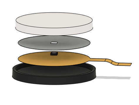
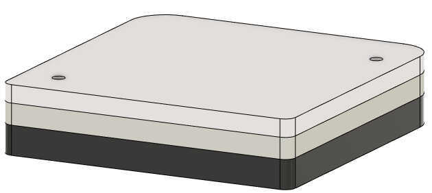
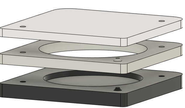
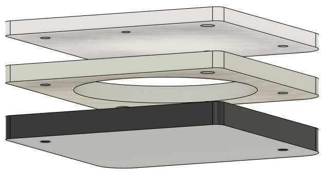
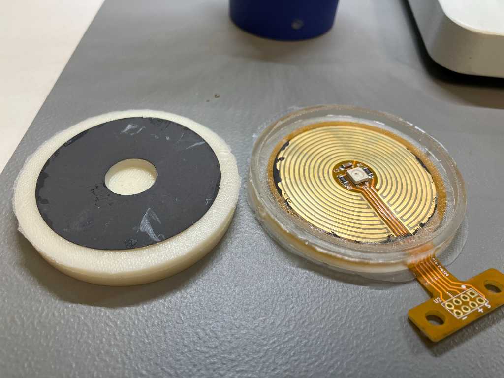
In this exploded view the layers are:
1. Top layer -> less flexible than base layer so sticks bounce better
2. velostat (piezo-resistive material)
3. flex pcb with traces and an RGB LED
4. Base layer -> flexible, gummy, should absorb impact energy so this is not transferred to other sensors (cross-talk)
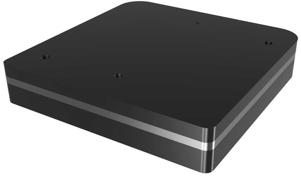
tooling
tooling of this first iteration consists of several separate pieces. The top layer will be a different shore (less flexible) than the base layer. So I first need to create the top piece. Next, I need to insert the flex-pcb and piezoresistive material and then overmold the base part. This needs to get stuck to the top piece really good. So to increase contact area, the sides of the top layer should be overmolded partly as well.
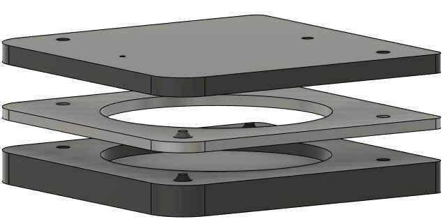
Here’s the fusion360 render of the top layer tool. For clarity I used different colors to easily distinguish the separate molds.
| top layer molds: 3 pieces | ||
|---|---|---|
 24-01-22-iteration1-topLayerTools.png) 24-01-22-iteration1-topLayerTools.png) |
 |
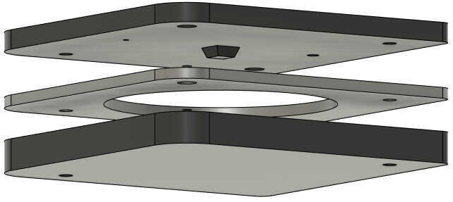 |
| bottom layer molds: 2 pieces | bottommold of top layer stays. | |
 |
 |
 |
manufacturing
moldmaking
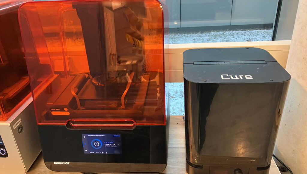
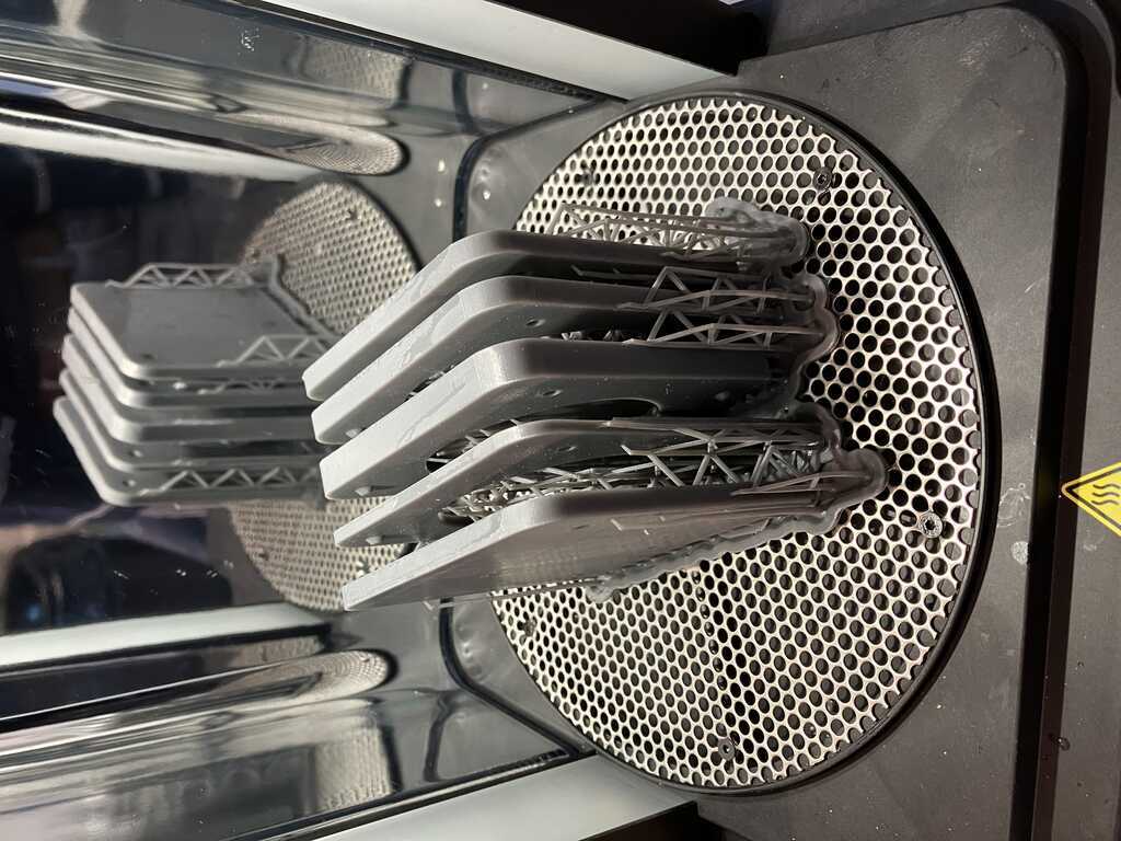
I want the final parts to be as smooth as possible, so I used a Formlabs with Tough 2000 material.
casting top layer
At the fablab Enschede we have several flexible polyurethanes:
| Product | Shore | mixing ratio | pot life | initial cure | full cure |
|---|---|---|---|---|---|
| Xencast PX30 | 30 Shore A very soft and flexible | 1:1 mixing by weight | 25 min | 24 hours | 7 days |
| Xencast PX60 | 60 Shore A medium flexible | 1:1 mixing by weight | 10 min | 1.5 hours | 7 days |
| Xencast PX90 | 90 Shore A semi-flexible | 1:1 mixing by weight | 5 min | 1 hour | 7 days |
| All manufactured buy Easy Composites. |
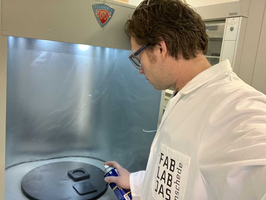
Mold release is going to be Smooth-on Unversal Mold release.
In my first iteration I’m going to go for shore 60A for the top layer and shore 30A for the bottom layer. I’m not going to put in a flexPCB yet because I haven’t designed and created it yet, but I’m going to use a piece of plastic sheet as try-out.
Iteratively measured: I need 30 ml material for the top part. And 20ml material for the bottom part.
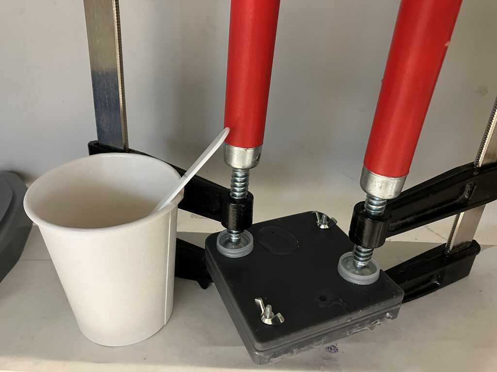
Adding the mold release (Smooth-on)
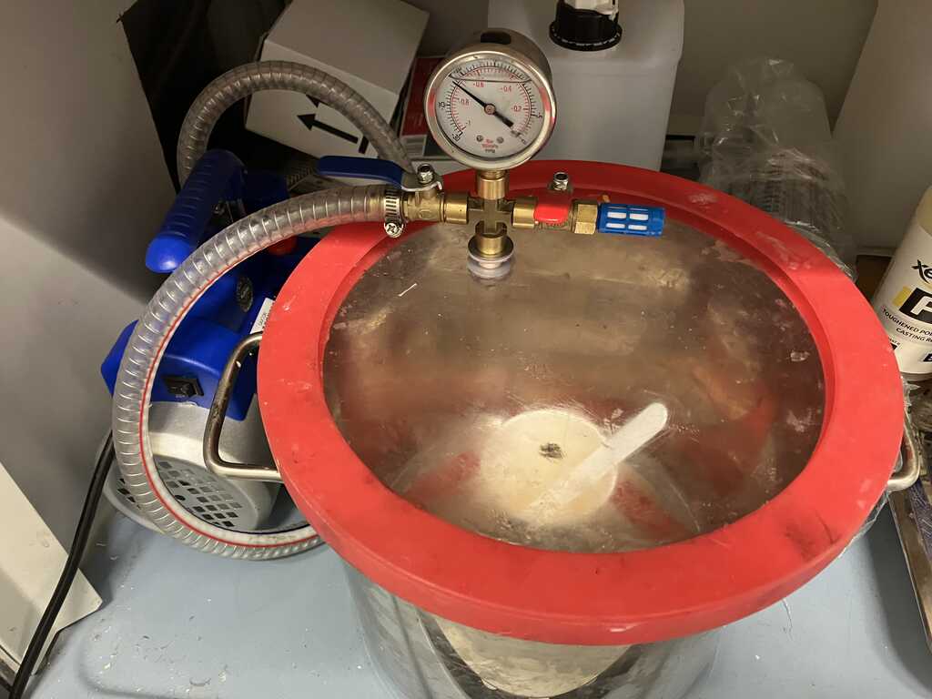
Degassing
after casting
Time to get it out of the mold:
cutting flex PCB and velostat
Next up is to try and create a first version of a flexPCB and cut a piece of velostat.
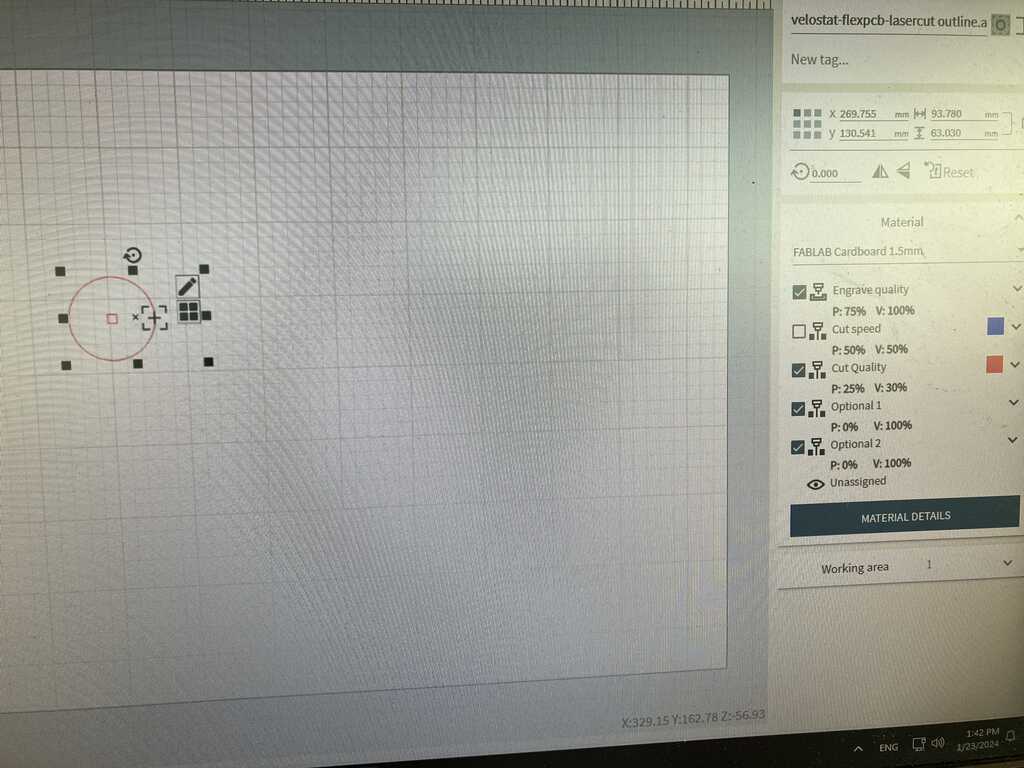
I’m cutting the velostat with our Trotec speedy 300 flex lasercutter. Settings took some trial and error to find out the values to cut through velostat. I started at:
- 1000 Hz
- power 25%
- Speed 30%
Eventually I ended up with
- 4000 Hz
- power 70%
- Speed 10%
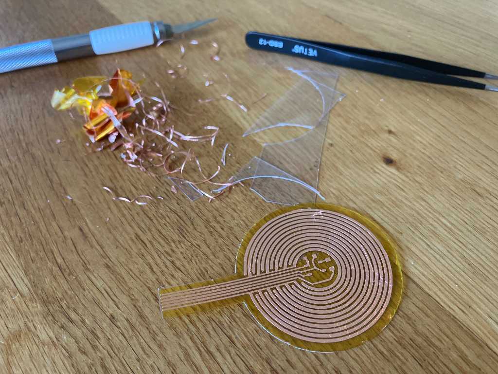
Now I have to create a flexPCB. But I don’t have the material for that and so I decided to quickly make something as a proof of concept.
So I created a DIY from several layers of Kapton tape and a conductive ink pen.
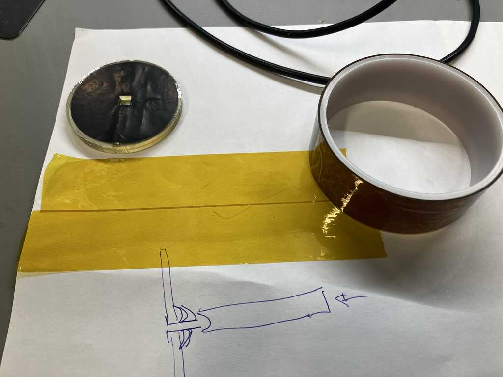
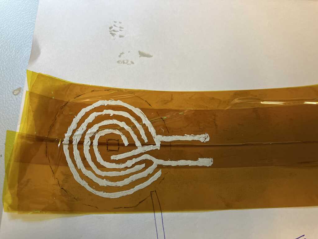
Cutting the Kapton tape worked with following settings: - 4000 Hz - power 80% - Speed 5%
I tried the working of my DYI flexPCB and the velostat:
This worked well. I don’t know if this is enough and if it reacts quick enough to catch mallets hitting it, but I’m satisfied.
casting bottom layer
Time to cast the bottom layer.
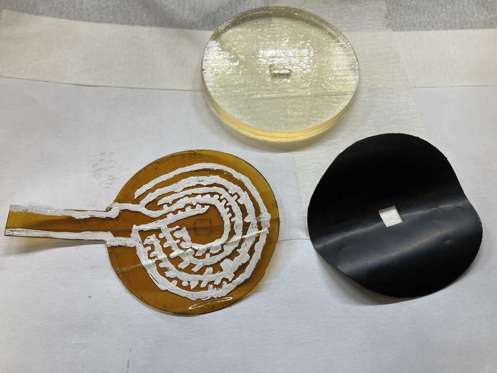
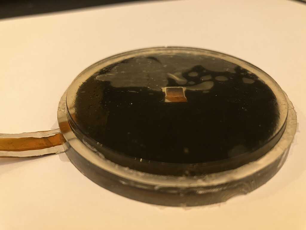
This came out well, except that the toplayer and bottomlayer didn’t mate. They were not attached to each other. Also some PU got between the flexPCB and the velostat, preventing it to work properly.
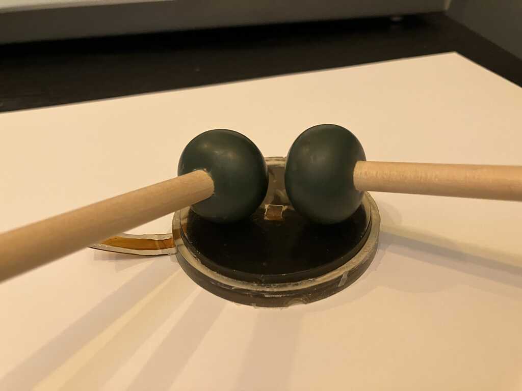
Check size with 2 type of mallet sticks. This is a perfect size. Great guesswork :-)
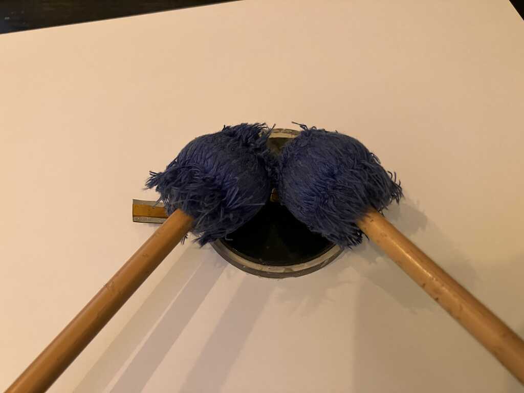
As you can see the top and bottom parts were not properly attached.
And there’s PU inbetween the velostat and flexPCB layer. #fail
failures
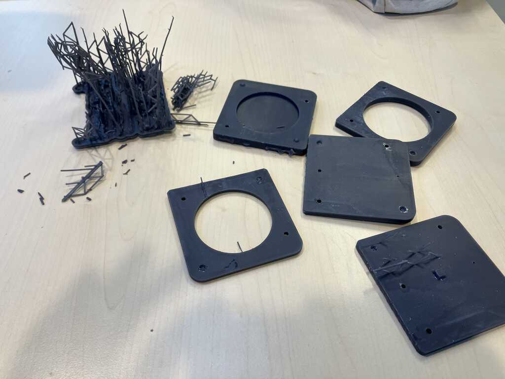
In the cleaning stage, the IPA could clean enough on the underside because the support prevented IPA to properly flow through. So one of the sides (plate side during printing) is a bit strange-looking.
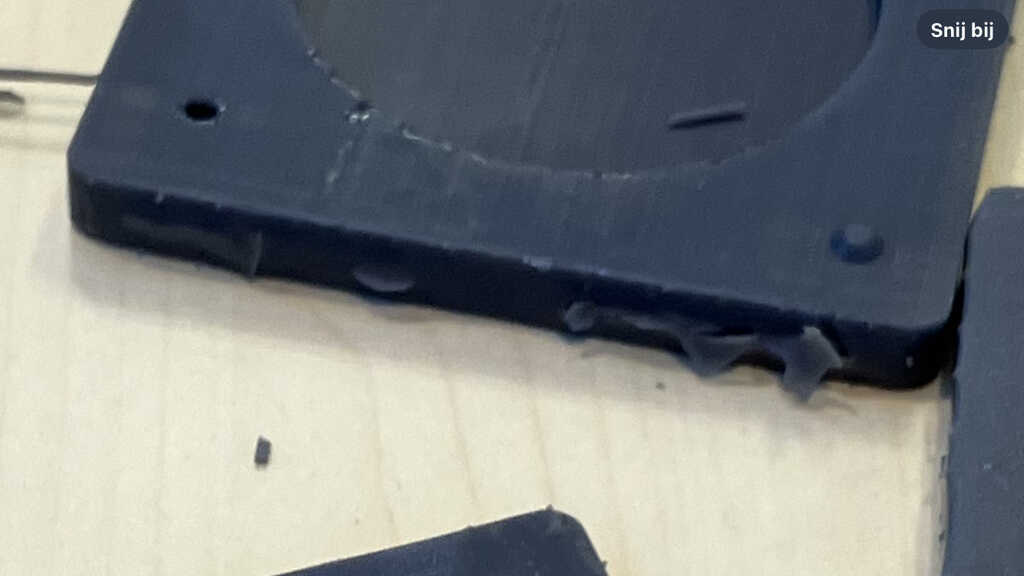
I also designed the syringe hole to small. It should be 4mm. Airvent hole could be a bit wider as well: 2mm. I used a drill to make these holes larger.
I had PU residu between the velostat and flexPCB layer, preventing it to work properly. So need to find a way to prevent this.
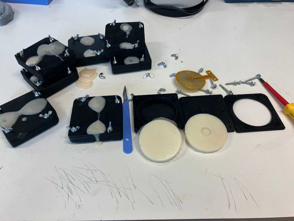
more casts
I created some more casts of the top part. This time shore 90 and shore 30 PU to check which shore value would be best to use. Shore 90 on the left, 30 on the right. They came out very nice. Shore 90 has a bit of flashing but that was easy to cut away. I didn’t make enough shore 90 PU , so as you can see there are some holes. No worries, it’s just a test to see what shore I want for the top part.
I also casted a few more bottom parts. I already made a shore 30 one, so I also made a shore 60 and shore 90. Again, to check what shore I want for the bottom part. I intentionally added mold release on the top parts so they will not stick to the bottom part. That way I can mix & match and pick a winner.
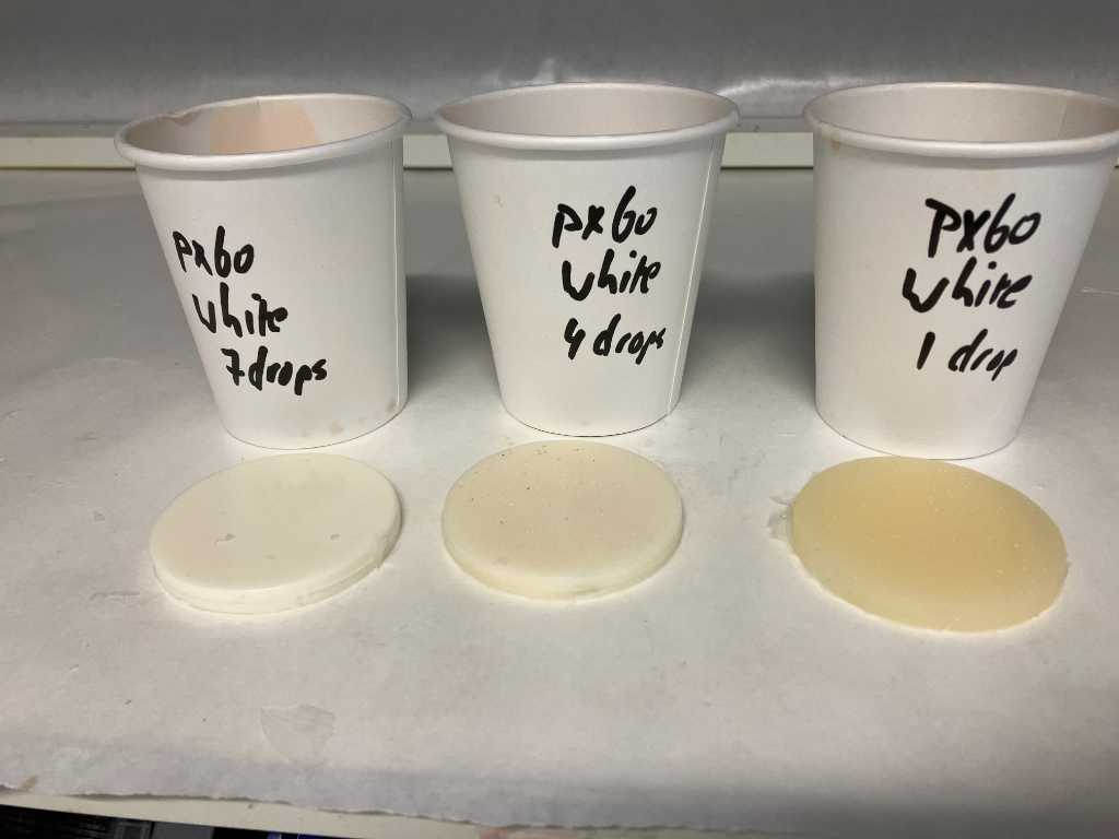
Also in the image below are 2 top parts casted with added white pigment. One with just 10 drop, the other with a lot more. There will be LEDs below the top part and the light should light up the hole top layer instead of shining right through. So hence the pigment as a test.
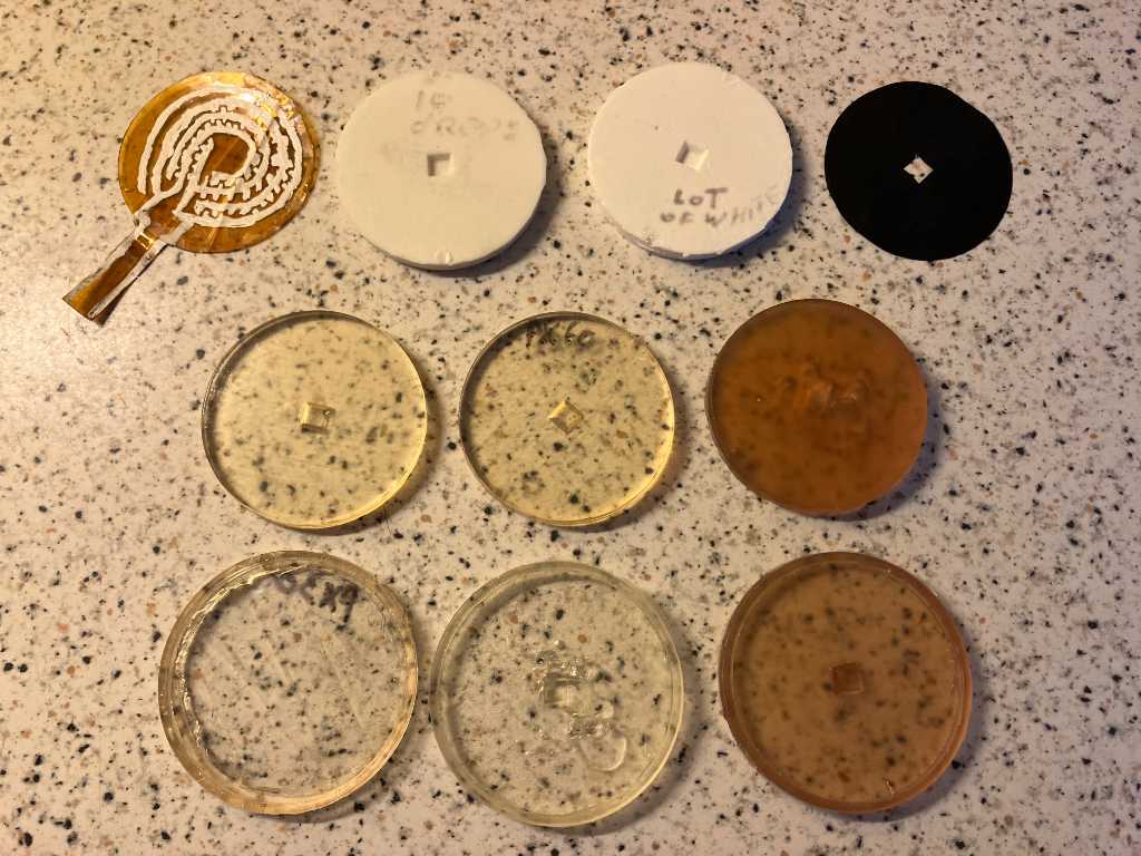
The result:
- Bottom left & bottom middle = PX30 (shore 30 PU)
- Bottom middle & middle middle = PX60 (shore 60 PU)
- Bottom right & middle right = PX90 (shore 90 PU)
- Leftmost white cast = PX60 with 10 drops of white pigment
- Rightmost white cast = PX60 with a lot more white pigment
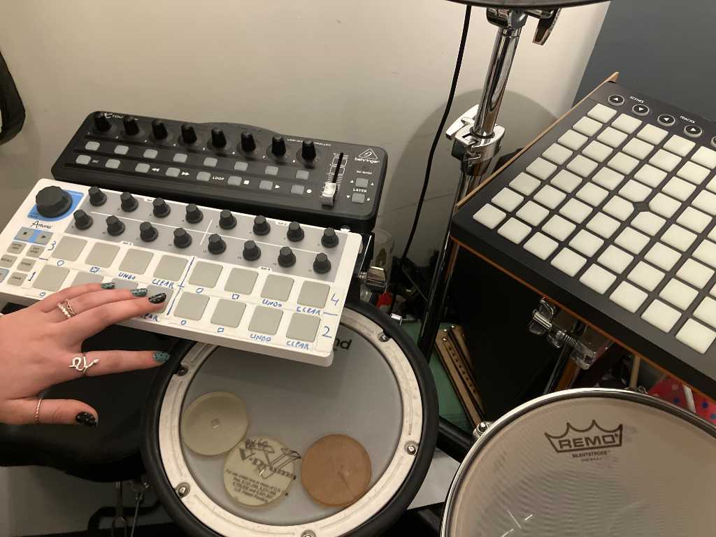
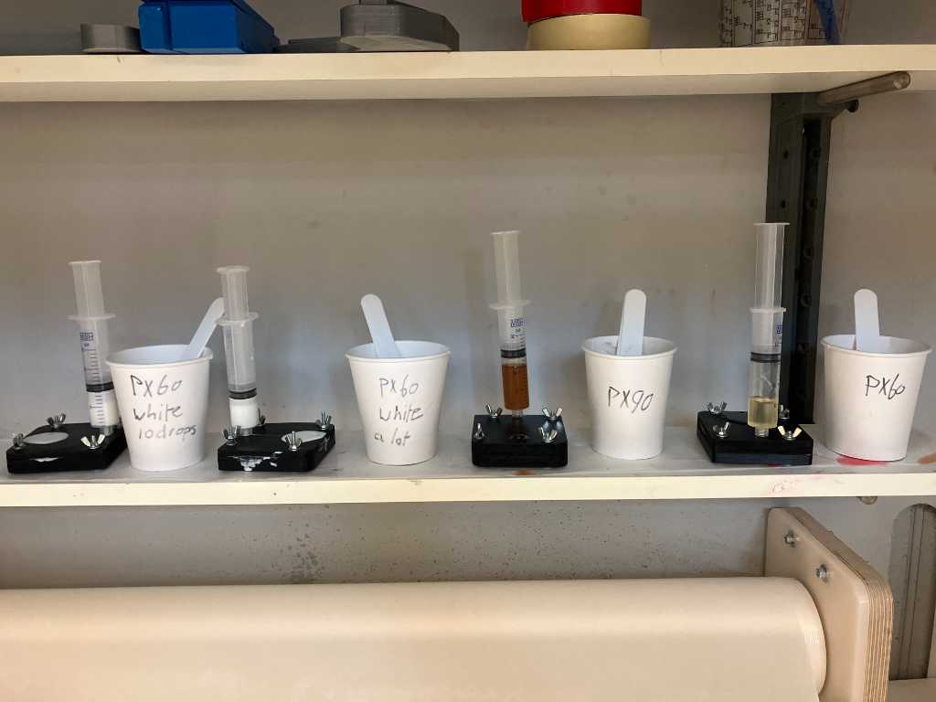
Together with my daughter who plays the marimba we tested which pad would be the best trade-off between perfect bounce and not too loud. On the photo you see some other Midi controllers that I have. We checked their bounciness as well. The px60 (both top part well as bottom part) came out as winner. So I’ll continue making them from px60.
more white
Next part is to see how much white pigment is required to create a pad that is translucent enough to light up nicely when the RGB LED underneath is on. But Not too much translucent because I want the light to be spread throughout the pad as much as possible.
So I casted another 3 pads: 1 drop, 4 drops and 7 drops of white pigment. Next will be to test it with an actual RGB LED.
Flexible PCB
I exported the outline of the flexPCB from Fusion360. Next I imported it into kiCAD because I wanted the WS2812B footprint.
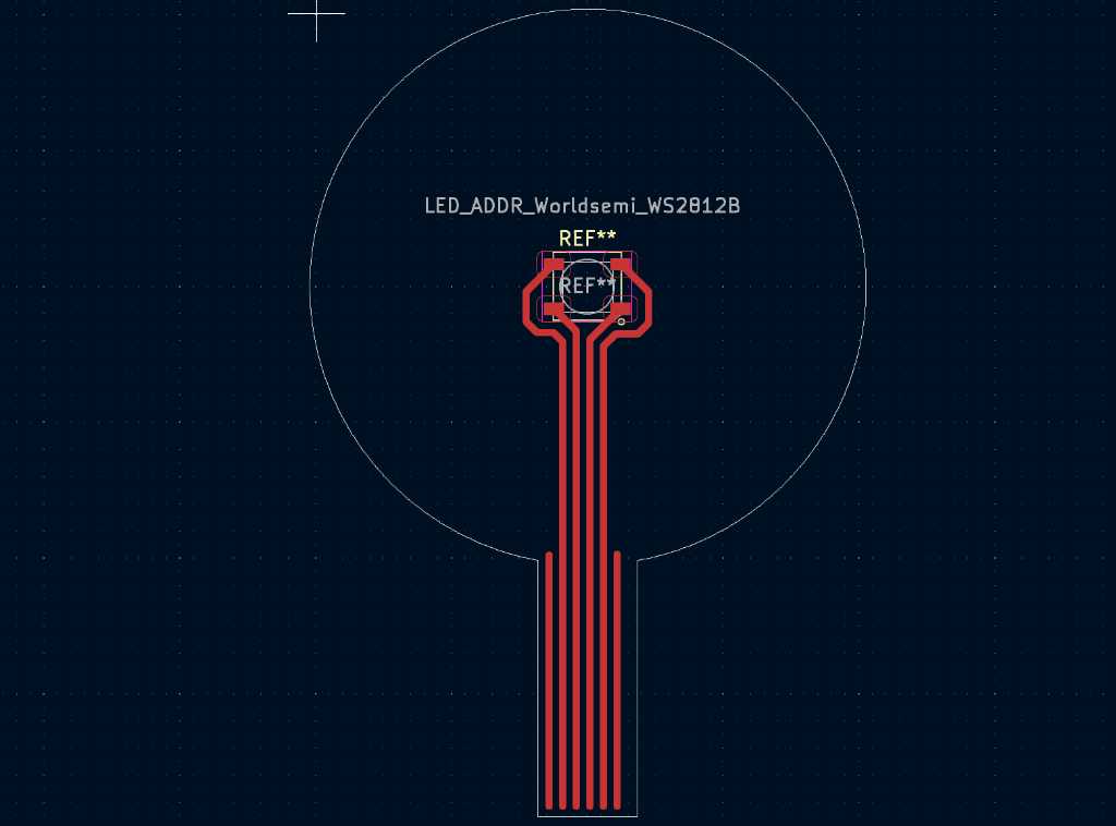
After that I exported this as SVG and imported into Illustrator. This let me design the round traces:
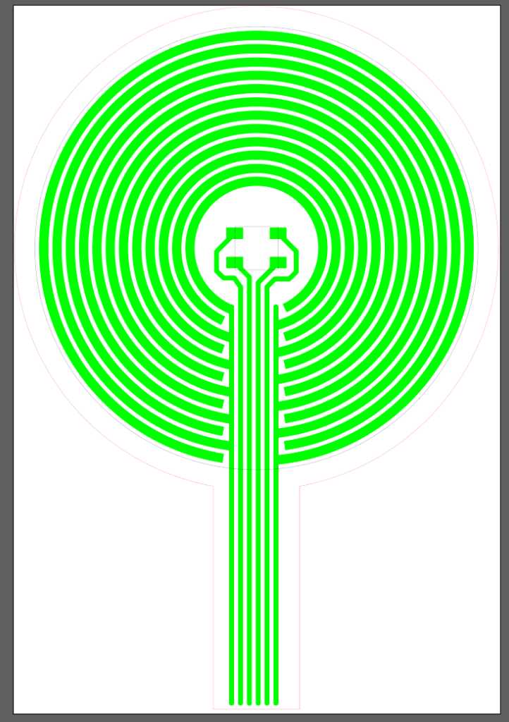
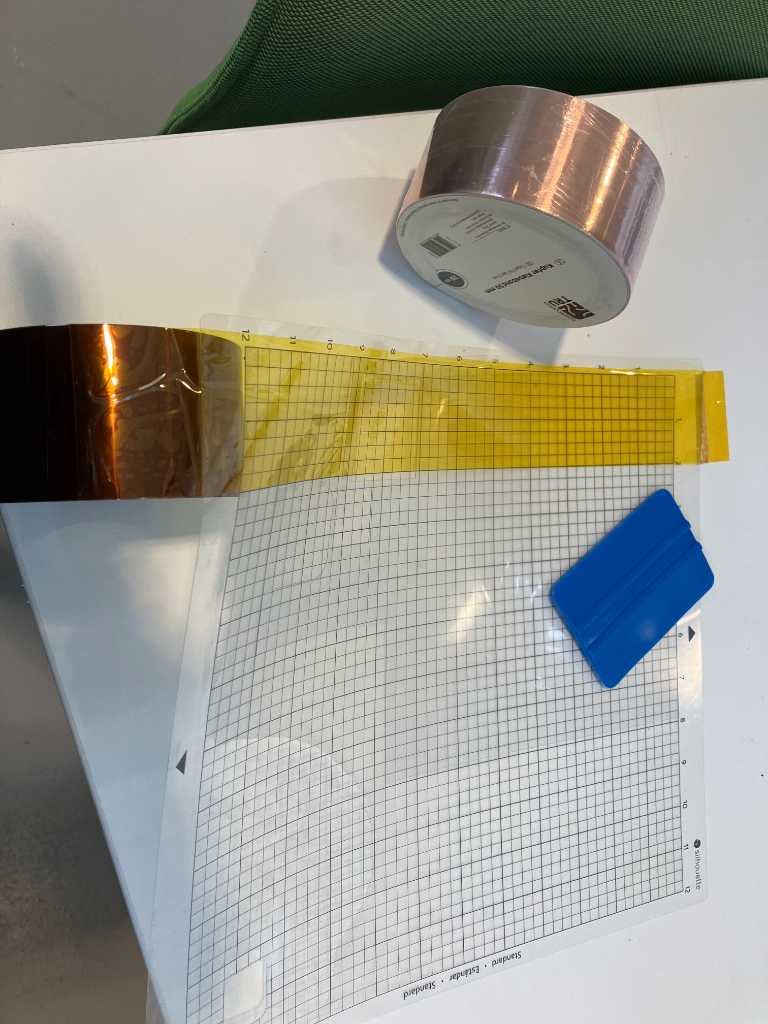
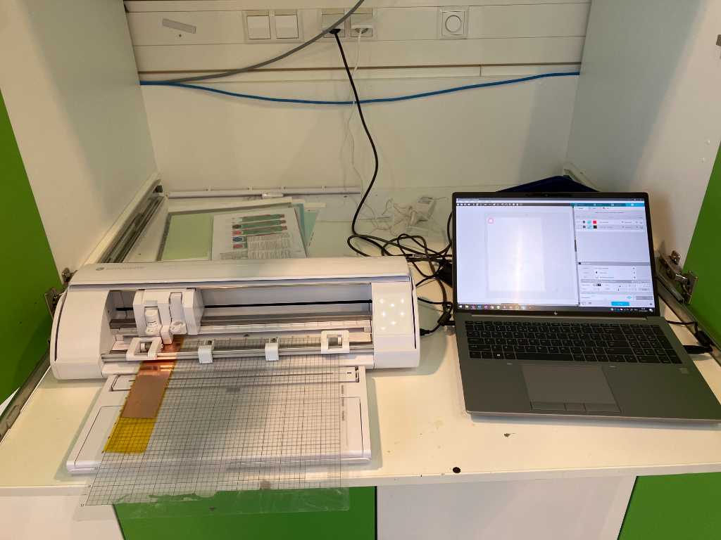
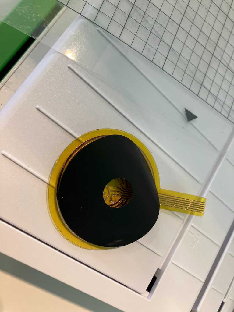
So let’s go and cut this using our Cameo 5. The things to cut are: Kapton, Coppertape, foil and Velostat.
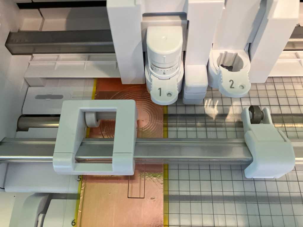
First I added a layer of 0.2mm transparent foil onto the sticky matte. Next 55mm wide kapton tape. Next 50mm wide copper tape.
doing a test cut in Silhouette studio:
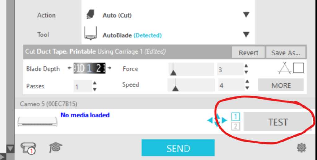
settings to cut only through copper layer:
- Blade: autoblade
- blade depth: 1
- passes: 1
- force: 3
- speed: 4
Settings to cut through sheet and kapton:
- Blade: autoblade
- blade depth: 7
- passes: 1
- force: 33
- speed: 5
Looking great! But not fully on the copper tape. Alignment is hard apparenty. #fail
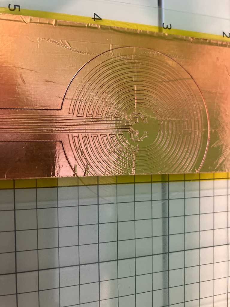
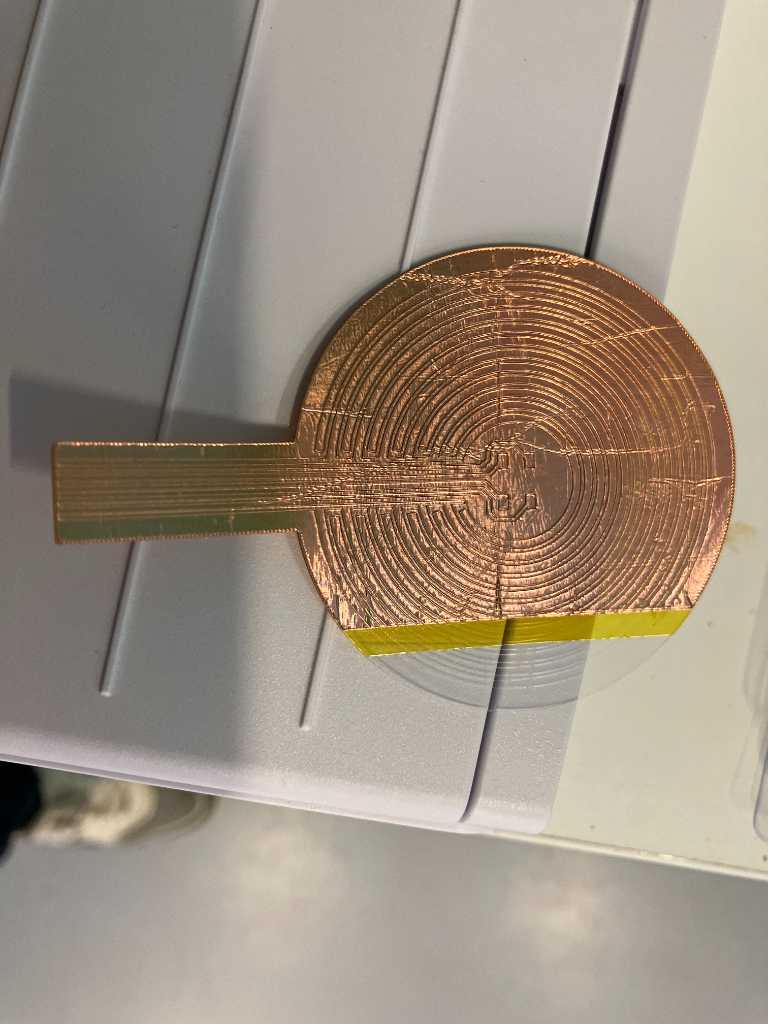
Weeding nightmare….
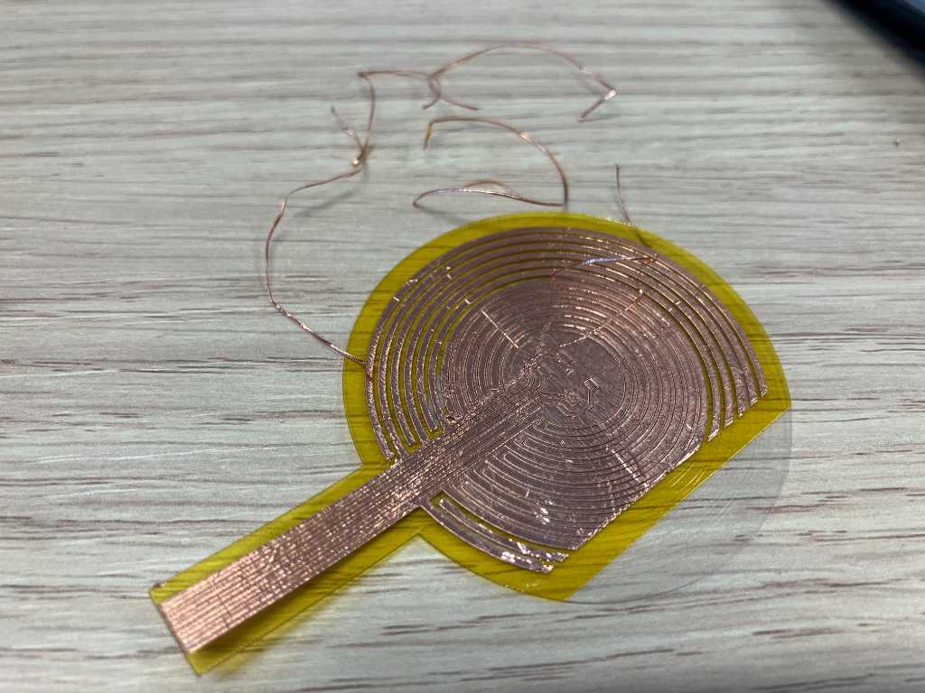
This was a lot of work. I think I broke one of the traces to the WS2812B LED. But at least I have something to try. And the pressure sensor works really good! This is just a quick test with a single piece of velostat on top of the traces.
Pressure sensor resistivity
I measured my Velostat pressure sensor using a multimeter. The resistance readings that I get are Mega Ohms order of magnitude. So although the idea works, the “sensitivity” is by far not good enough. It should be more like KiloOhms or less.
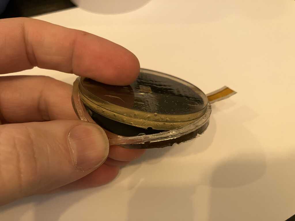
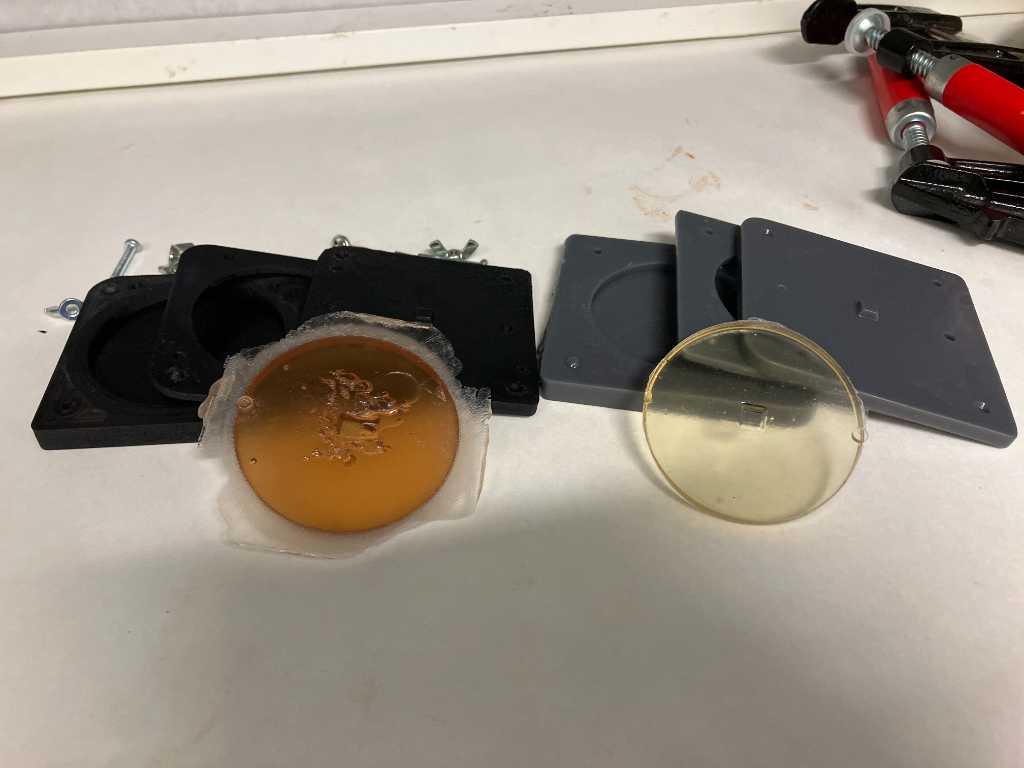
I have an Arturia Beatstep midi controller lying around. It has pressure sensitive buttons, so I opened it up to see what I could learn from it.
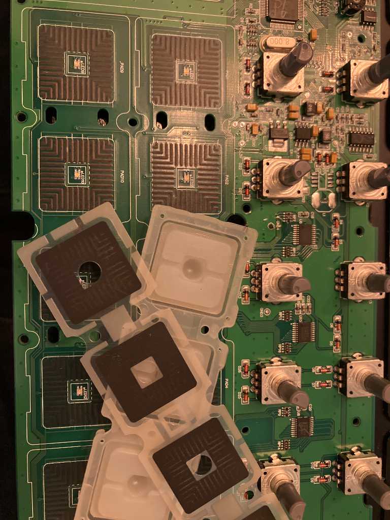
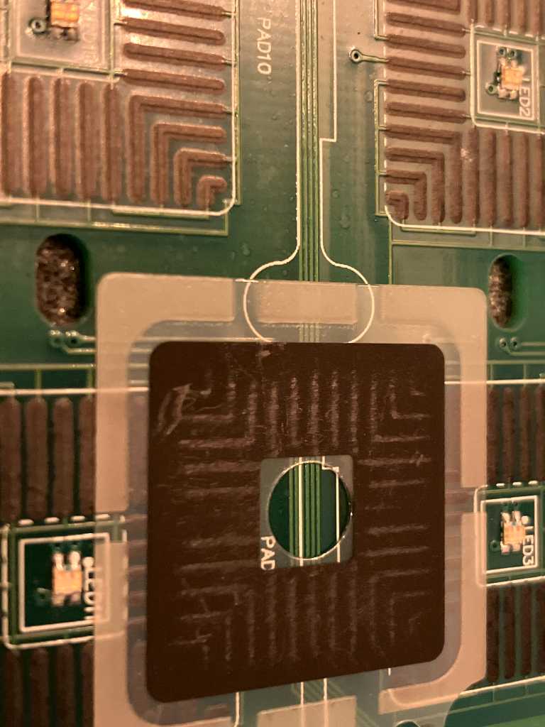
Without knowing it before, I found that the idea is actually very similar to what I’m doing! A PCB with traces (spacing quite close to what I have, maybe a bit more narrower), a thin piece of plastic sheet with some kind of piezoresistant material on top (I guess carbon) and a molded piece of rubber/silicon/TPU (by the feel of it with just about the same Shore as my PX60 pads, maybe a bit more flexible).
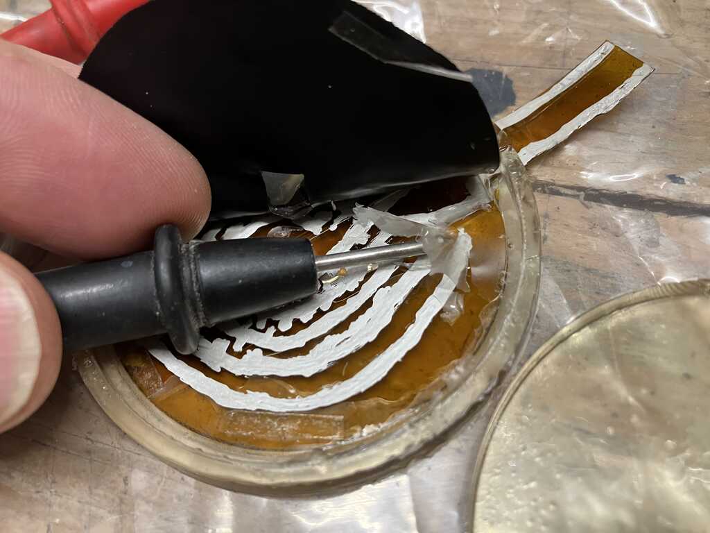
I wanted to test if their piezoresistant material is similar to Velostat, so I did an A/B test using my flexPCB:
As you can see in these videos there’s a huge difference. Velostat is Mega Ohms order of magnitude (when pressed really really hard I can get it just below 1MOhm) and theirs easy to get below 1kOhm.
So I have to conclude that the way I’m using Velostat here will not be sufficient. Either I have to redesign my flexPCB (traces even closer? But I can’t weed that anymore. Or use sandwich method with copper on top and bottom and velostat in between? But that’s a much more difficult design that what I have now). Or I have to see if I can get better piezoresistant material.
I googled myself into the suburbs of the internet and found pcb manufacturers like RayPCB and eurocircuits who explains on their sites that the carbon conductive layer is called “Carbon Ink”, particularly useful for keyboard/keypads, etc. But nowadays also used instead of silver or goldplating, to protect copper from corroding while still maintaining conductive surface area. It is applied to the PCB using screen-printing. It also adheres very good on flexible materials such as polyamide films. Here’s a technical datasheet of such material provided by Eurocircuits.
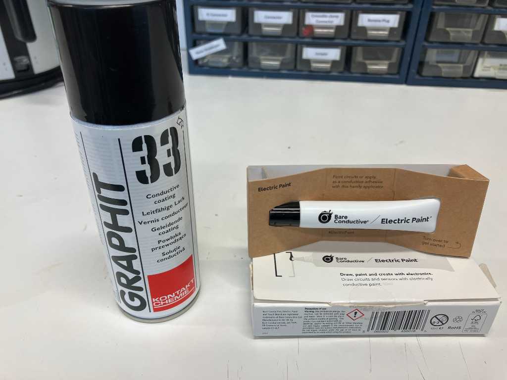
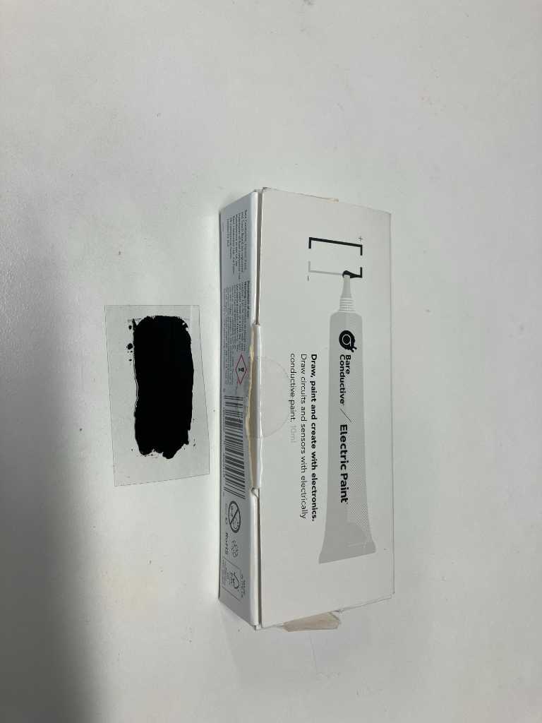
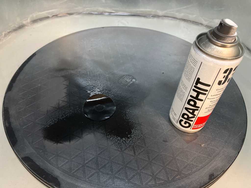
In our fablab we have 2 different types of graphite: A spray and an ink. Lets try to put them onto a piece of sheet and see if resistance is better measurable than velostat.
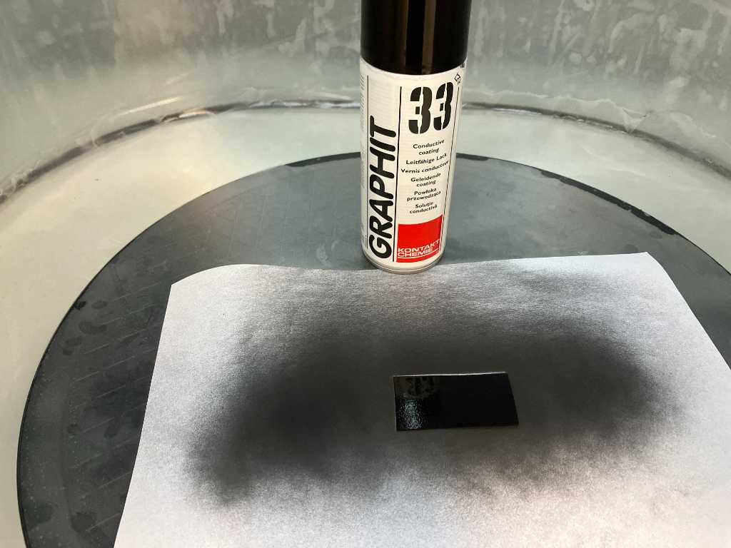
As you can see this looks very promising! This is with the Graphit 33 spray. Works great and a good candidate to make better pressure sensors. Although the copper traces will have to be sprayed too so they don’t corrode. But I have to leave gaps otherwise the traces will conduct even without sheet on top…
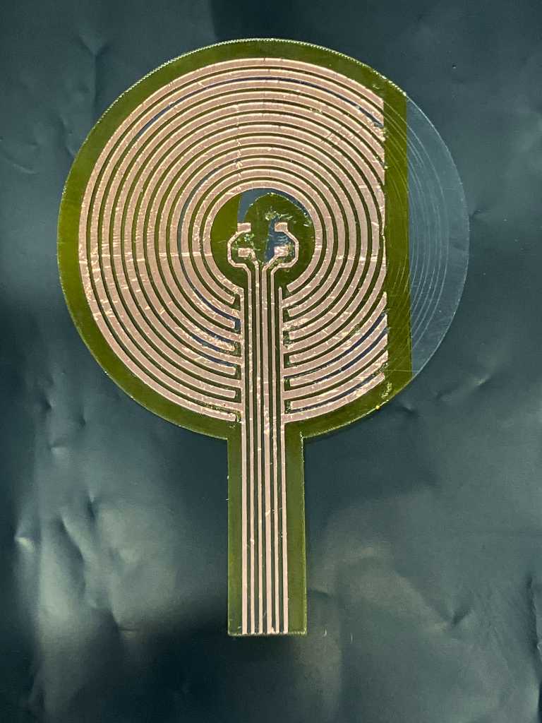
a fully working test unit
With a bit of alignment on the Cameo and again lots of weeding, this is the result.
Next up is creating a piece of velostat that will fit and applying Graphit 33 to it for more conductivity.
I’ll make the velostat on the Cameo vinylcutter using the following settings:
- Blade depth 2
- cut force 33
- passes 2 (I think 1 will work too)
- speed 3
After a while the graphite ink crumbled of the velostat very easy. Apparently these two materials don’t match. So I decided to use a piece of transparent plastic sheet, cut that using the vinylcutter and spray this graphite ink on. That holds much better.
Then soldering the WS2812, the resistor and the capacitor. I also have to cover the traces using a small piece of kapton.
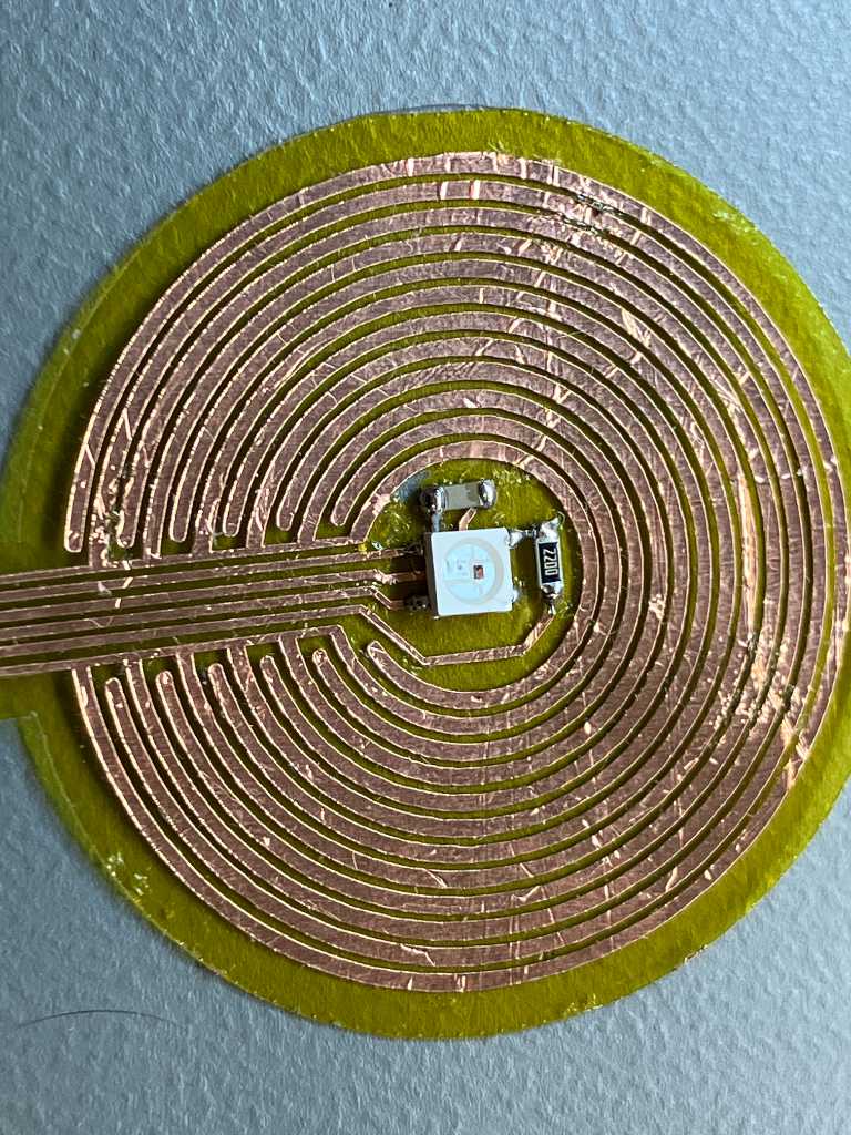
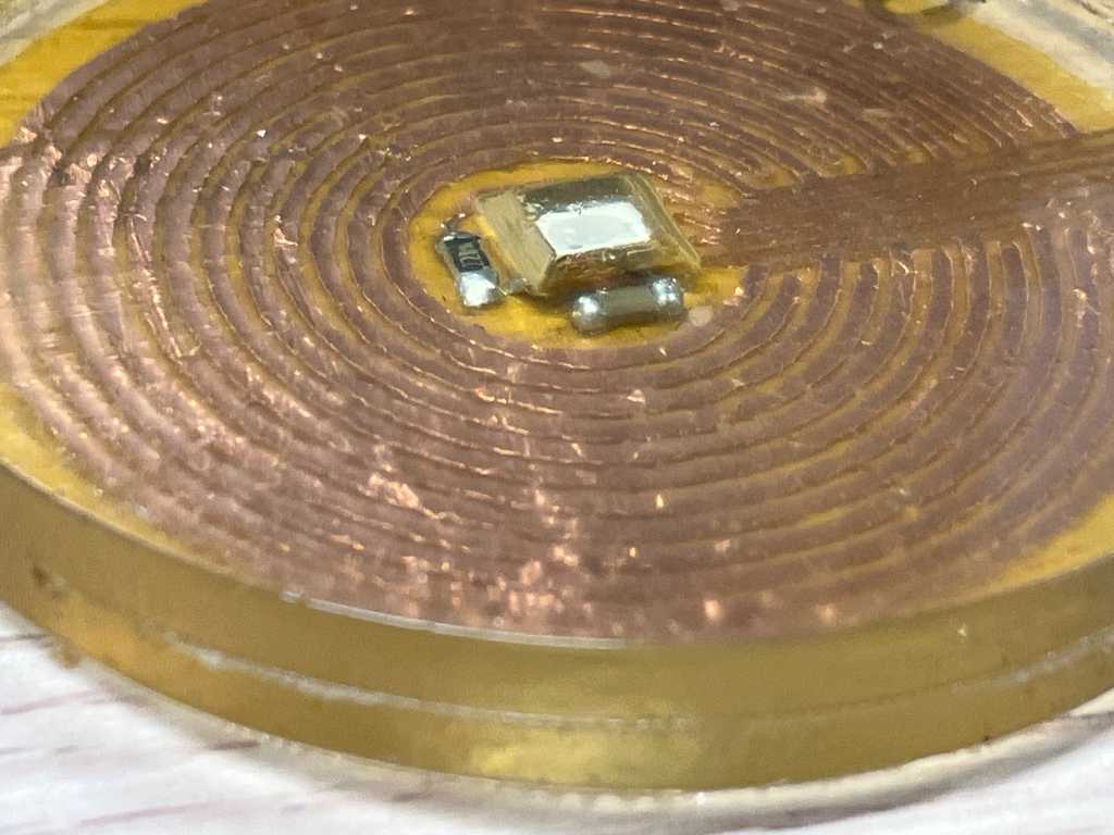
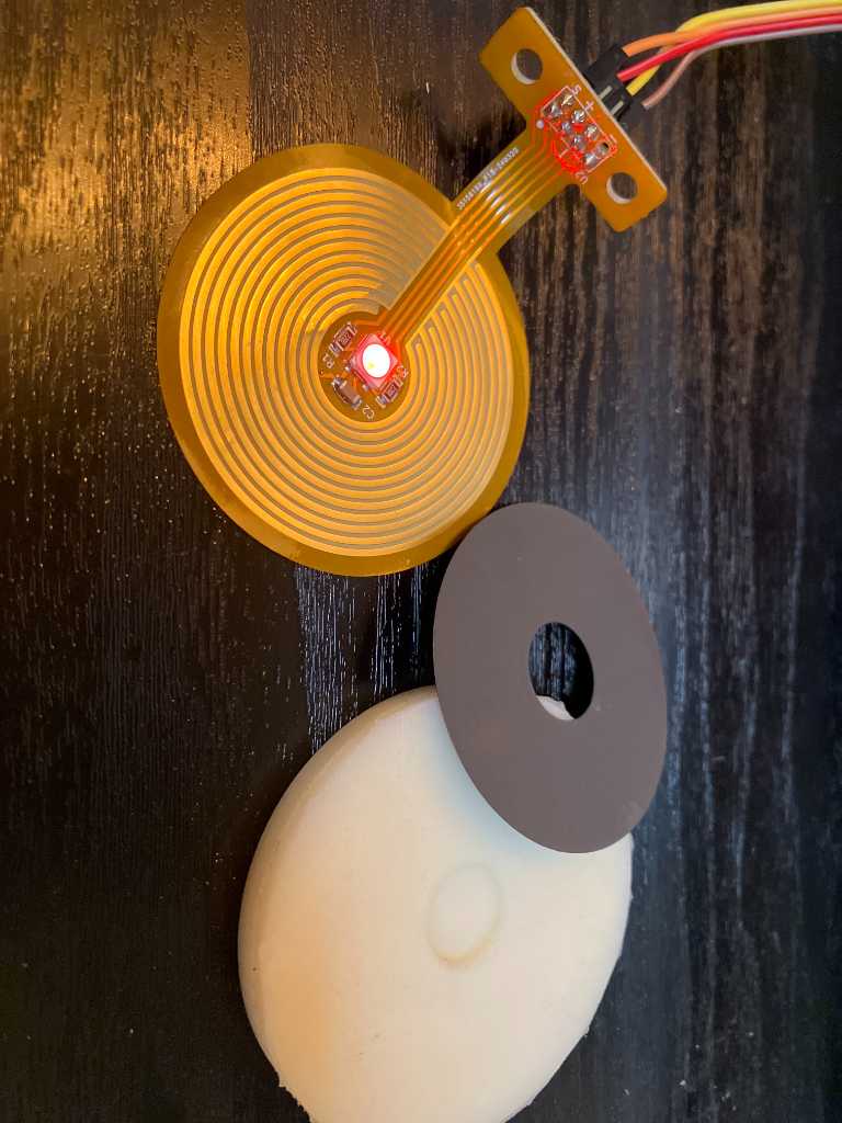
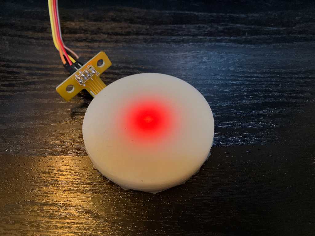
Testing the components using the SAMD11C14 board and test programs that I made in embedded programming week: the WS2812B worked
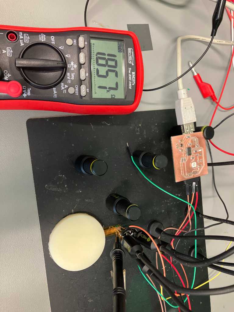
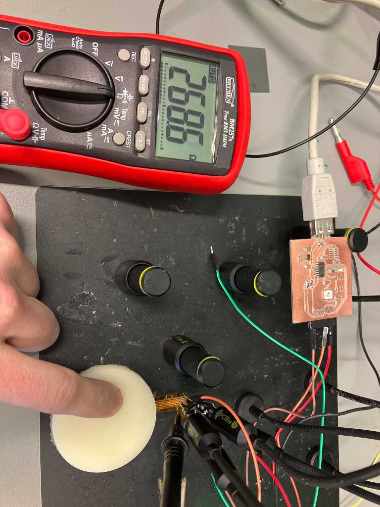
Time to test the pressure sensor. Here are all the components:
The resistance of the sensor without and with pressure is between 2 kOhm and 200 Ohm.
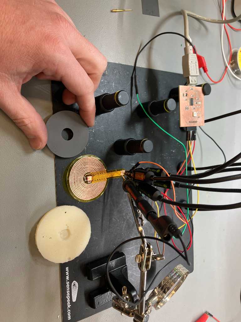
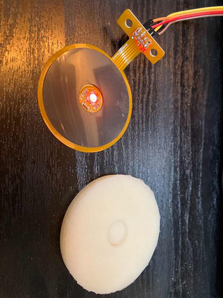
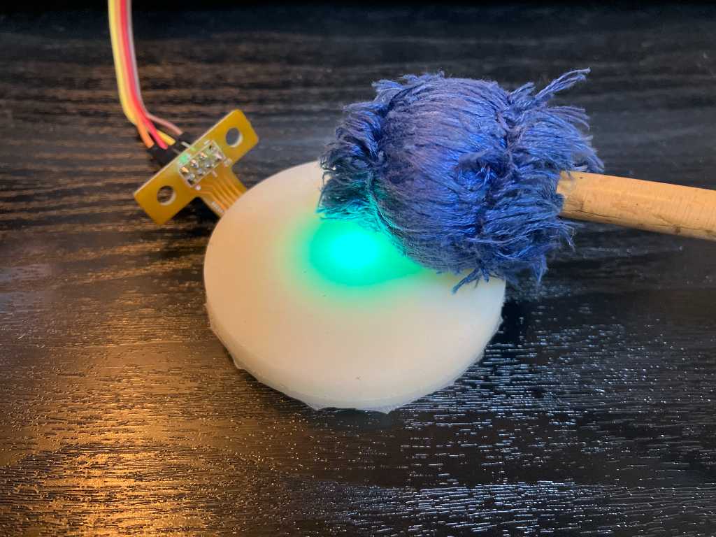
And now putting it all together, again using the program I made in embedded programming week:
Alright! So this all works very nice!
Next is putting this into the mold and cast the bottom part.
I found out that in the mold of the top sensor part I only took into account that I have a LED on top of the flex-PCB. But I also have a resistor and a capacitor. So it doesn’t fit now. I should change the top tool… For this test unit I used a sharp knife to cut a bigger hole in the top tool.
To make sure there will be no PU between the sheets and my flexPCB, I glued the rim of the flexPCB to the top sensor part using superglue.
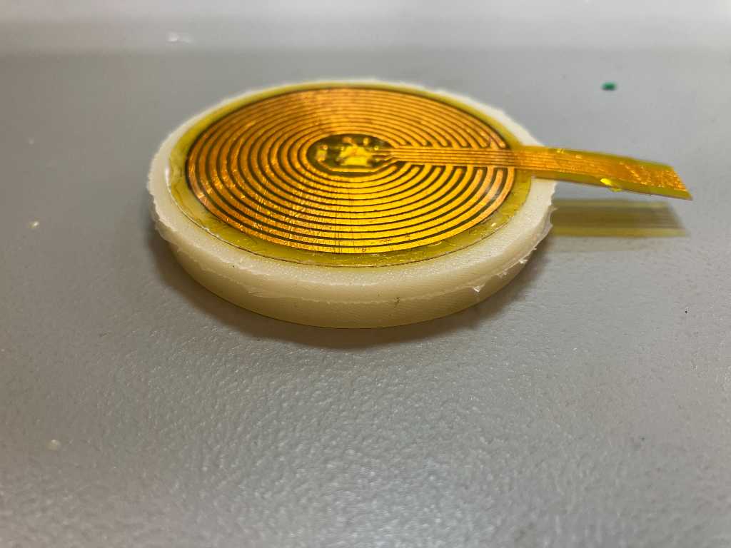
Pinout from top to bottom as seen in this image:
- Sensor out
- Ws2812B data in
- Ws2812B data out
- Ground
- 3.3V
- Ground
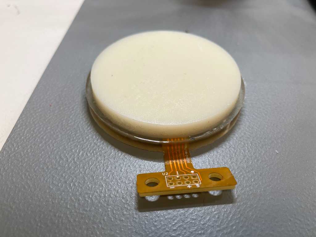
Thing are ready for the final casting. And here’s the result:
Production time
The steps to produce the pressure sensors are:
- 3D print molds for the top and bottom part of the sensor
- Cast the top sensor part
- Cut circles out of PET sheets and spray them with graphite spray
- Solder the flexPCBs
- Glue PET circle and flexPCB on the top sensor part
- Put this combination into the bottom sensor part mold
- Cast the bottom sensor part
3D print molds
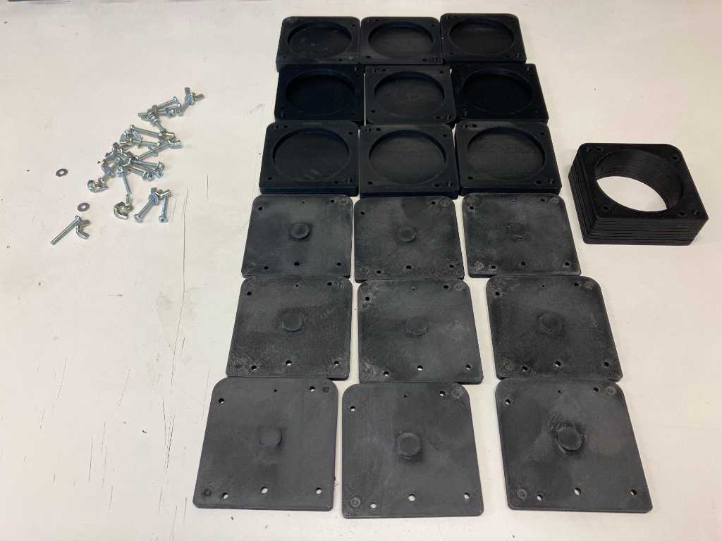
All molds are printed on Bambulabs X1C using black bambu PLA basic with 0.12mm High Quality @ BBL X1C preset on Cool Plate/PLA plate.
0.12mm layer height, 2 walls, 5 top and 5 bottom layers of 0.6mm, 15% gyroid infill. 50 mm/s initial layer, 105 mm/s initial layer infill, 60 mm/s outer wall, 150 mm/s inner wall. infills 180 mm/s, top surace 150 mm/s. No supports required.
The molds are held together with 25mm M3 bolts, with a washer and a wingnut.
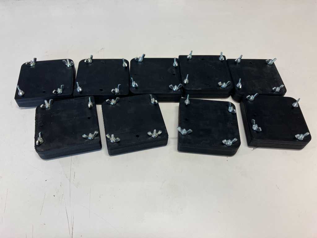
Cast top sensor part
Casting is done with Xencast PX60. It has a pot time of 10 minutes. In this time I was able to do 90ml PU (45ml Part A and 45ml part B), 4 drops of white pigment. With this I can cast 3 top units. 4 top units can be casted with 65ml part A, 65ml part B and 6 drops of white pigment.
The bottom part requires a little over 10ml of resin (5ml part A, 5ml part B) per part.
I used a 20ml syringe to get the PX60 into the mold.
There a bit of flashing and so I need to peel that off. Sounds like a job to do outside in the sun.

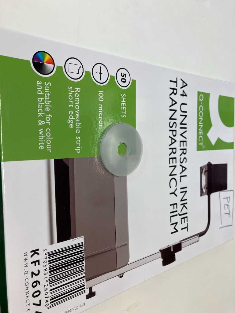
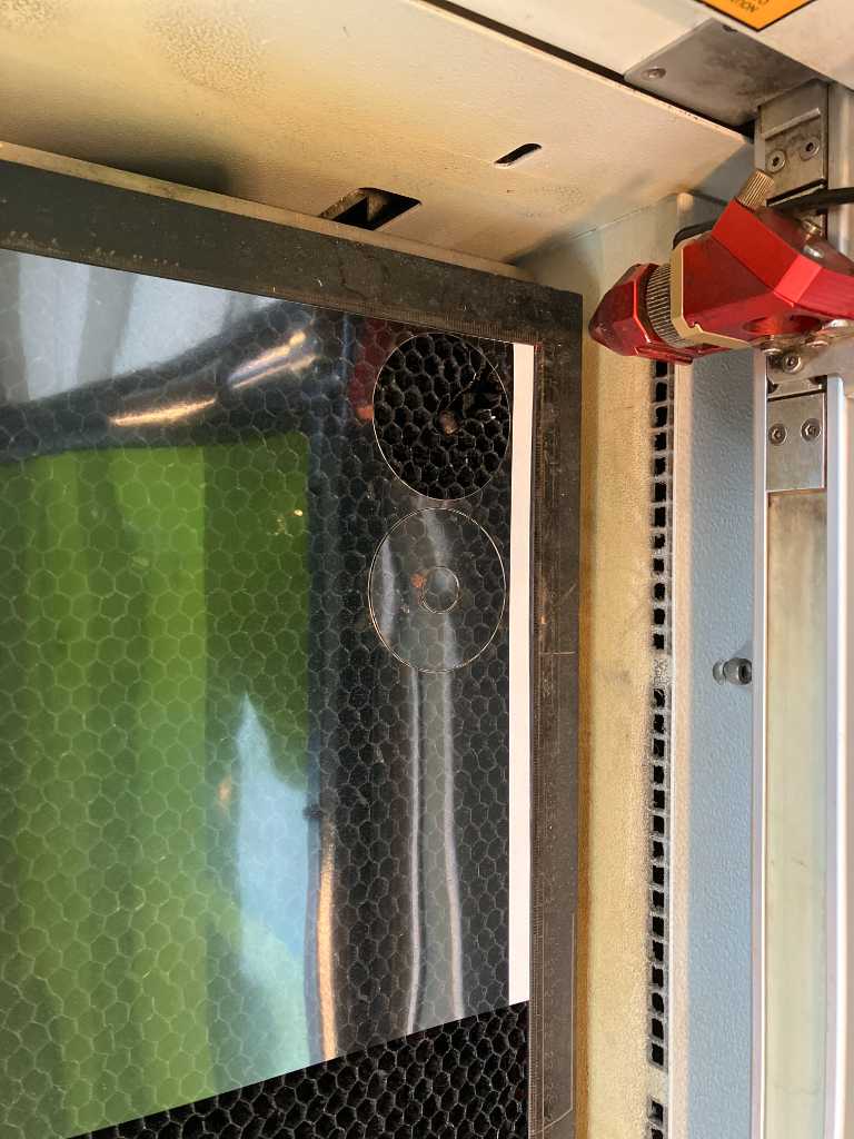
Cutting PET sheets
I’m using universal inkjet transparency film, which are generally used for overhead projectors. I selected this specific type because it is made out of PET (so it can be lasercut), has a well-defined thickness (100 um) and because it’s made for inkjet printers, I think the graphite spray will stick better.
Lasercutting with trotec speedy 300, CO2, with speed 4% and power 30%
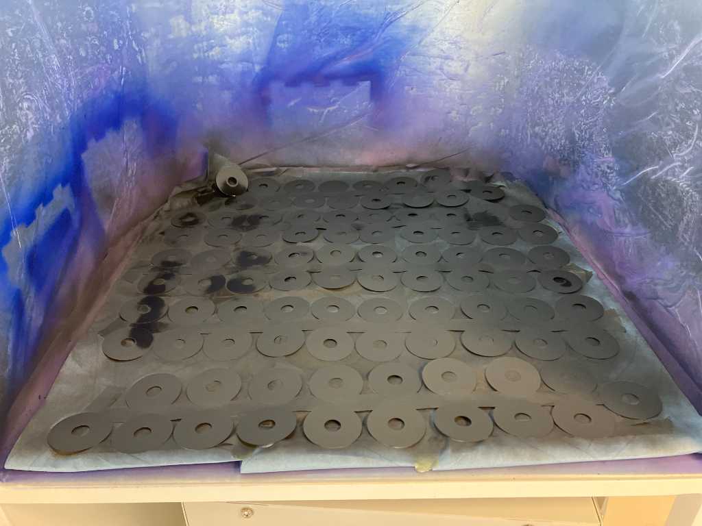
painting these with a spray can (carbon ink) is actually quite hard :D
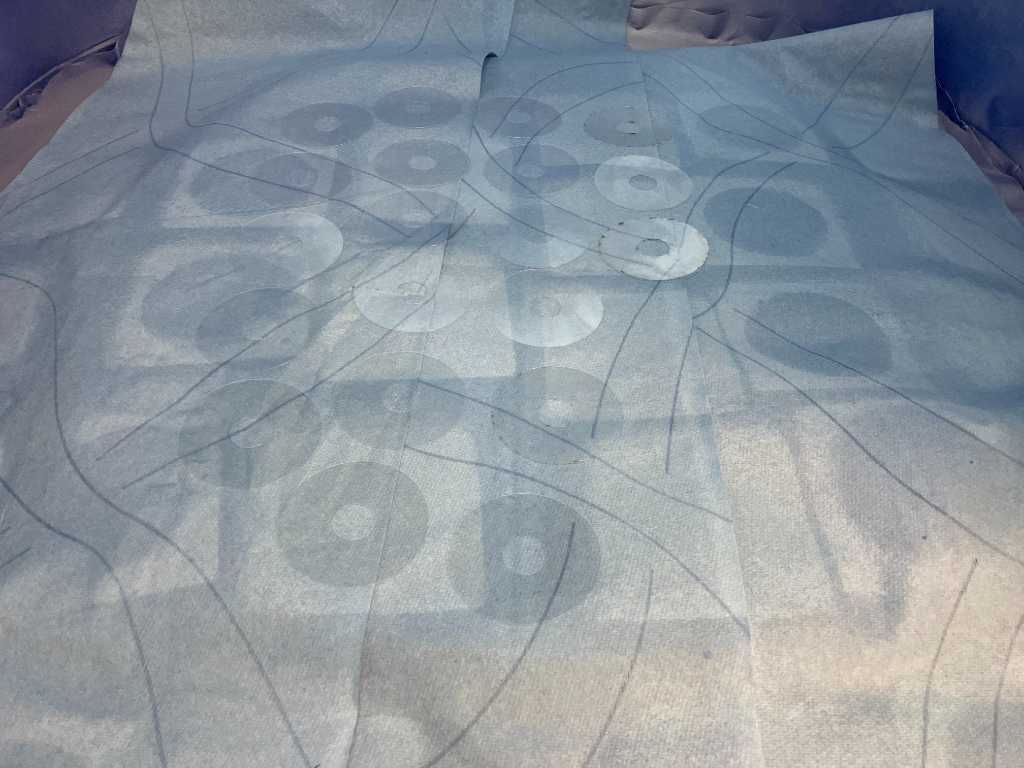
But a bit of tape does wonders…
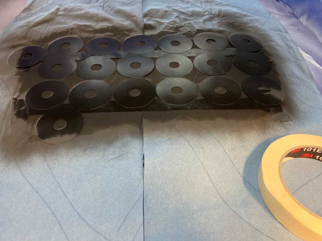
More!
soldering flexPCB
I’ve soldered the 2 resistors, 1 capacitor and the WS2812B LED to the flexPCB using solderpaste and a heatgun. The connector on these images is not the final one. This one is just easier test with. The final connector will snap directly onto bandcables.
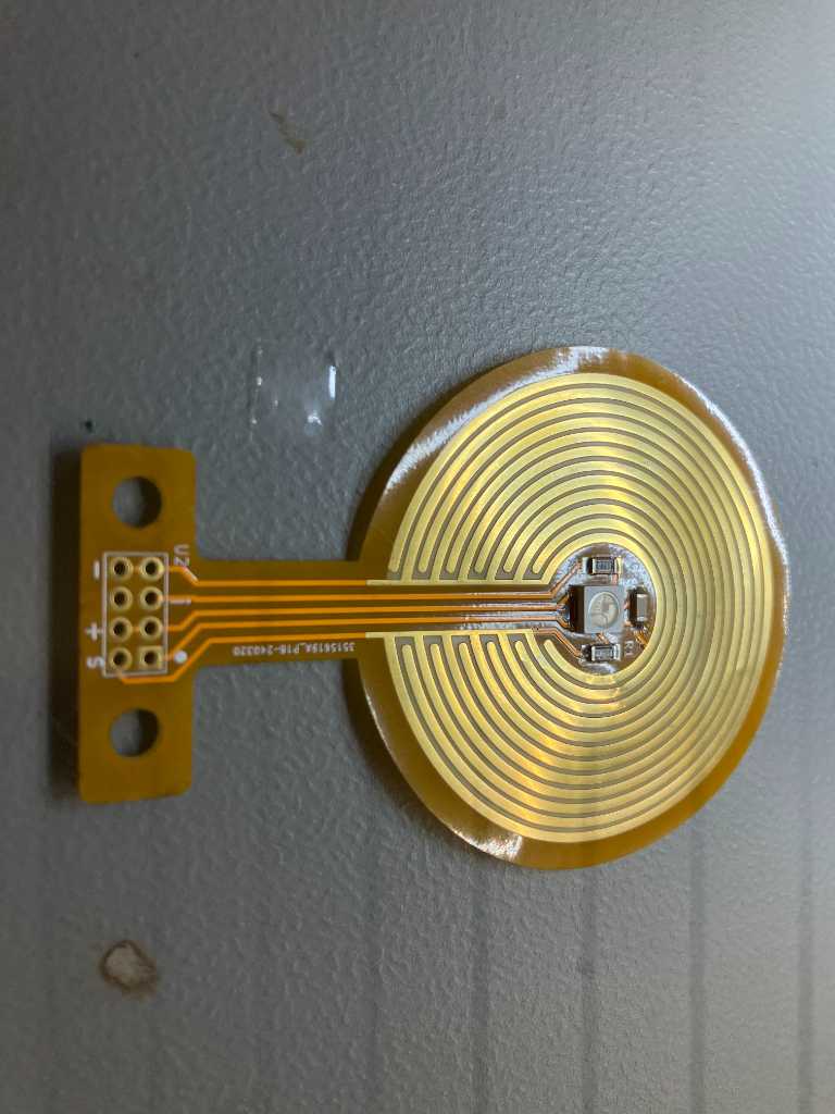
All parts are ready for the test and final glueing/molding:
I tried various adhesives to get the PET circle and the flexPCB to stick to the PU of the top sensor part. Especially the flexPCB is hard to glue. But it needs to because otherwise PU will get underneath it when casting the bottom sensor part…
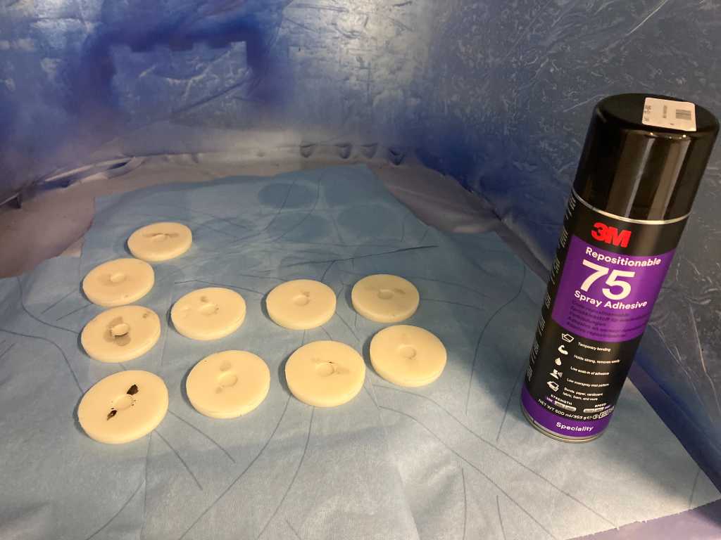
Eventually UHU glue stic (and keeping the parts under pressure for an hour) worked. The PET circles sticked to it because of the spray adhesive. The UHU stic I used to put glue onto the outer sides of the flexPCB.
molding
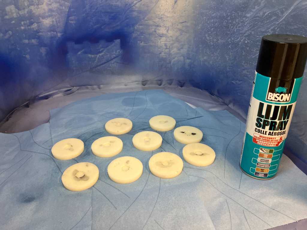
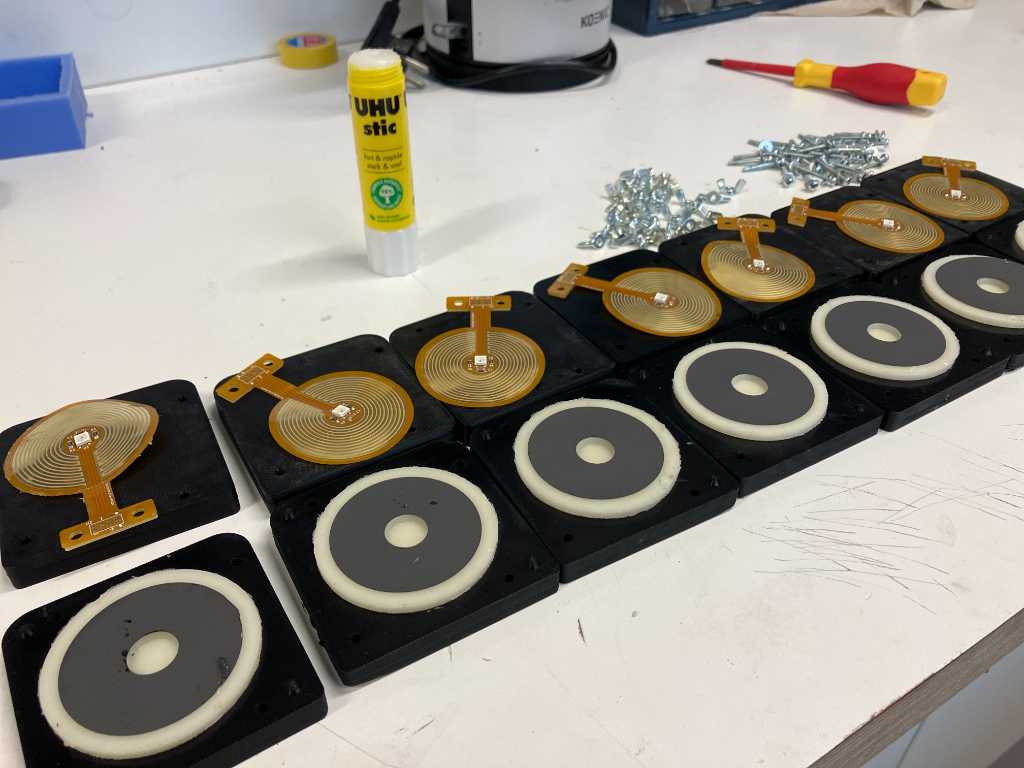
Finally 10 pieces in their bottom mold:
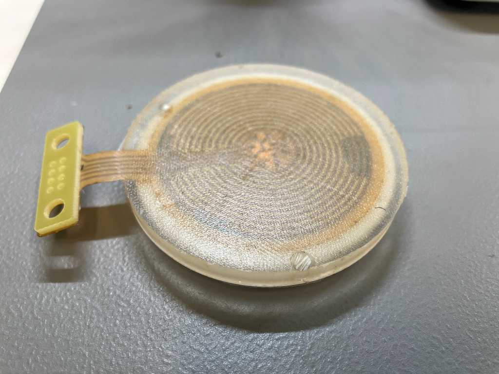
The result is not what I hoped for. The two PU parts don’t quite stick together. Also on at least 2 out of 10 PU got in between the graphite sheet and the PCB, rendering it useless.
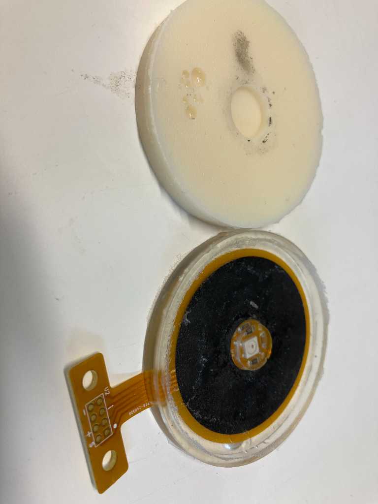
It should not have overmolded the LED…
This one was good:
They do look nice though :-)
glueing top and bottom
Simson cement svs-Vulc nafta Pattex superglue gel ethylcyanoacrylaat Bison bisonkit contact adhesive ethyl acetate Pattex power fix polymer
The one that worked is the Pattex Power Fix Polymer glue. The others were easy to take apart again.
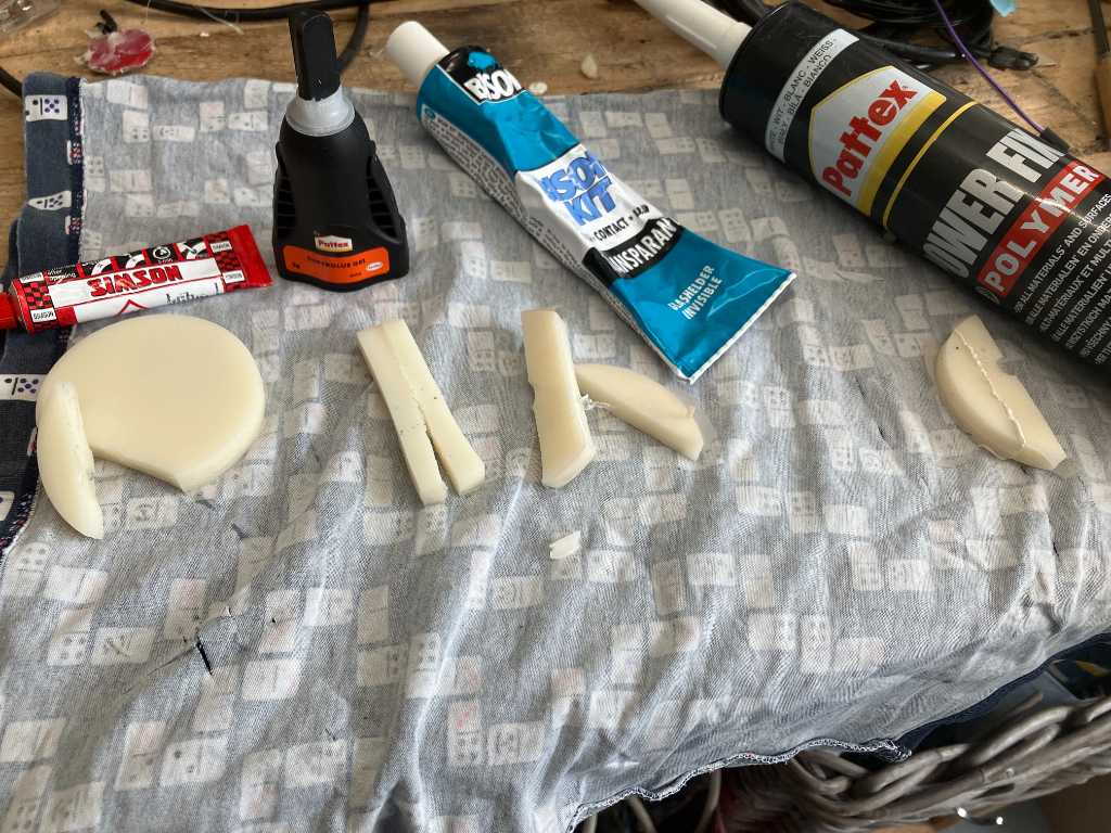
So I’m going to use that glue to attach the top to the bottom with the PET sheet and the flex PCB in between.
First cut a small opening in the bottom part so the flex PCB can come out.

Next add glue to both the top and the bottom part.
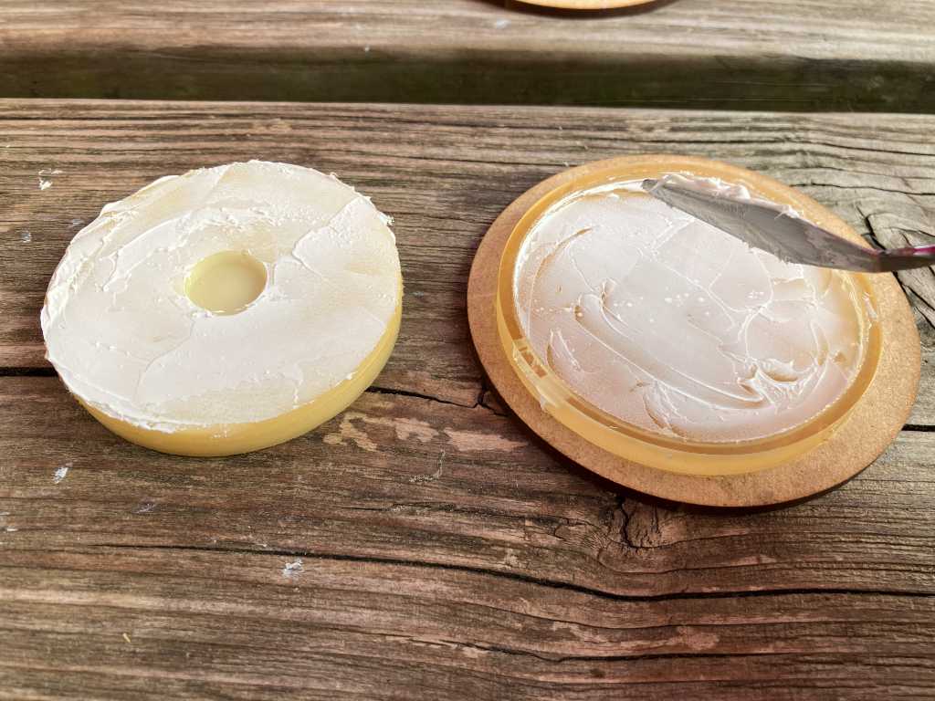
Add the PET sheet (carbon coated side on top!) to the top part and the flex PCB to the bottom part.
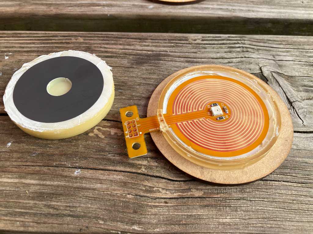
1 done. 75 to go.
