computer-aided design
Topic(s) of this week
- computer-aided design (video, review)
- Evaluate and select 2D and 3D software
- Demonstrate and describe processes used in modelling with 2D and 3D software
Assignment
Individual assignment
- Model (raster, vector, 2D, 3D, render, animate, simulate, …) a possible final project, compress your images and videos, and post it on your class page
What I think I already know
I have working knowledge on Fusion 360.
I have a good knowledge of Adobe Illustrator and Photoshop.
I know how to program, so scripting in openSCAD should not be a big issue. Programming for 3D design output will though.
What I want to learn
Blender. OpenSCAD. Cuttle.
SSTM planning
Supply
| Day | Supply | Tasks |
|---|---|---|
| Thursday | 08:00-09:30 (train) | |
| 10:00-18:00 @ WAAG | ||
| Friday | 9:00-13:00 (fablab) | no FA time |
| 20:00 - ? | ||
| Saturday | ||
| Sunday | 14:00 - 17:00 | |
| Monday | 16:00 - 17:00 (fablab) | |
| 20:00 - ? | ||
| Tuesday | 9:00 - 11:00 (fablab) | |
| 15:00 - 17:00 | ||
| Wednesday | 9:00-12:00 (fablab) | |
| 12:00-13:00 | Local review | |
| 13:00-14:00 | Regional review | |
| 15:00-18:00 | Neil time |
tasks
Have you answered these questions?
- Modelled experimental objects/part of a possible project in 2D and 3D software
- Shown how you did it with words/images/screenshots
- Included your original design files
Individual assignment
2D design
Cuttle
Interesting software in browser cuttle.xyz. this is a design tool for digital cutting machines. I had a look at the website. There are lots of beautiful examples and inspiring projects. The website is “free for casual use”, which means a limit to 5 projects, 10 downloads per month and personal use only. Especially the 10 downloads per months sounds very very limiting to me, so I’m not going to try. Only be inspired.
Illustrator
Making a linked clone in illustrator can be done using symbols Unfortunately you can’t use pathfinder with symbols. By the way, you can’t do this in inkscape either. It looks like this works if you look at Neils’ video here at 0:52 but he just creates white shapes. He didn’t do a boolean operation first and then change the clone.
When tracing images in Illustrator you might get large amounts of path points (anchors). You can simplify this using object - path - simplify:
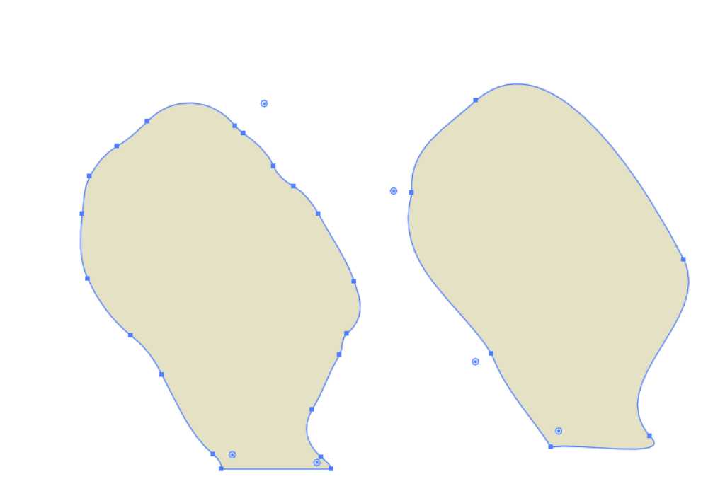 **left: image trace result, right: simplified path
Photoshop
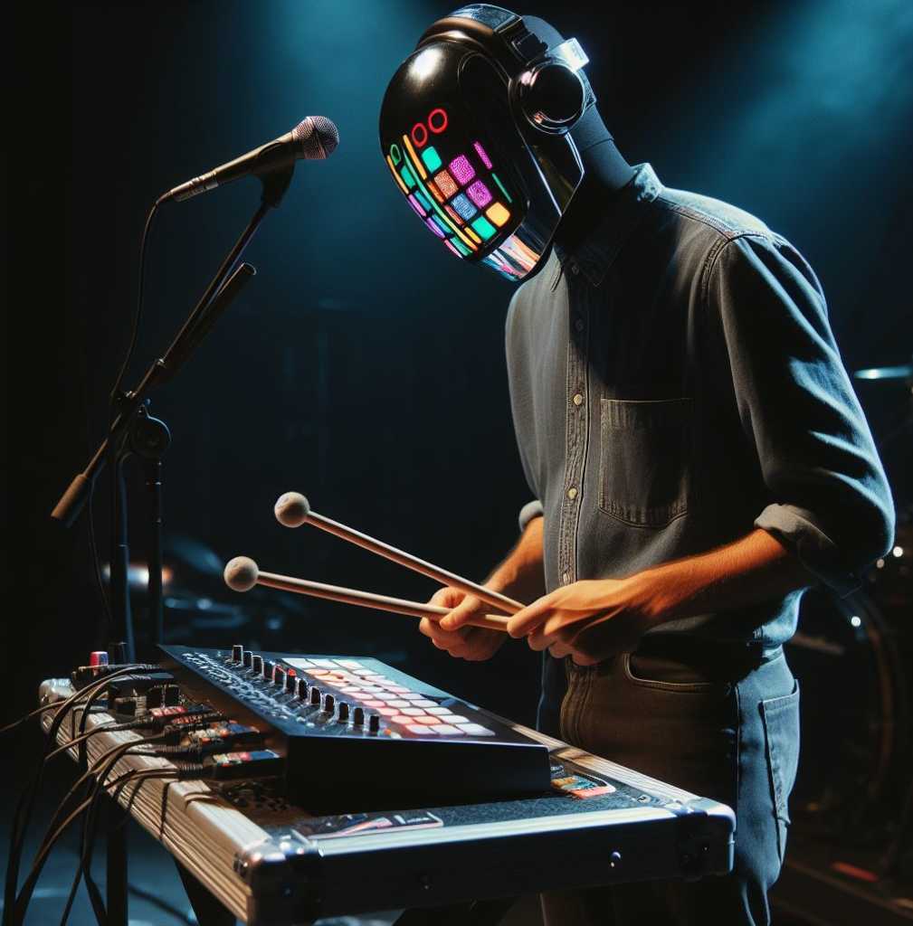
I’ve used photoshop a lot in the past. So I’m quite OK using it. For this week I used it to combine an AI generated image with my Blender rendered Marimbatron. The original:
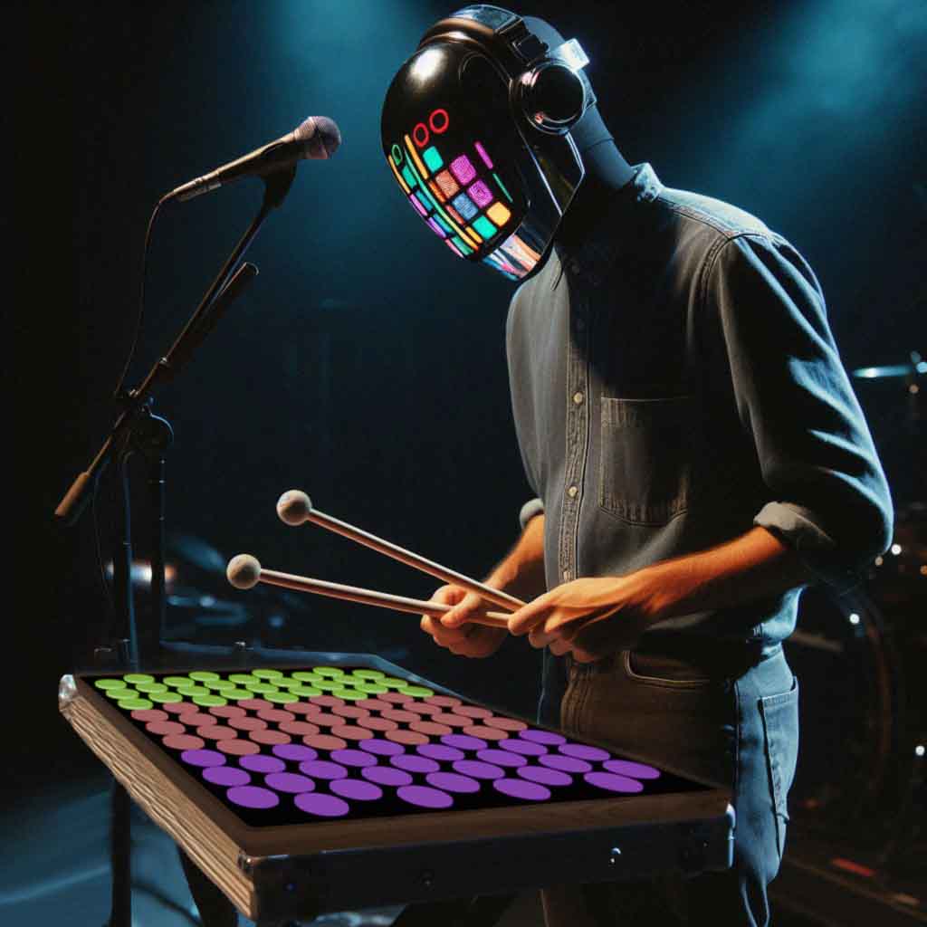
And the result:
3D product development
Saco gave us a training on product development strategies. from an engineering perspective
Basic steps are:
- Functional requirements
- (conceptual) design -> divide required functions and assign them to part of your design
- engineering -> electronics and mechanical
- drawings and specifications
The product design can be divided into functional breakdown structure and product breakdown structure:
- FBS
- what the machine has to do
- which functionality
- which can be combined and which have to be separated
- PBS
- what the machine looks like
- which parts and (sub) systems your need
- how the machine can be built5
- Logic breakdown of the product in assemblies and subasssemblies
- helps to manage interfaces between parts
- Helps to make risk assessment (FMEA: failure mode and effect analysis) -> what will happen to the product if … -> risk x costs = risk factor
Saco uses the V-model for this. This is something that we use at the Saxion University as well, so I’m familiar with that. The V-model is used to set requirements and specifications on different levels and at the same time set verification and validation tests at the same level. Everything will have to be checked on all levels.
In 3D modeling the sequence of events is very important. If you choose a “wrong” sequence from the start, you’ll end up with lots of extra work when you want to make changes.
3D software tools
Saco made a nice comparison between several 3D software tools. Here you can find it.
Fusion is all about solids.
Rhino is all about surfaces.
Blender is all about meshes.
OpenSCAD is all about programming.
Fusion
Fusion is all about solids. This is different from e.g. Rhino which is all about surfaces.
The browser is quite similar to a product breakdown structure.
Interestingly you can create G-Code directly in Fusion to drive CNC machines. Fusion has more milling strategies. V-carve (as used at Waag) and Carbide Create (used at Fablab Enschede) are quite limited. I want to try 2.5D CNC milling so I’m going to check this out. Use the manufacturing view in Fusion for this.
Fusion can create simulations using joints.
If you want to insert ready made components of standardized parts: insert - insert McMaster-Carr.
Use Fusion for 3D printing: Utilities - Make - 3D print
Use Fusion for CNC milling: use manufacturing workspace
Use Fusion for Lasercutting: rightclick sketch - save as DXF (update note: use the shaper add-in)
If you have a 3D design in Fusion 360 and want to slice it for lasercutting or CNC purposes, you can use the depricated slicer.
Rhino
We got a workshop on Rhino from Asli Aksan (class.textile.academy.org/2024/asli-aksan teaches at textile fabacademy).
There are different types of modelling:
- Mesh -> uses edges and vertices
- Nurbs -> This is what Rhino and Fusion use. It’s a mathematical relationship.
- SUBD -> In between mesh and nurbs. It is defines using the cages around the control points.
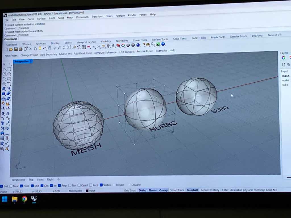
Rhino started as Nerbs modelling. It is not good at mesh modelling. Now they’re going more into SUBD modelling.
There are multiple degrees to define a curve. 1 Degree is a straight line. More degrees adds more control points and you’ll get a smooth curve.
Objects in Rhino are surfaces only, no solids. So a boolean operation of a 2D face with a 3D design can only work if the 2D face goes all the way through the 3D body.
To do parametric design in Rhino you can use:
- Python script in Rhino
- Rhino script
- Grasshopper -> a “plugin” which comes with Rhino. Grasshopper uses Rhino for visualization. It looks like this:
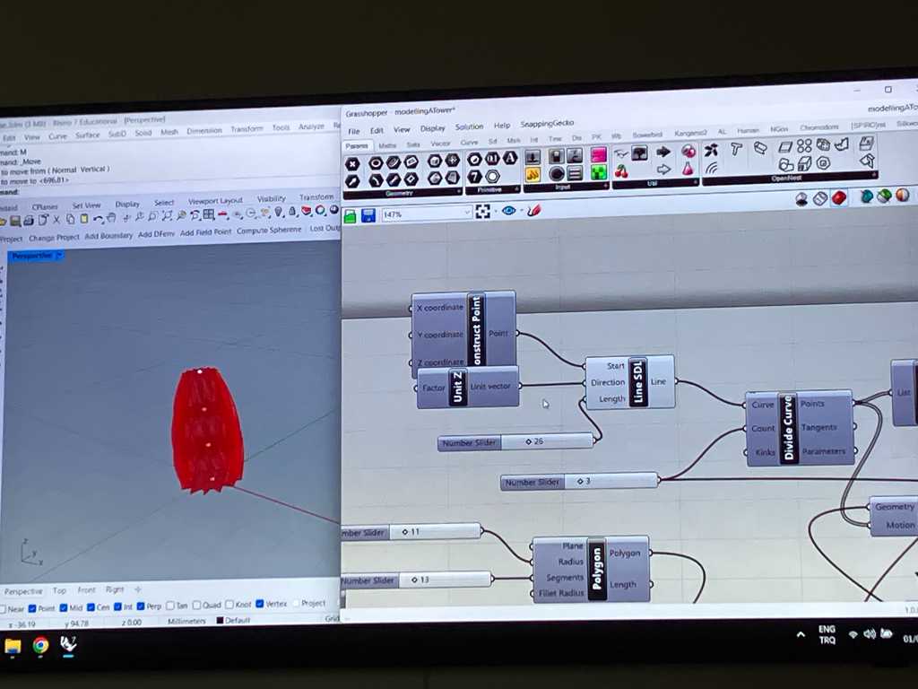 Left: rhino, Right: Grasshopper
I recognize the way Grasshopper works from MaxMSP, which I use quite a bit when making music in Ableton. So it uses flows of components: boxes that are connected with lines over which data “travels” from one box to another.
You can create stuff fully in grasshopper using the Geometry menu. You can also design in Rhino and link certain point to Grasshopper.
To create a box:
- Primitive -> add BoxRec. This component needs a R (rectangle input) and a H (height, which requires a number).
- Rec2Pt -> this defines a rectangle. Connect this to the R input of the BoxRec.
- By default, certain values are set by default. Change them by adding a number input to P, A, B, R inputs of the Rec2Pt. P = base plane, R = corner radius to create fillets, A & B = set the length of the sides
- Input -> Number. Connect this to height of the BoxRec. Now you can set the height of the box.
You can see the component in Rhino, but this is just virtual. You have to “bake” it. Rightclick on a component and click bake. Select the Rhino layer where it needs to go to and click OK.
Use ctrl-alt click on a component and it’ll show you where this box came from (how it was created).
Hover over a box input or output to see help information.
You can connect an output to multiple inputs by holding shift. There’s a hierarchy. Sometimes the order of connecting things to a single input matters.
If you want to know what comes out of a component (like a “print”): use a panel component.
If you doubleclick on an empty space you can type the name of the component you want.
Display -> draw full names -> will display the full name of components inputs and outputs.
Components are computed from left to right! So the order in your design matters.
OpenSCAD
Edwin Dertien gave us a workshop on OpenSCAD. The tutorial is here.
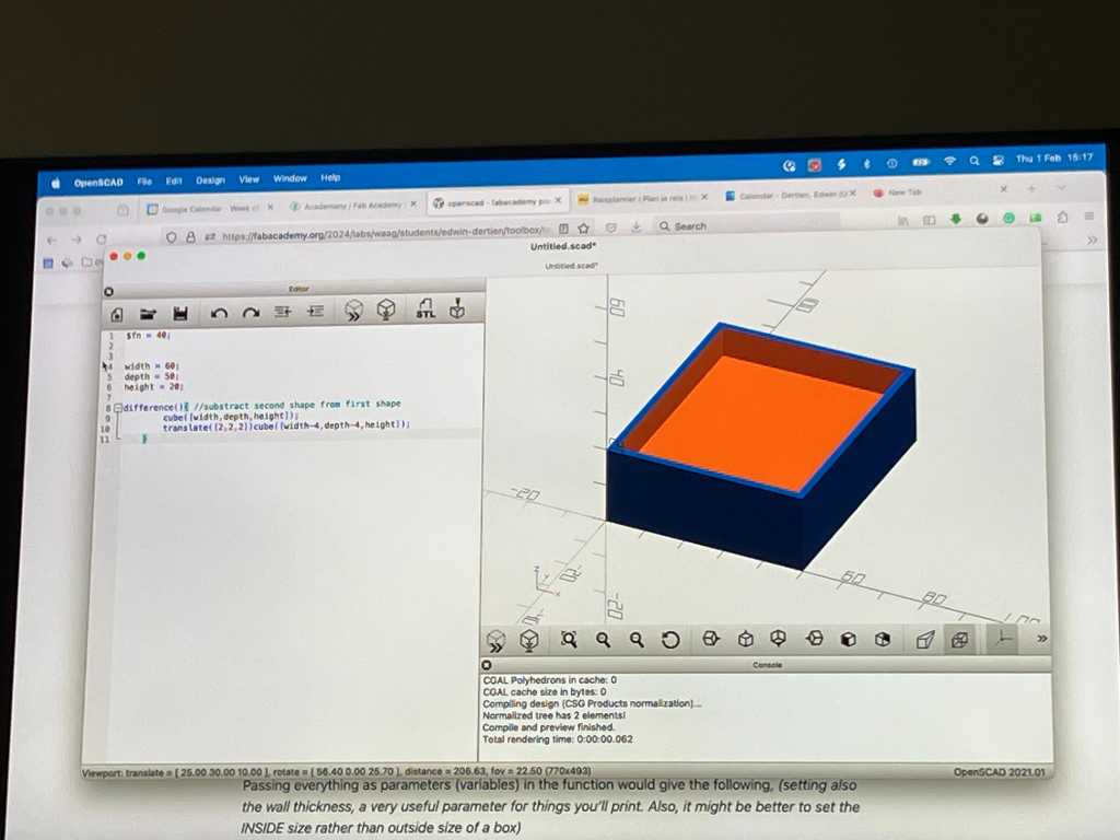
OpenSCAD has a very clean user interface:
- a code editor. It uses syntax similar to C. It has autocomplete.
- a visualizer
- a console: will give error warnings
It exports directly to STL. You can import STL and vector drawings. But there are no “helping” tools to aid in mating bodies, positioning, etc.
By default openSCAD is mesh based, so the visualizer looks kind of blocky (if that’s a proper word). You can make it look better by adding $fn = 40; as the first line of your code.
To create a box, this is the code:
difference(){
    cube([40, 50, 20]);
    translate([2, 2, 2]) cube([36, 46, 26]);
}
The cheatsheet (help - cheatsheet) is the best way to know what commands are available. It’s about 1 A4 printed, so not that much.
This can be parametrized easily just like any other programming language.
If you want to reuse parts, you can define them as a module:
box(40, 50, 60, 3);

module box(width, depth, height, wall){
    difference(){
    cube([width, depth, height]);
    translate([wall, wall, wall]) cube([width - 2 * wall, depth - 2 * wall, height  - 2 * wall]);
    }
}
In openSCAD there’s no such thing as a loft, but you can use hull. This acts like a boolean function. First shape stays, following shapes are substracted from it. So hull will act like a balloon around objects: it will show the outer shape.
There’s a VSCode plugin for openSCAD (called openSCAD). You can now program in VSCode and preview your 3D design in openSCAD.
OpenSCAD can import STL files. This is useful for example to create a box around electronics design made in KiCAD. KiCAD can export as STEP. Use freeCAD to convert this to STL. Then open it in OpenSCAD.
Now you can design a case around it.
You can translate a 3D shape into 2D for lasercutting or CNC milling using the command projection. You can use this to import an STL file and slice it into parts :-)
You can also translate 2D to 3D. The magic command is called linear_extrude. So you can import a SVG vector file and extrude into 3D using this method.
Freecad
Henk gave us a short workshop on Freecad. Freecad uses workbenches to get work done. Every workbench has it’s own set of features and things it can do. For example the Sketcher workbench, which is used to sketch.
The way freecad works is very similar to Fusion. But seeing it live, it feels a lot less polished, so although I do advocate open source as much as possible, I think I’m going to stick to Fusion for this.
Blender
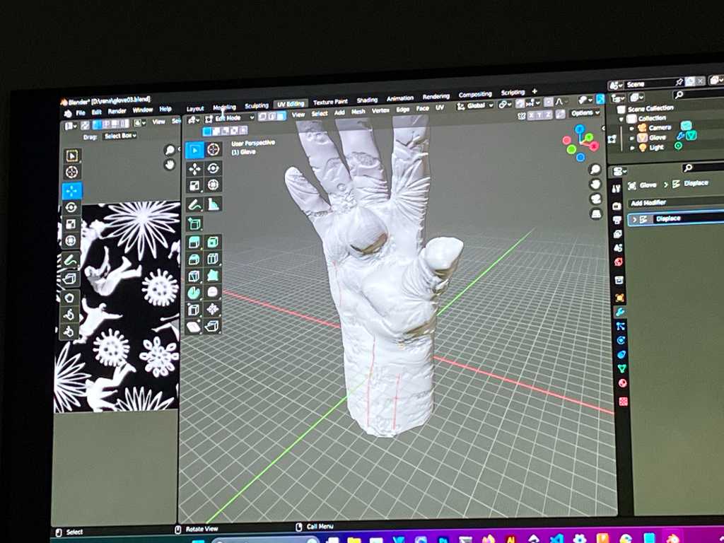
Michelle gave us a short workshop on Blender. Blender is a good tool to edit mesh networks.
She combined several 3D tools to create cool stuff. Like design something in Fusion and add texture in Blender.
Blender has several modes. Each mode gives different tools to do operations on your object.
Blender has a sculpture mode with different tools. It treats the model as a piece of clay.
Modifiers are important. modifier menu -> add modifier. /These modifiers can be thought of like the adjustment layers in Photoshop. They will have to be applied (arrow down icon -> apply) to actually render it in the mesh.
Interesting modifiers:
- subdivison surface: will make the surface more smooth at the cost of lots of CPU.
- Remesh modifier: creates a unified mesh, useful if you want to edit the mesh in detail
- boolean operation modifier
- Displace -> add textures from images as height texture to your mesh
In Blender everything is in meters. Arrgg. Fortunately you can fix this:
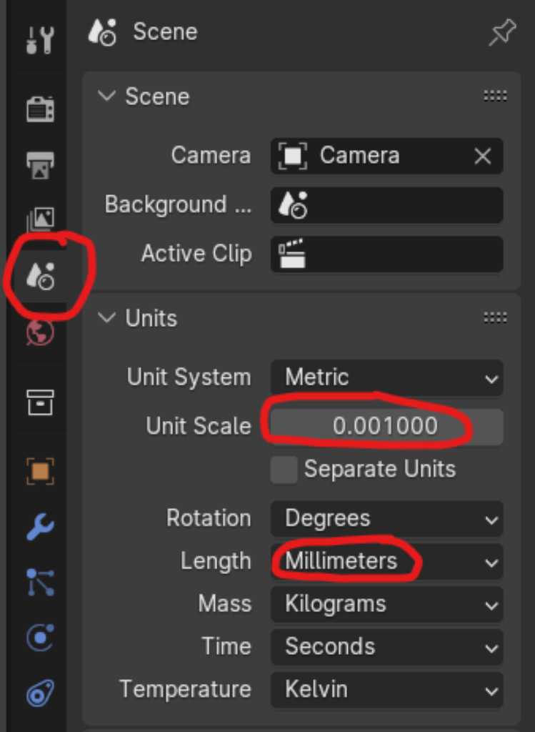
Go to the Scene pane, go to the Units section, set Unit Scale to 0.001 and Length to Millimeters.
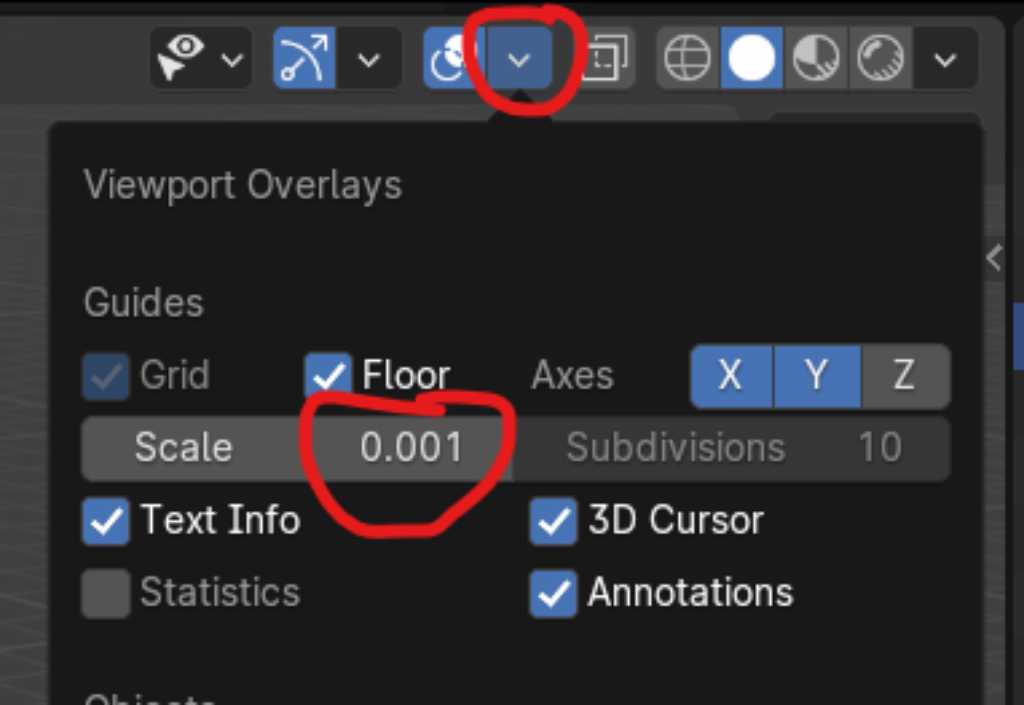
Do the same for the grid by going to the viewport overlays and change Unit Scale to 0.001:
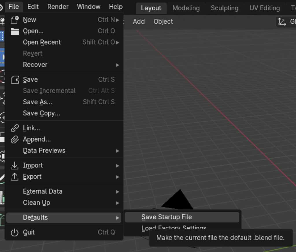
To save this as your default setting, go to File - Defaults - Save Startup File.
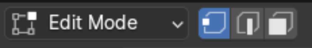
In edit mode you can select what to edit (edge, point or face):
If something is selected, press G to grab and move it using the mouse.
Next type x, y or z key to fixate movement to this axis.
With tab you can quickly switch between edit and object mode.
Move an object by going into object mode, select, press G.
Scale shortcut: s
Extrude shortcut: e
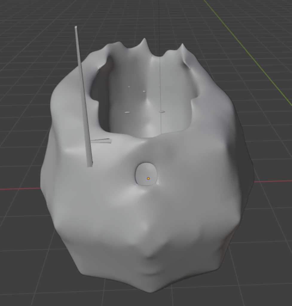
Nice first try :-)
In sculpt mode, check the dynamic topology mode so blender creates new surfaces.

Saco pointed us to this nice instruction for Blender: http://feadi.de/tutorials/blender/
Final product design
Because I knew this week my time would be limited, I already started designing my final project in Fusion a week in advance.
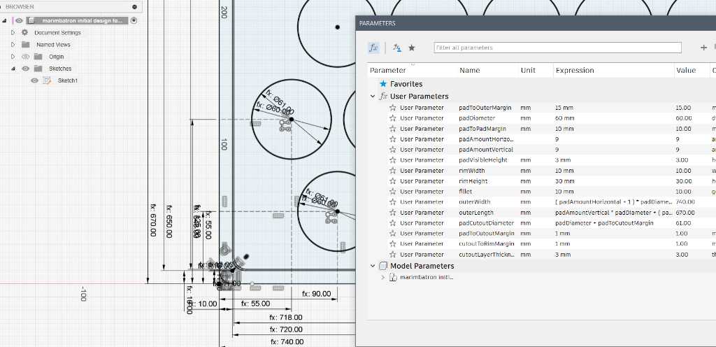
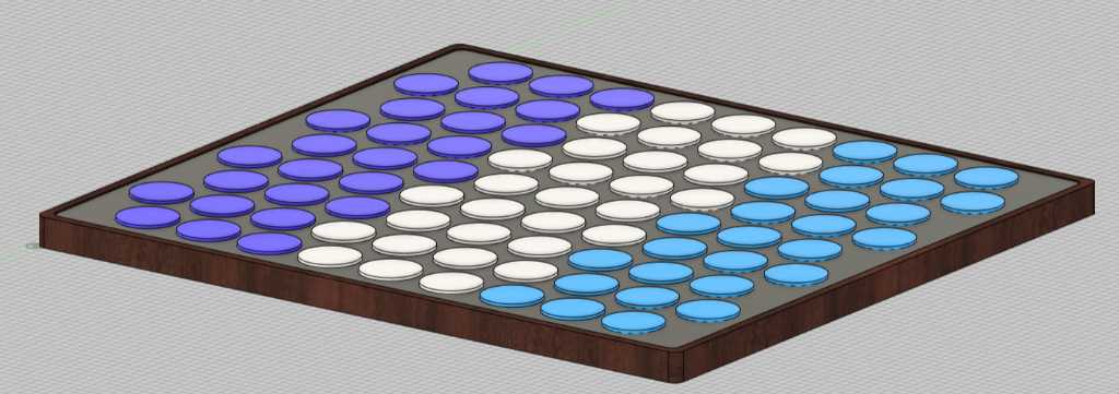
I’ve set up a initial design using parameters to define sizes in the sketch. Next I use the extrusion command.
I added one circle which is going to be the pressure sensor. Next I used the Rectangular pattern to add multiple circles (with a parameter for the amount of circles) that have a certain distance in between (again a parameter). This pattern is set in such a way that it immediately creates all the lines of circles (so rows and columns in one go):
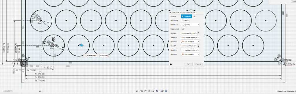
Same thing for the second line of circles, with a different offset from the edge of the case.
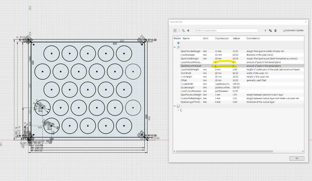
Next I used more parameters to define offsets from the edges of the case to the circles. So the width and height of the case depend solely on the amount of pressure sensors.
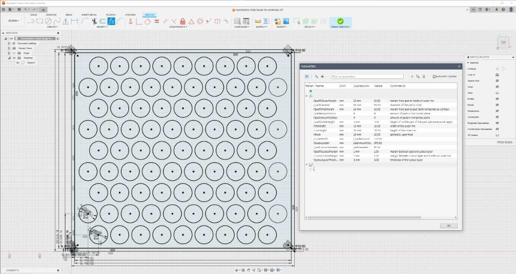
Now I can play with the parameters to get it to what I want:
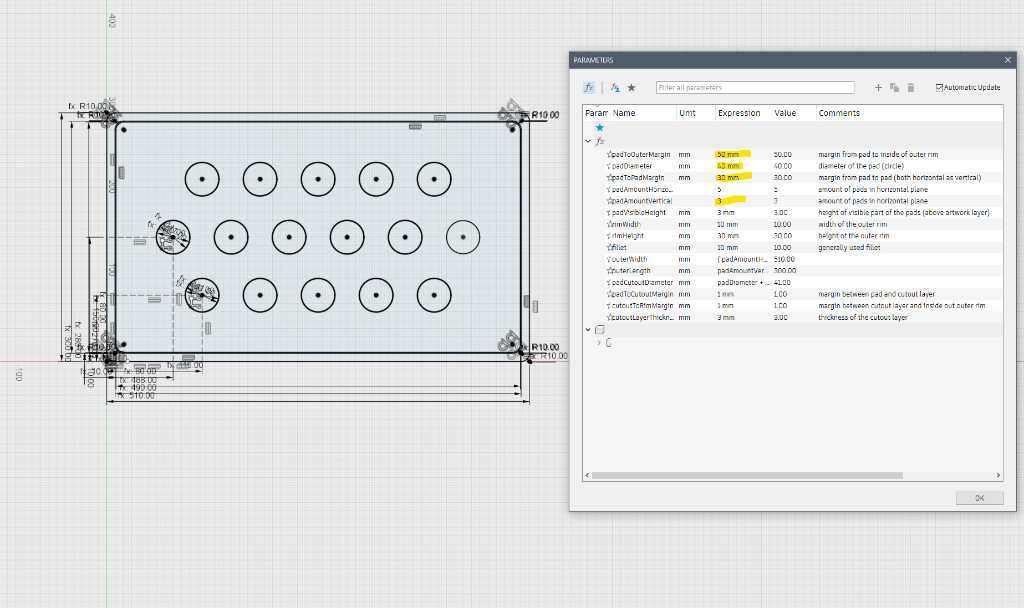
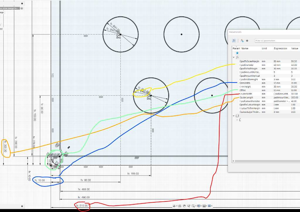
The way for this to work is that the features in this sketch are constraint to points and lines that have distances that are parameters:
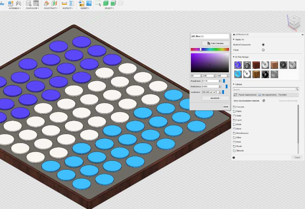
Next I extruded the parts and gave them a material appearance. Extrusion is just 3 simple steps. Material appearance is done by pressing keyboard shortcut “A”:
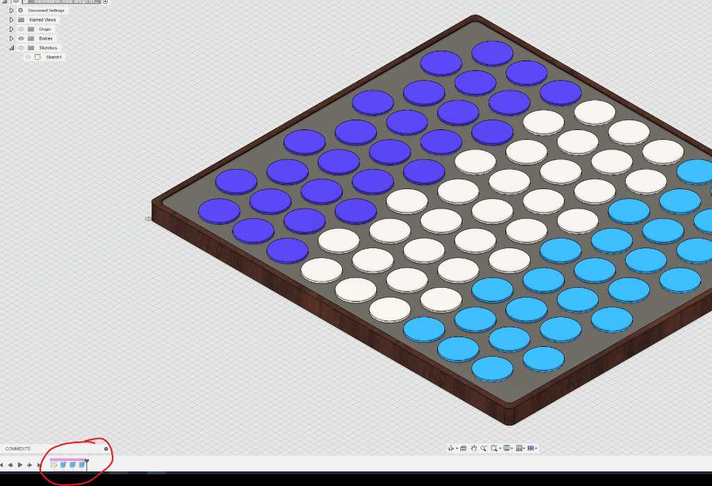
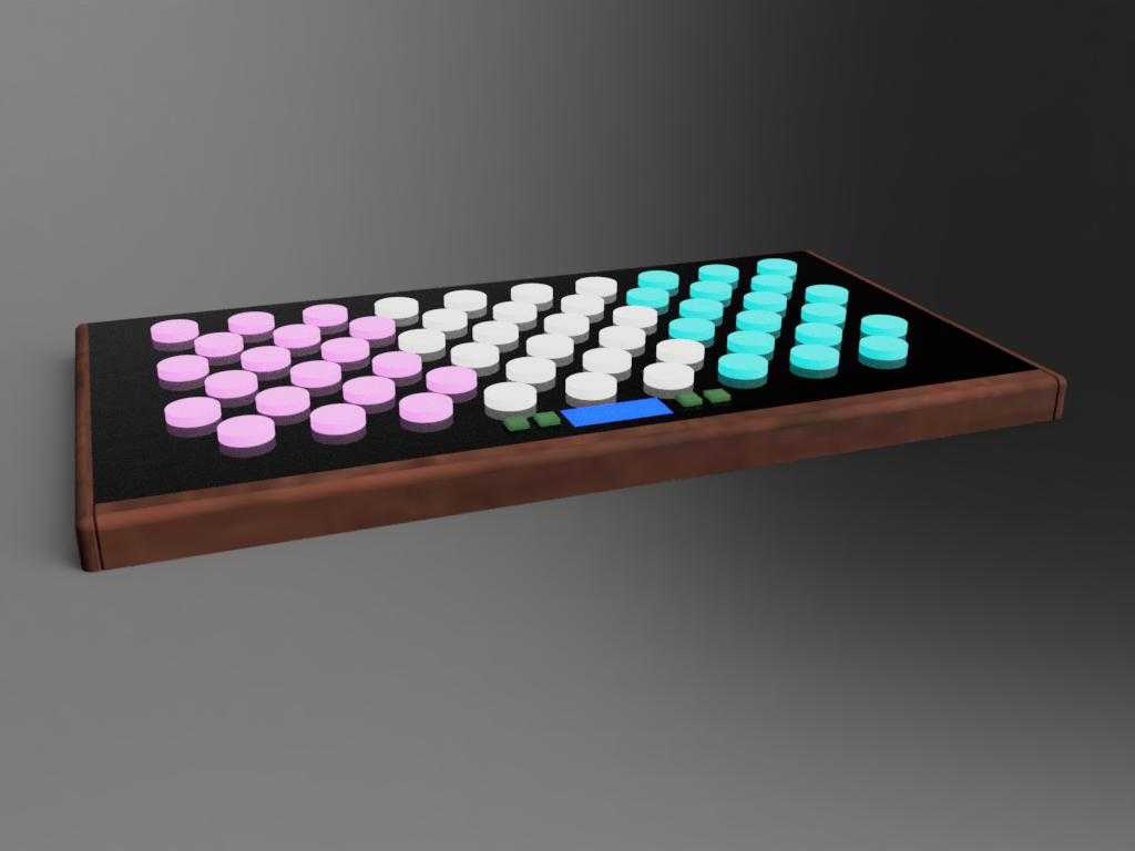
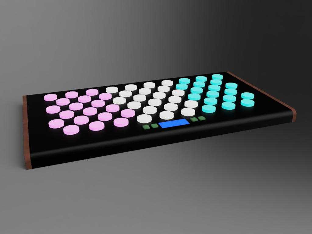
This week I played a bit more with different variations of the design and rendered examples:
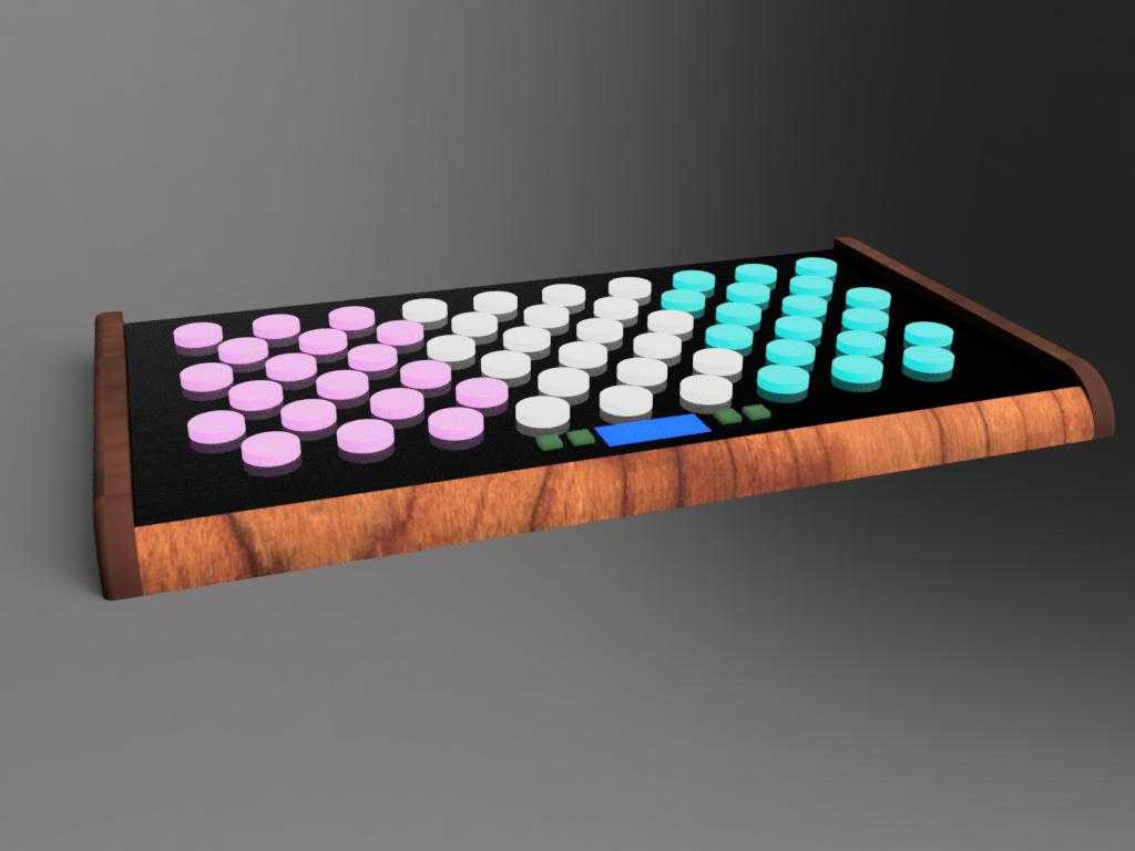
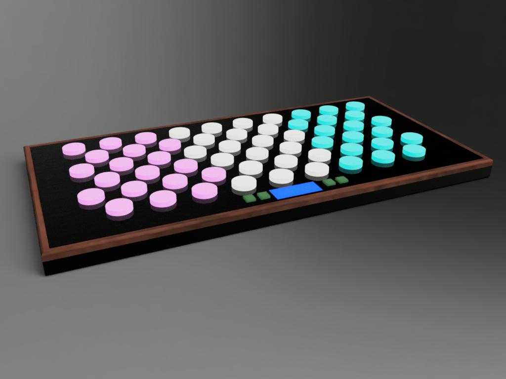
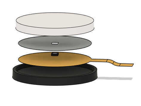
I also made a design of the pressure sensor idea that I have. Again using parameters. Using the Animation workspace in Fusion you can easily explode assemblies:
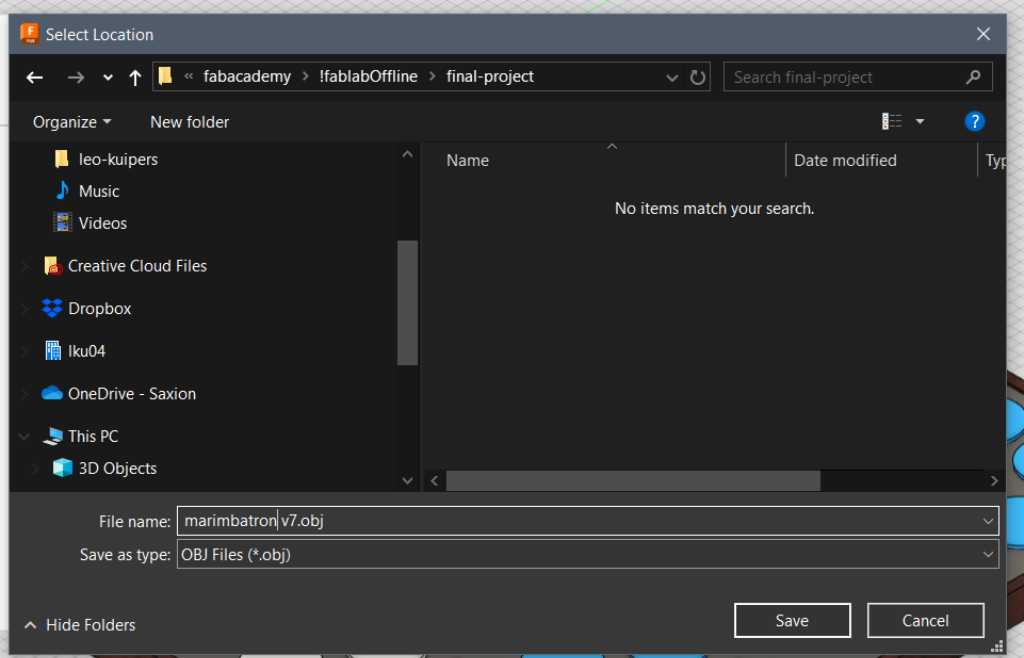
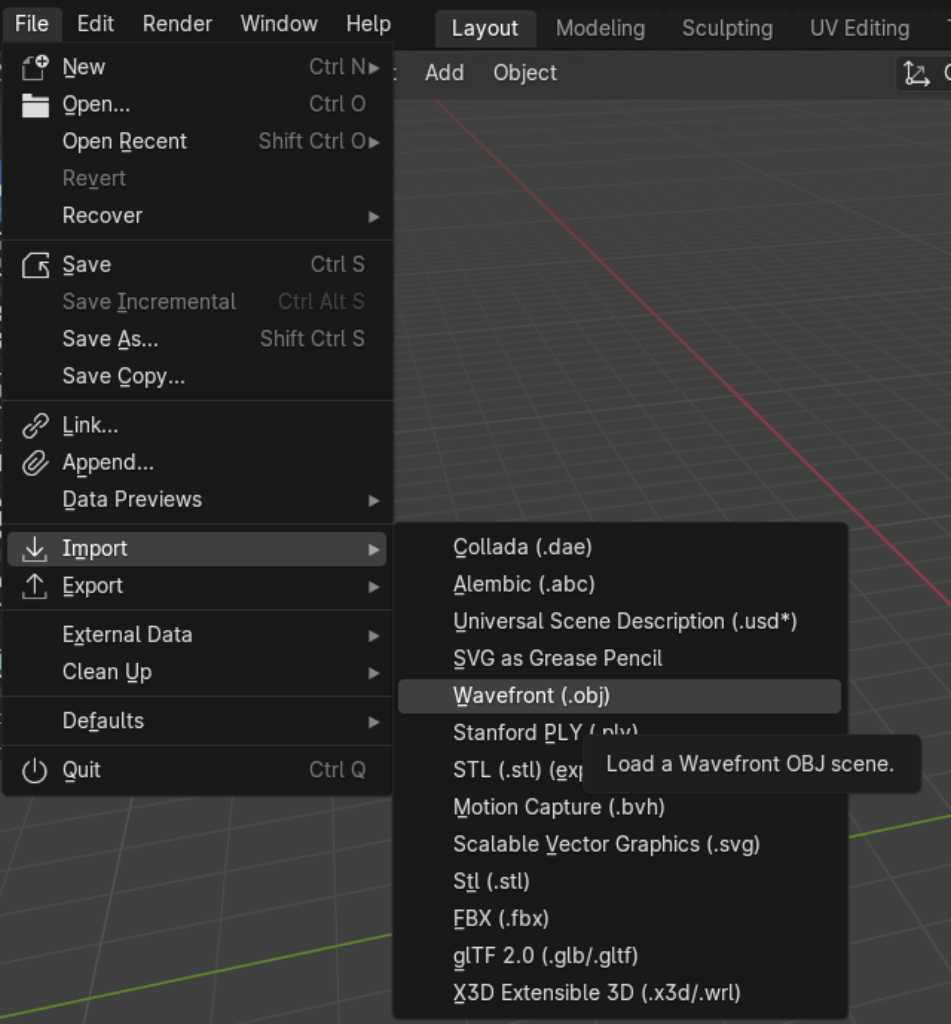
Next, I exported my fusion design as obj file (file - export - obj). This obj file could then be imported into Blender.
I used this youtube video by Kevin McAleer to check how to import obj files and render it. Parts of the text below are taken from this video.
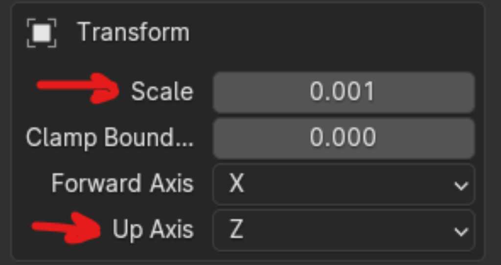
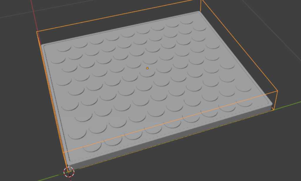
First the import. The important part is to set the Z axis as the Up axis and scale to 0.01 (in the import screen). Setting the scale is only required if you haven’t set it already in your default file (see Blender section above):
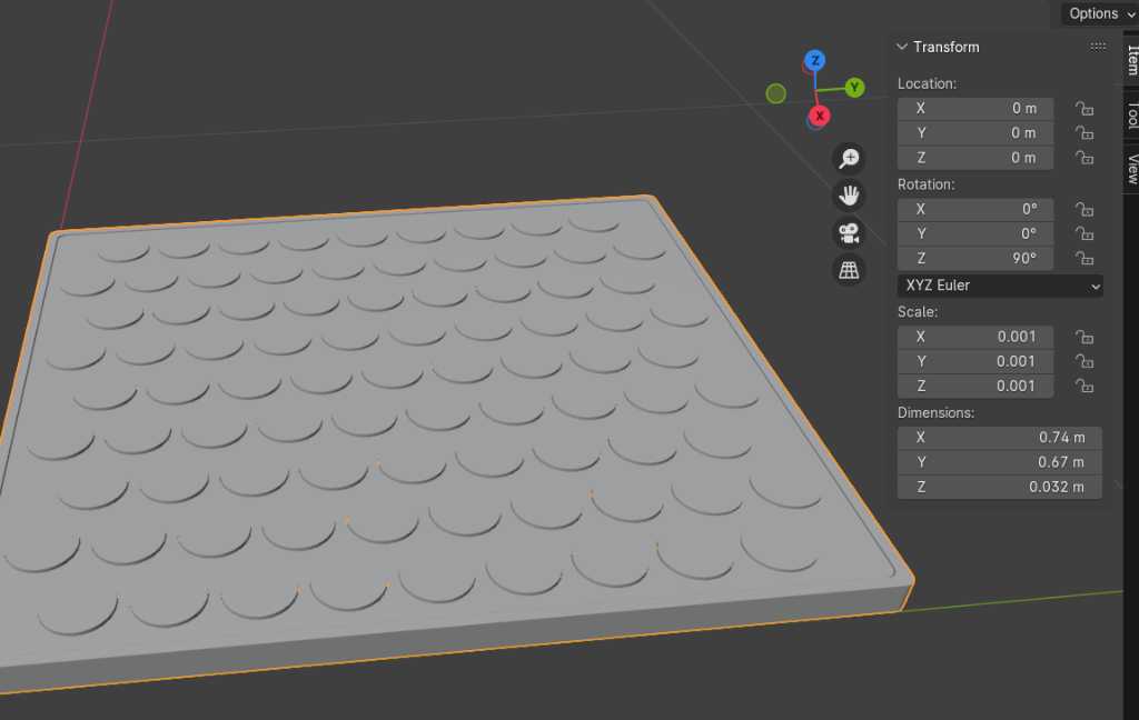
This looks nice and grey. So let’s edit the textures. I’ve already added textures in Fusion using the appearance window (shortcut a) so I can see these textures in Blender. They’re just grey. So I need to edit them:
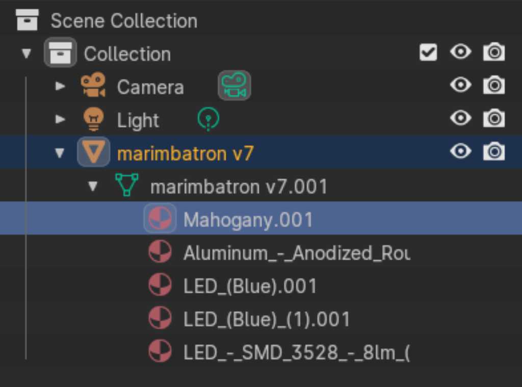
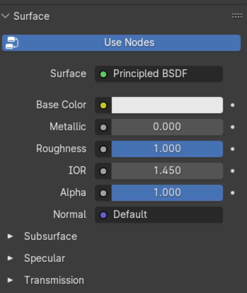
Clicking on any of these layers with this red beachball icon, I could change the appearance in the surface window down below:
A better way to change these surfaces is to download blendfiles from the internet and use them as material. A good site is https://blendermada.com/ and polyhaven.
To organize these materials, you can install the Library VX add-on, by going to file - preferences - add-ons - Material: Material Library (Material Library VX) and check that one.
Blender has different render modes: Wireframe, Solid, Materials and Rendered. You can swap between them using the icons in the top right: 
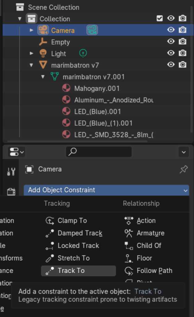
Blender uses a “camera” that allows you to see the object. By using “track camera” you can place a camera, lock it to the orientation of the object and next you can rotate the camera while always showing the object.
This is done by constraining object to an empty. Here are the steps:
- Create an empty cube by pressing
shift-a -> empty -> cube. - Select the empty cube in the Scene Collection area and press
gto grab it - Place the empty cube over your object. Press
sto scale if needed. - Click
camerain the Scene Collection. - Click the
constraintstab. - Add a new
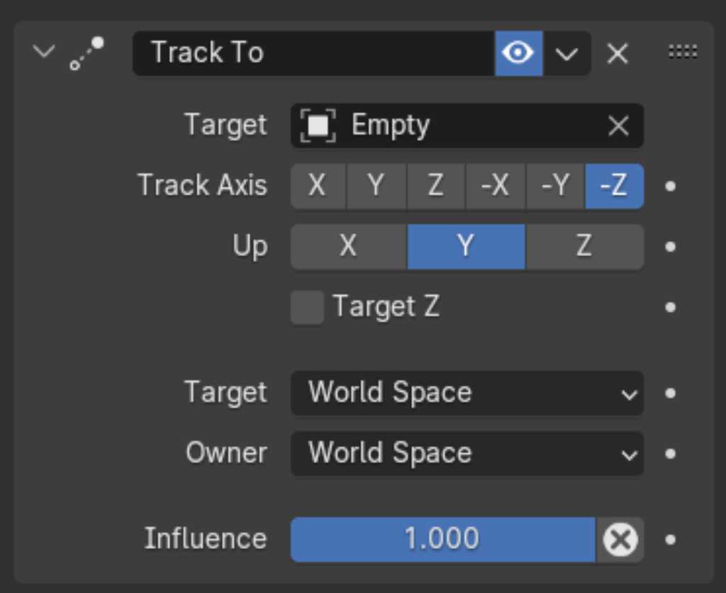
object constraintand selectTrack to - Change the target to the empty cube that was just created
- Change
track Axisto-Z - Change
UptoY
On the numerical keypad, each digit represents a view from a certain angle. Pressing the 0 will show the camera view.
You can position the camera and animate by using the timeline at the bottom of the screen. Add keyframe, change the position of the camera by clicking it in the Scene Collection and pressing g, add keyframe again, etc.
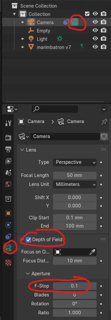
Another cool thing is to add depth of field (bokeh) to the camera by clicking the camera icon, check depth of field option and change the F-stop to 0.1 (extreme bokeh).
Also a very important setting is the Clip end which you can see in the screenshot below. If your render looks cutoff, you should increase this.
According to the tutorial of Kevin McAleer, you should also change the renderer to Cycles. Blender defaults to Eevee renderer, which is fast. But Cycles produces higher quality. Change the renderer by clicking the camera in the Scene Collection, choose cycles as render engine, Render max samples to 500 and select denoise.
Next I needed to adjust the lighting by clicking Light in the Scene Collection and changing its position, brightness, etc.
To render, press F12. I wanted to render transparently, so I used this guide to learn how to do this: properties panel - render properties tab - film section -> check box transparent.
Now let’s see if I can fit a Blender rendered image of my Fusion modelled final project in an AI generated image using Photoshop :-)
AI source: Copilot. Prompt: create an photograph of a rock band on stage. The frontman wears an artistic mask, similar to the ones of deadmou5 or daft punk. The mask is bright and very colorful. He is standing up straight behind his instrument. This instrument is a square device that looks like a novation Launchpad and a Roland spd-sx with round pads. the musician hits his instrument with two mallets. the instrument is placed on a stand similar to a stand for a synthesizer. the mallets are clearly visible. in the background there’s a rockband accompanying the musician. the photo is a full shot showing the frontman, the band and the stage. The photograph is high quality, full-color picture, DLSR with bokeh. the photograph is taken from a front angle as is the photographer was in the audience.
Link to repo
Fusion design of Final Project: marimbatron initial design for renderings v7.step
Blender file to render Final Project Fusion file: link to gitlab here
Photoshop file unfortunately not available anymore…
What I learned this week
Successes
Lots of software tools out there. From the ones we’ve tried, I like blender the most, but what a big piece of software it is. I can imagine this can easily become ones day-to-day profession. I only scratches the surface and am very impressed.
OpenSCAD still seems interesting. Although I find the visual appearance of Fusion to still be the main reason to stick with it. It’s good to know how openSCAD works though.
Fails & Fixes
Nothing went really terribly wrong this week. Obviously my ignorance has led me to a few situations where ctrl-z was the fix to my fail :-)
I had a nice git conflict though. I had to switch laptops because my other one was faulty. I though I had nicely moved all files and didn’t do a git pull. But git thought otherwise. So I had some conflicts. I didn’t know how to solve it so this page from the docs helped me. Now it’s all on track again.
Remember this for next time
Blender is cool. Watch youtube tutorials to get to know how to use it properly instead of just clicking around :-)