4. Mechanical movement
Joe and Leo are responsible for the mechanical movement of the pigeon legs and head.
Pigeon head movement
The movement of the head of a pigeon has been extensively researched.
It gave us a great idea how to mount the head-camera:
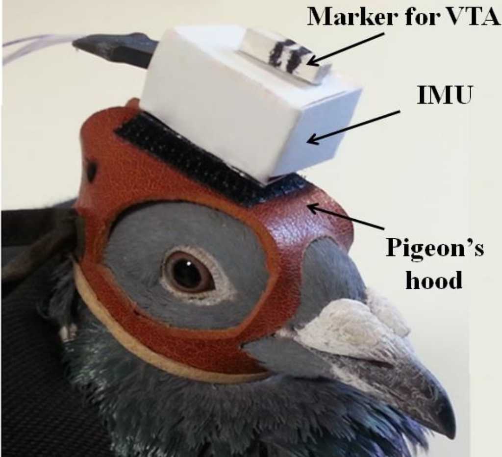
source:
Aldoumani, Noor & Meydan, T. & Dillingham, Chris & Erichsen, Jonathan. (2016). Enhanced Tracking System Based on Micro Inertial Measurements Unit to Measure Sensorimotor Responses in Pigeons. IEEE Sensors Journal. 16. 1-1. 10.1109/JSEN.2016.2586540. researchgate
Prof Reinhold Necker did quite an extensive research on head bobbing. You can find it here:
https://www.reinhold-necker.de/Head%20bobbing%20print.pdf
The forward and backward movements of the head are synchronized with the movements of the legs (Bangert 1960; Frost 1978; Troje and Frost 2000; Fujita 2002; 2003) source.
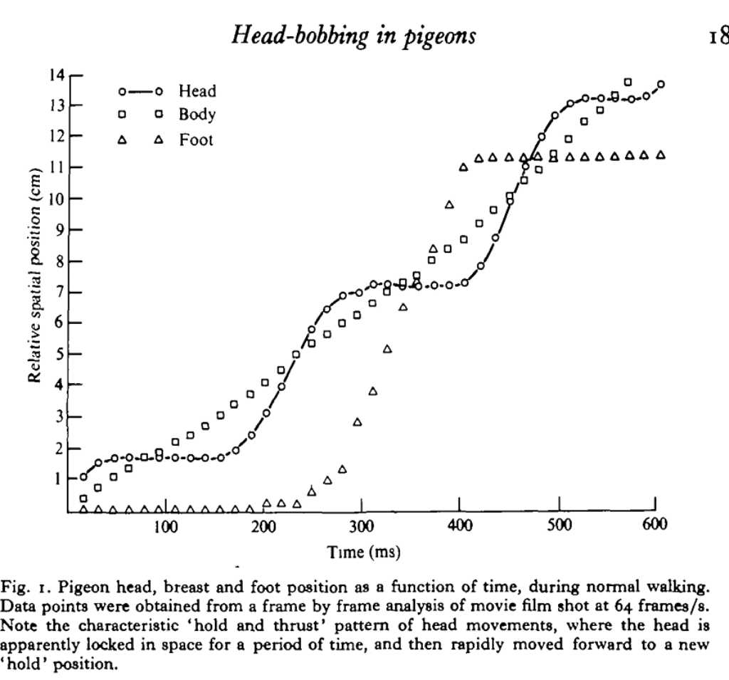
source: The optokinetic basis of head-bobbing in the pigeon, Frost (1979)
source: head bobbing
A great X-ray video of a quail walking can be found here: frontiersinzoology
4 bar linkage mechanics
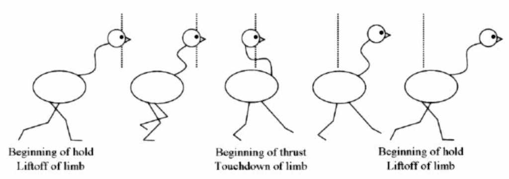
What we learn from this is that the head bobs every footstep. In reality the head goes forward and backwards using a neck movement, but the head stays level to the floor.
But we’ll first just make the head go up & down. Maybe later we improve on this.
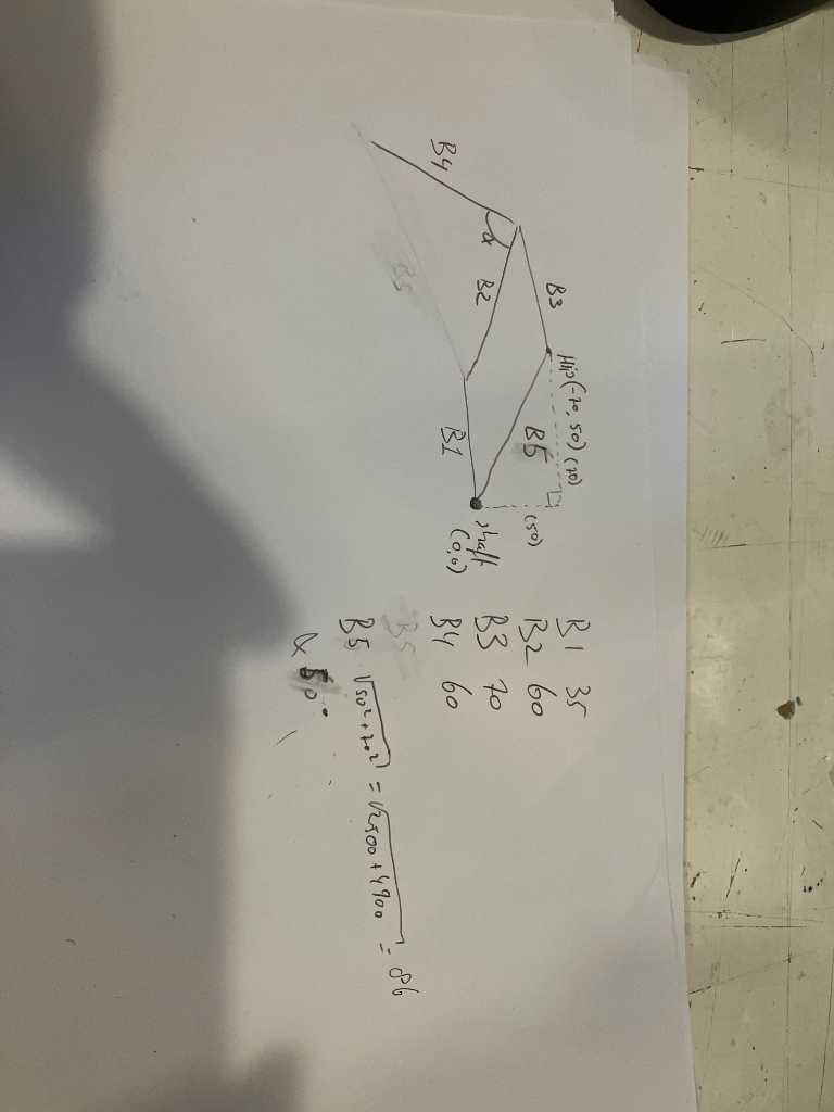
To simulate this, Leo used the https://www.diywalkers.com/4-bar-walking-linkage.html simulator. Find it at bottom of the page, use these settings:
- 4-bar size 15
- hip joint x -65
- hip joint y 60
- 4-bar B1 27
- 4-bar B2 61
- 4-bar B3 69
- 4-bar B4 73
- 4-bar B4 angle 64
- num legs 2
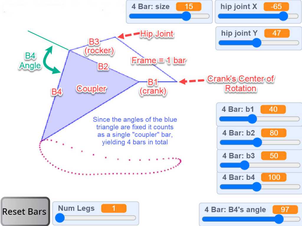
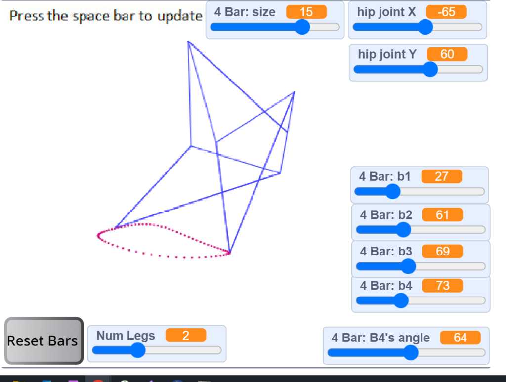
hip joint x and hip joint y are relative position to the crank’s center of rotation.
B1 to B3 length is 79.
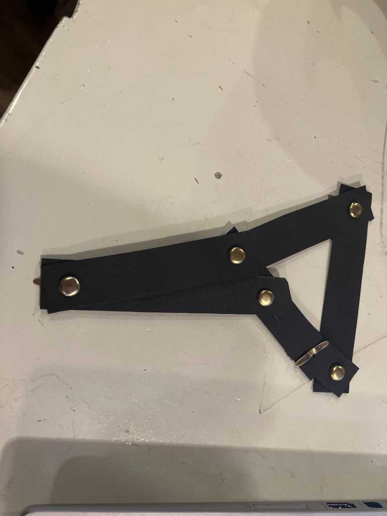
Next this simulation was cut out of paper to see if it works and if it could fit the pigeon sizewise:
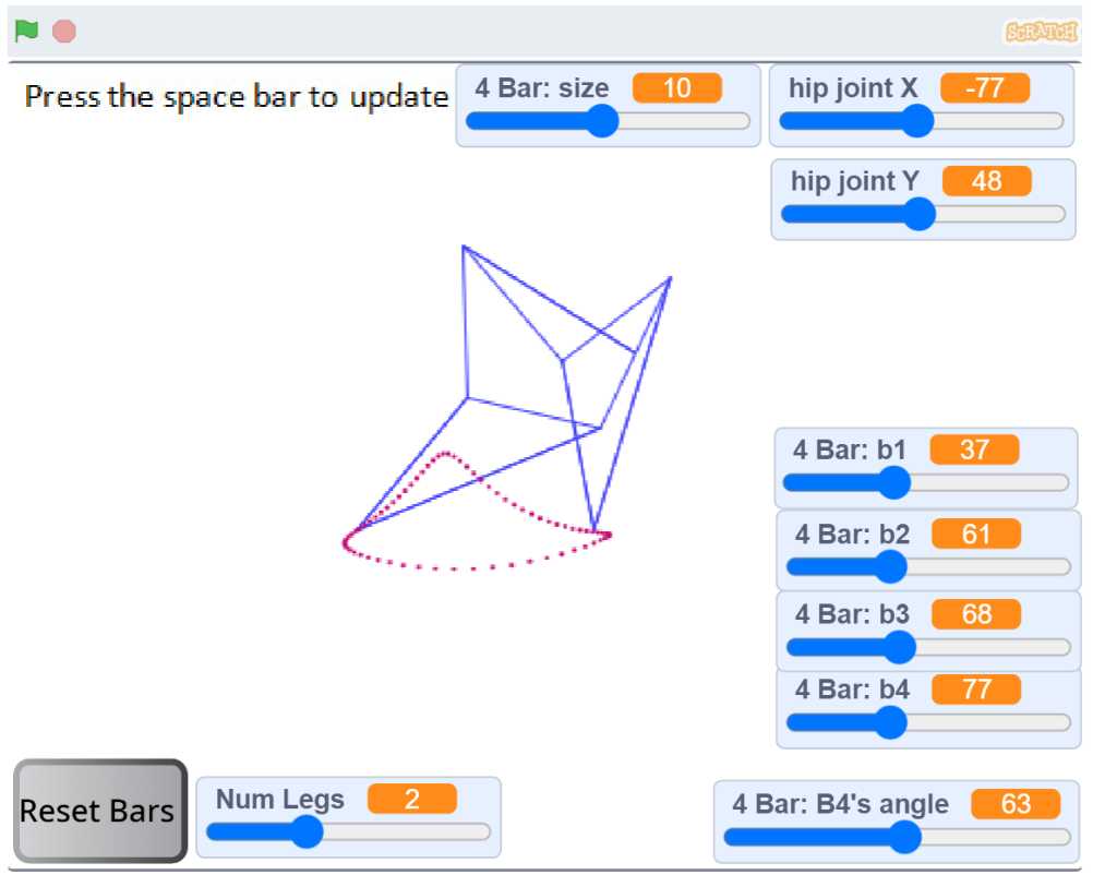
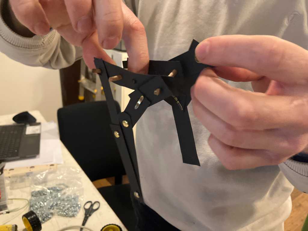
After some versions and more experimentation using the simulator, we found the following to be good. Leo created a 2-legged version:
The legs are designed in Fusion360 so we can lasercut it:
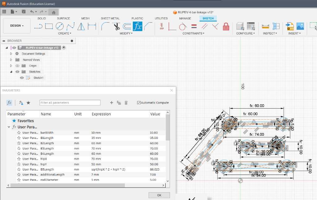
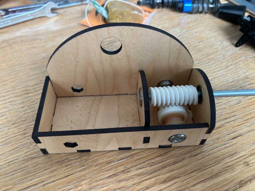
The legs and head will be driven by the robot. To get the motion of the drive shaft right, Leo created a wormgear, using this tutorial for fusion 360: https://www.printables.com/model/818869-worm-gear-tutorial.
Our version is parametric, so sizes can be changed and the model will update accordingly.
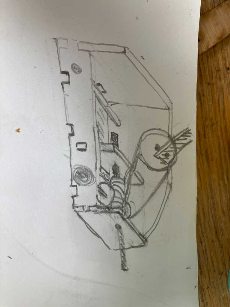
A good size for the gear is about 20mm. That will fit the pigeon using a fixture like this sketch:
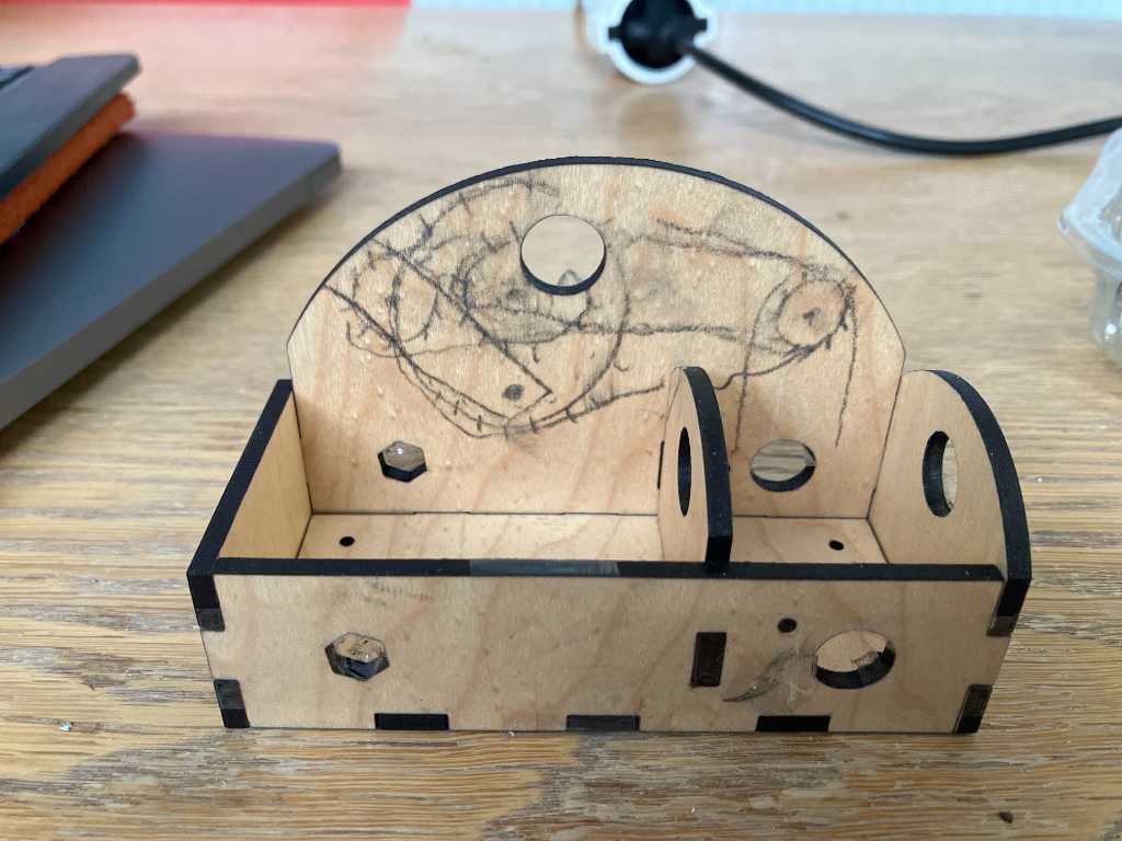
Fixture
This fixture is designed in Fusion360:
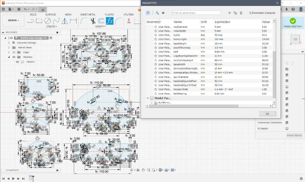
A few iterations of the fixture:
V2
V3
V4, now in combination with the legs:
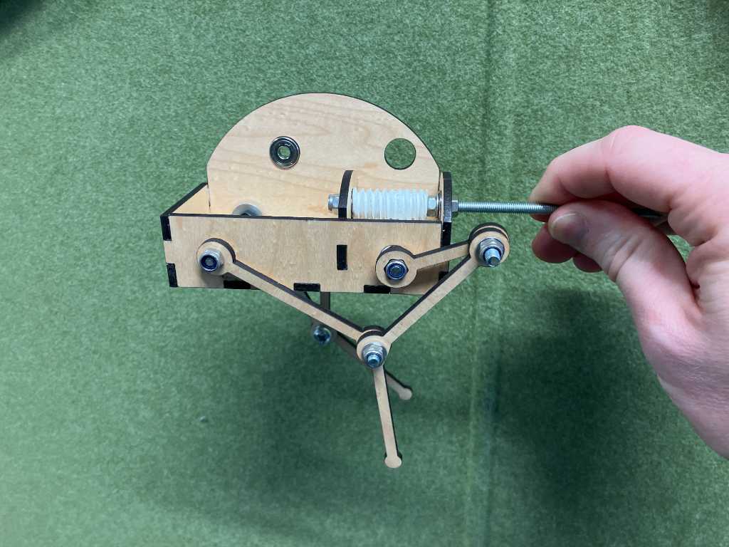 V5, with 6mm plywood instead of 3 for more strength:
Meanwhile, Joe is working on the head movement mechanics:
bevel gears
The reduction of the wormgear is far too much. The shaft will have to turn > 200RPM. The motor we want to use can’t do this. So new plan is to make new gears: Bevel gears instead of worm gear.
We took openSCAD gear library from this github page and added a little extension:
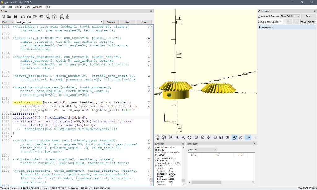
The part of the script that we added:
bevel_gear_pair(modul=0.635, gear_teeth=30, pinion_teeth=30, axis_angle=90, tooth_width=5, gear_bore=5, pinion_bore=4.5, pressure_angle = 20, helix_angle=0, together_built=false);
difference(){
translate([0,0,-5])cylinder(d=16,h=6);
translate([0,-11,-2.5])rotate([-90,0,0])cylinder(d=2.5,h=22);
    translate([0,0,-5])cylinder(d=5,h=10);
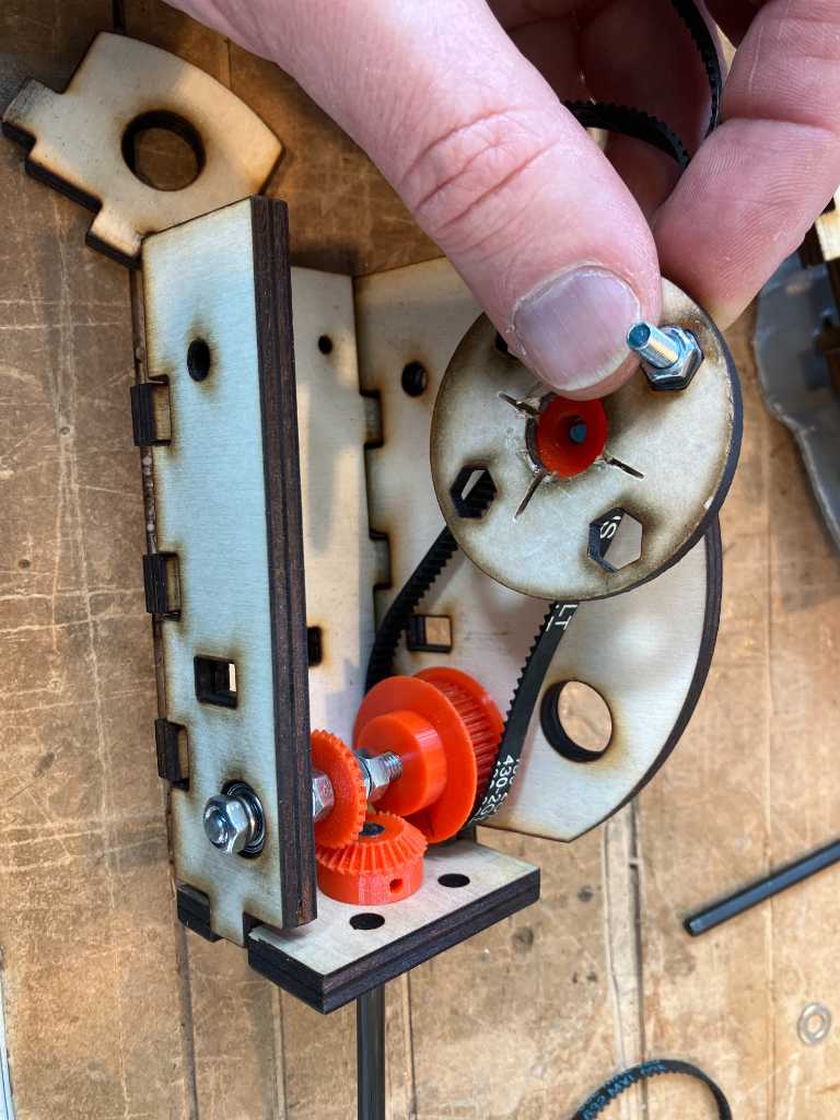
The bevel gears are printed using PETG on Bambulabs X1C. Also Timing belt pullies are printed. Joe was able to download a Fusion360 parametric model of timing belt pullies that allowed us to make them in 2 sizes. So we could get a 1:2 ratio.
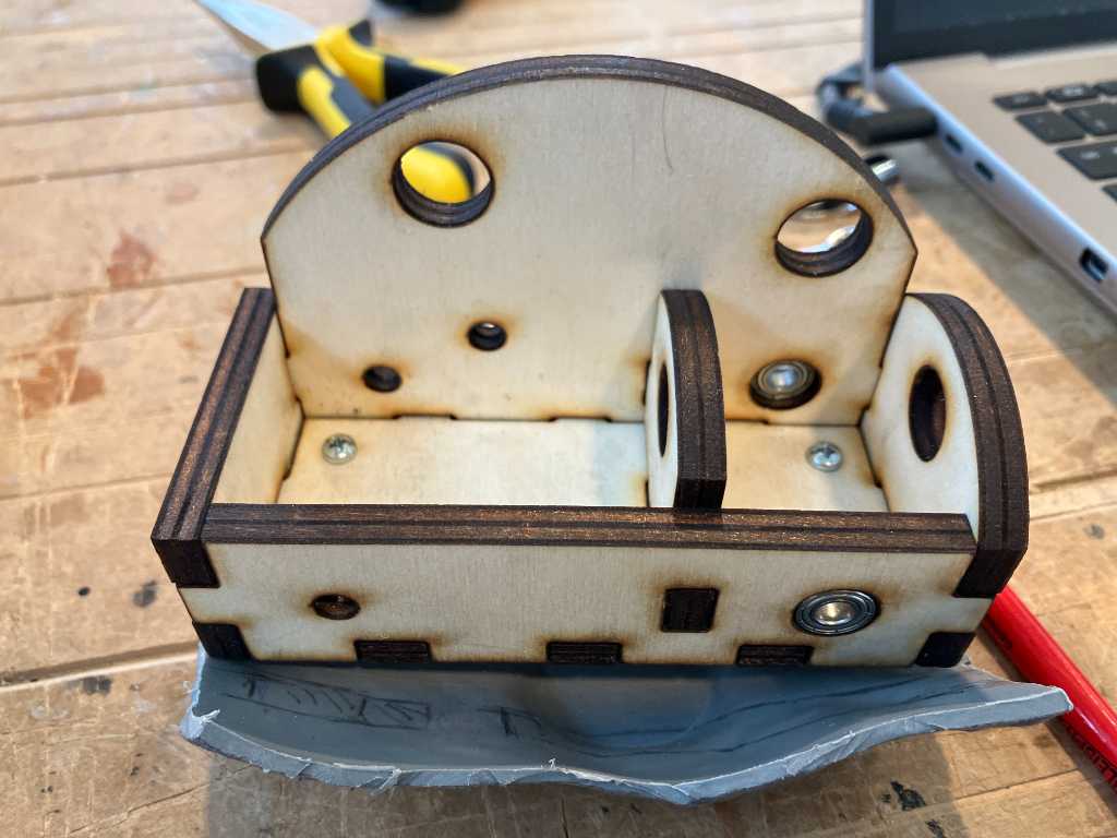
Another redesign of the fixture later, I was able to get rid of the inner piece of wood, allowing us to get rid of an extra pully. Now we have direct drive. Nice.
Finally after a lot of trial & error of the fixture we have a working unit:
The puppetmaster connector to the pigeon:
We need a block to get some distance between the pigeon and the holder that is mounted onto the robot. That’s fortunately easy to do in Fusion 360:
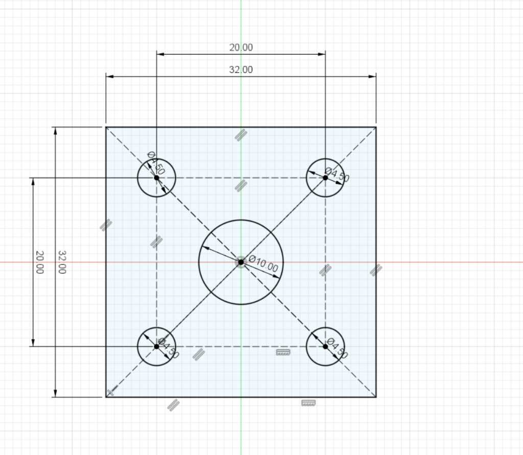
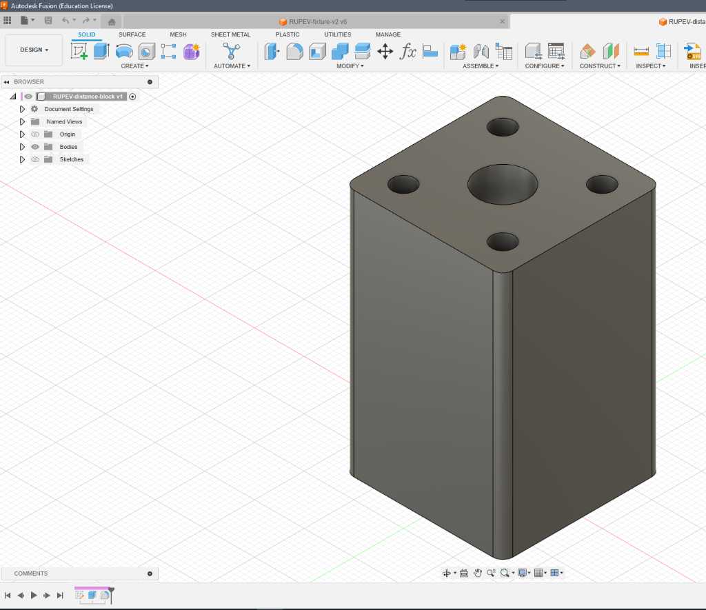
Printed this in nice orange PETG on the bambulabs. First time right. Nice.
getting things done
On the last day, I worked more on getting the mechanics to run smoothly. I cut a driving belt to length and glued it together, with another piece of rubber on top for extra fixation. This made it too stiff, so grinded that down again:
Now we continued to add the head so it could start bobbing. This is were we unfortunately ran into issues. The mechanics to pull the head up had too many degrees of freedom. Also the head was too heavy for the mechanics to lift up. The gears started to slip. We we’re able to get it bobbing a bit though:
But we had to decide not to bob the head unfortunately. So we attached it to a spring so it would wiggle a bit :-)
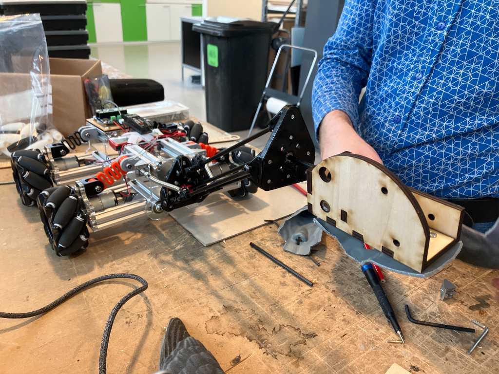
Next we attached the pigeon fixture to the robot, worked on getting the driving rods to the correct size and properly attached and then:
The final part is getting the body back on. Time pressure…
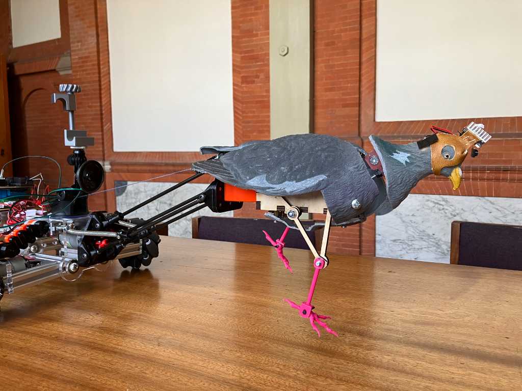
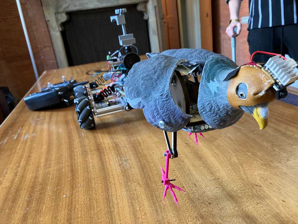
Eventually the body didn’t really fit anymore. It interfered with the leg movement. So we had to take drastic measures: long screws:
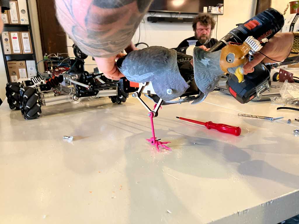
But then, we had a really great looking robot pigeon!
link to REPO
here are the design files we created for the mechanics of RUPEV