molding and casting
Topic(s) of this week
- molding and casting (video, review)
- Design appropriate objects within the limitations of your process
- Demonstrate workflows used in mold design, construction and casting
Hero shots
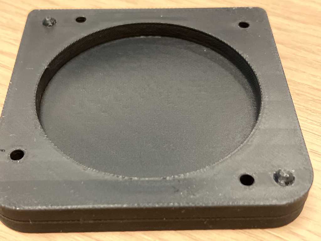
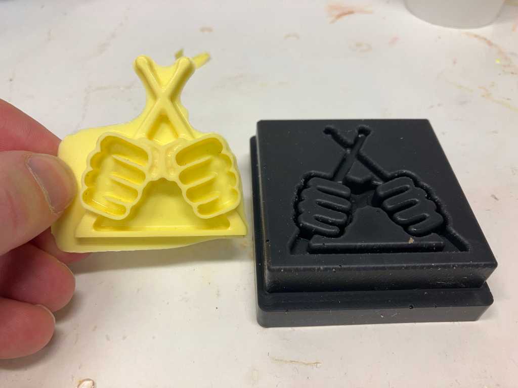
3D FDM printed mold:
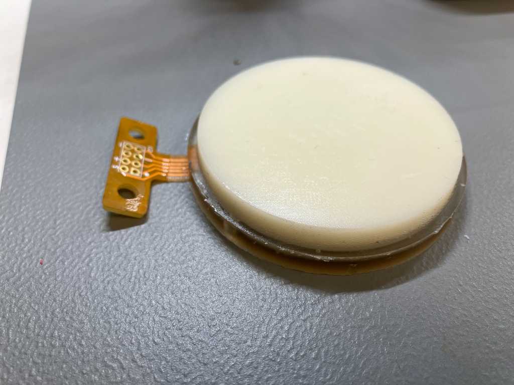
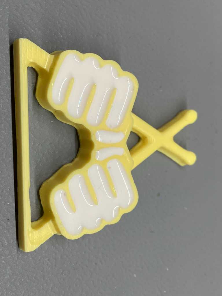
PU cast using this mold:
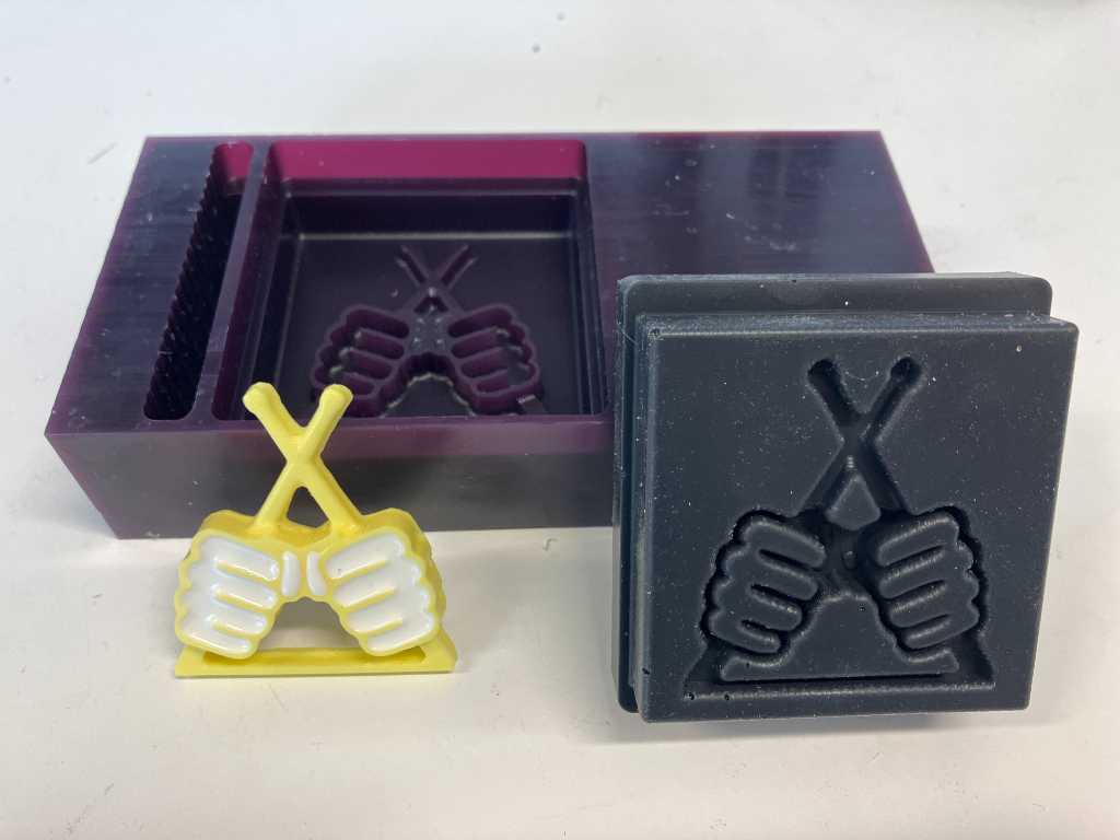
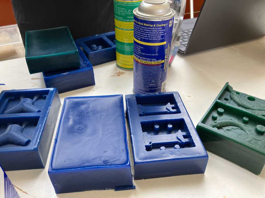
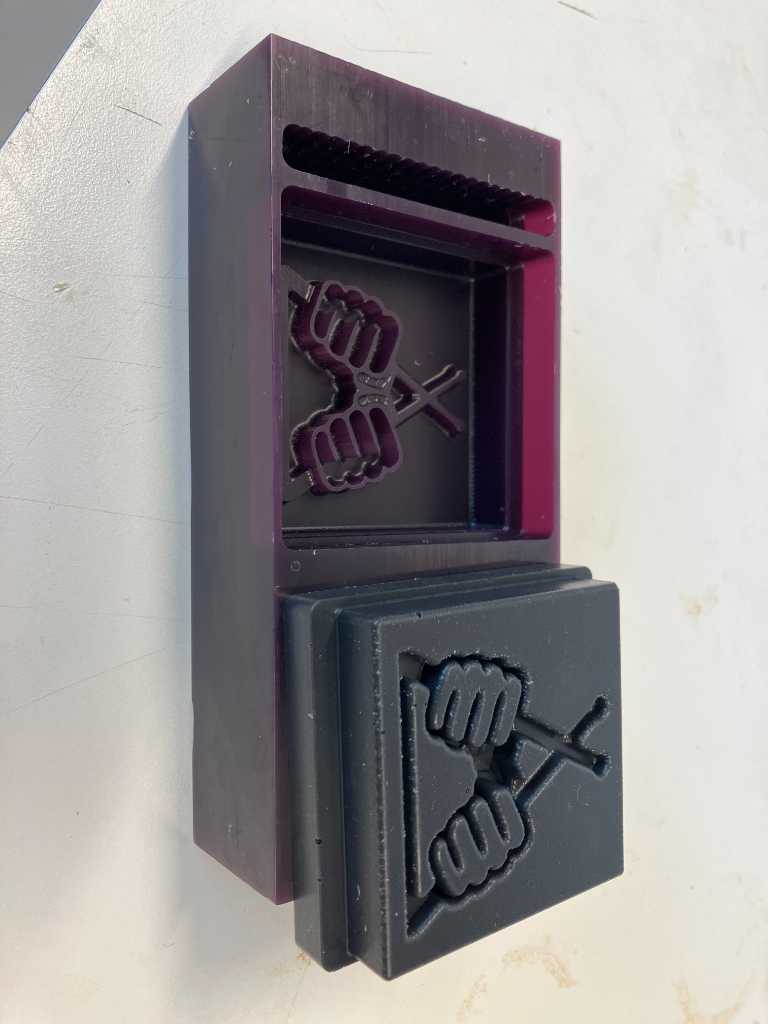
3-way mold: machine wax, silicone 40 shore, Polyyurethane
Assignments
Group assignment
- Review the safety data sheets for each of your molding and casting materials
- Make and compare test casts with each of them
- Compare printing vs milling molds
Individual assignment
- Design a mold around the process you’ll be using, produce it with a smooth surface finish, and use it to cast parts.
What I think I already know
Molding and casting was one of my main points of interests in this fabacademy course. I did just a little bit of it in the recent past and liked the process. Although I don’t like mess, I already know that it is possible to work cleanly and this should be the way to do it with these types of (mostly potentially harmful) materials.
What I want to learn
A big part of my final project will be around molding/casting. All my pressure sensors will be casted in a mold. Although this will be the same mold for every sensor, mold design, trying materials, optimizing work processes will be very relevant. Especially since my final design requires at least 19 identical pressure sensors. And if all goes well, this might increase to 76!
A lot of the molding and casting of these sensors I’ve already done in the past weeks. So for this week I can rely on what I’ve done so far.
Still, I’d like to make a 1-part mold and use that for 3-way casting: positive mold, negative mold, positive end-product.
SSTM planning
Supply
| Day | Supply | Tasks |
|---|---|---|
| Thursday | 08:00-09:30 (train) | - |
| 10:00-18:00 | group assignment | |
| 20:00-22:00 | documentation | |
| Friday | 10:00-13:00 (fablab) | FP casting |
| Saturday | 11:00-13:30 | programming FP |
| Sunday | 19:00-23:00 | Programming FP |
| Monday | 14:00-17:30 (fablab) | molding for FP |
| CNC milling 3-way mold | ||
| 19:00-00:00 | programming FP | |
| Tuesday | 9:00-17:30 (fablab) | CNC milling 1-way mold? |
| casting negative | ||
| FP casting | ||
| 20:00-23:00 | Document | |
| Wednesday | 9:00-12:00 (fablab) | casting positive? |
| FP casting | ||
| 12:00-13:00 | Local review | |
| 13:00-14:00 | Regional review | |
| 15:00-18:00 | Neil time |
Tasks
Have you answered these questions?
- Reviewed the safety data sheets for each of your molding and casting materials, then made and compared test casts with each of them
- Documented how you designed and created your 3D mold, including machine settings
- Shown how you safely made your mold and cast the parts
- Described problems and how you fixed them
- Included your design files and ‘hero shot’ of the mold and the final object
- Leave feedback in Nueval that this weekly is ready for evaluation.
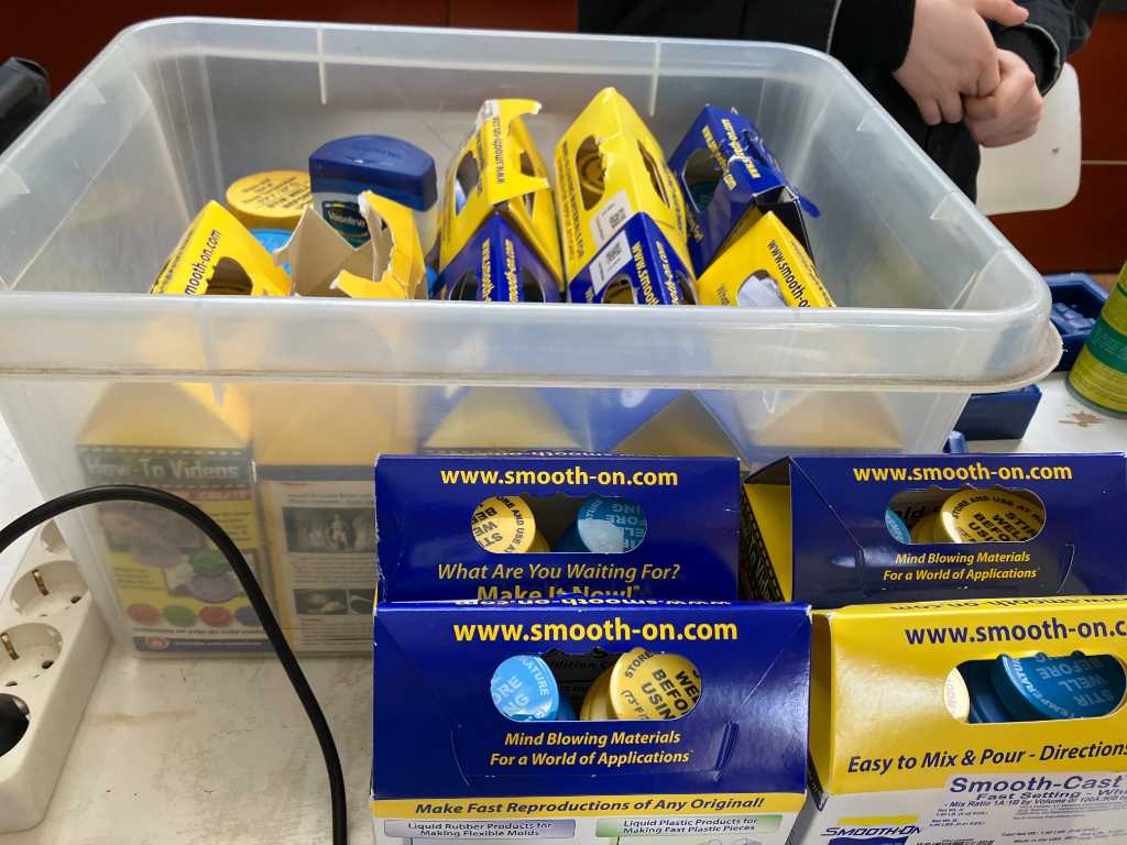
WAAG session & Group assignment
Michelle gave us a workshop on molding and casting. At WAAG there are lots of Smooth-on products available! Great stuff.
Materials that you make the mold out of and materials that you cast with should be compatible. RTFM to know this!
We’re going to use a block of machinable wax and mill a model. Next we’re going to cast a mold using this model. And finally we’re going to cast our final product in this mold.
To create a mold, you need ways to align and fix the two-part mold together (e.g. pins) and pouring/venting holes.
Different materials have different pot times. Make sure to note this! Otherwise the material is already unpourable before you get to pouring…
A good hint on mixing part A and part B: Add a bit of colorant to one part. When mixing both, you can see if you mixed properly.
Transparent products are the most toxic of all the products.
A 3 WAY mold = go positive, negative, positive. E.g. machine positive, cast mold, use mold to cast final product.
A 3 PART mold is a mold that consists of 3 parts.
If you want to use biomaterials, there’s a huge library here: materioms.org and this Fabricademy presentation.
Safety datasheets
We’re going to check these parameters:
Safety
- Room conditions work environments
- PPE Personal protection equipment
- Exothermic or endothermic
- Toxicity
- Environmental harm
- Specials or others (e.g. Storage)
Material properties
- Shelf life
- POT time
- Curing time
- Ratio mixing
- Viscosity
- Shore hardness
- shrinking
- Specials or others
We’re all going to check one product. Here’s mine:
I’m going to check OOMOO25, a Tin-cure silicone rubber that can be used to create molds by pouring over original models. Safety datasheet number 823A/823B.
Safety
- Room conditions work environments
- Room temperature
- properly ventilated area: “Room size” ventilation
- PPE Personal protection equipment
- all the usual: safety glassed, long sleeves, use gloves made of rubber, vinyl, neoprene or PCV. Not latex gloves!
- Respiratory protection is not normally required in well ventilated areas
- Wash hands after use
- do not breathe vaports or mists
- Exothermic or endothermic
- not mentioned anywhere
- Toxicity
- no data available, except Carcinogenicity: no components present at levels >= 0.1% is identified as (potential) carcinogen
- Environmental harm
- prevent spilled material from entering natural waterways, sewers, etc.
- No special environmental precautions required.
- no data available regarding toxicity, persistency, etc.
- Specials or others (e.g. Storage)
- Cool, dry, well-ventilated place away from heat and direct sunlight.
- Waist disposal: up to the user to define if it needs to be treated as hazardous waste
Material properties
- Shelf life
- not mentioned anywhere
- Pot time
- 15 minutes
- Curing time
- 75 minutes
- post curing 4 hours at 65C will eliminate residual moisture and alcohol
- Ratio mixing
- 1-to-1 by volume
- mix for 3 minutes
- Viscosity
- both parts have low viscosity for easy mixing and pouring (4250 cps when mixed)
- Shore hardness
- 25A
- shrinking
- Negligible
- Specials or others
- No vacuum required
- does not have geat tear strength
- good for making 1 or 2 piece block molds.
- Good for creating molds using casting plaster, resins and wax.
- Silicone rubber may be inhibited resulting in tackiness or lack of cure after curing time has passed. Materials that were found to cause cure inhibition include sulfur-based modeling clays and latex rubber. Apply sealing agent, barrier coat of clear acrylic lacquer.
- Release agent not required but can help.
- Pour at least 1.3cm over the highest point of the model surface.
Use VCarve Pro for 3D milling
- Set up job size (size of machinable wax block) e.g. 90mm x 140mm
- Material Z Zero on stock top (or bottom if it’s a wonky block)
- Good idea to place design a little below the top so the top is milled down first and is made even
- Make sure XY position is correct (at WAAG X-axis is the long side of the shopbot)
- Model - import component/3D model -> import OBJ file of your model
- set the initial orientation of the model and center it (center model button)
- use Zero plane position in model to position where your model is related to Z Zero
- Now you should see your model in the 3D view with the stock outlines around it
- use Material Setup to position your model more precisely. You’ll see the model with the stock outlines around it. If you don’t do this you should get this as a popup as soon as you create a toolpath
- In toolpaths use the 3D roughing toolpath and 3D finishing toolpath
- 3D roughing toolpath
- Select the mill you want to use from the tool database, e.g. SB Starter Set - End Mill (3mm) rough Wax (3.0mm pass depth, 1.8mm step over 60% (could be bigger as it is a roughing path. check time to see if it will be faster), 9000 rpm speed rate, 50 feet rate, 15 plunge rate)
- Machine limit boundary: use material boundary if you want to mill away all of the material. otherwise use model boundary. Check the preview to know if it does what you want!
- machining allowance: around 0.5mm (which will be left over for the finishing toolpath)
- Roughing strategy: Z Level -> Raster Y (is easier on the machine is it only moves the spindle on the bridge instead of moving the entire bridge). You can also use 3D raster but that takes much longer
- 3D Finishing toolpath
- Select the tool again. e.g. End mill (3mm) finish: stepover 0.3mm 10%, spindle speed 9000 rpm, feed rate 50.0 mm/s, plunge rate 15.0 mm/s. So only the stepover is changed a lot.
- Set the area machine strategy to raster. Test if offset makes sense (depends on model). You might need a 2nd finishing toolpath and set the angle to 90 degrees.
- 3D roughing toolpath
- Click calculate all a lot of times!
Fixate the block of machining tape with doublesided tape and wooden jig around it.
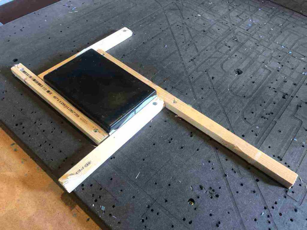
from documentation of Michelle
Do not turn on the ventilation so you can reuse the wax. Vacuum the table before you use wax!
Make and compare test casts
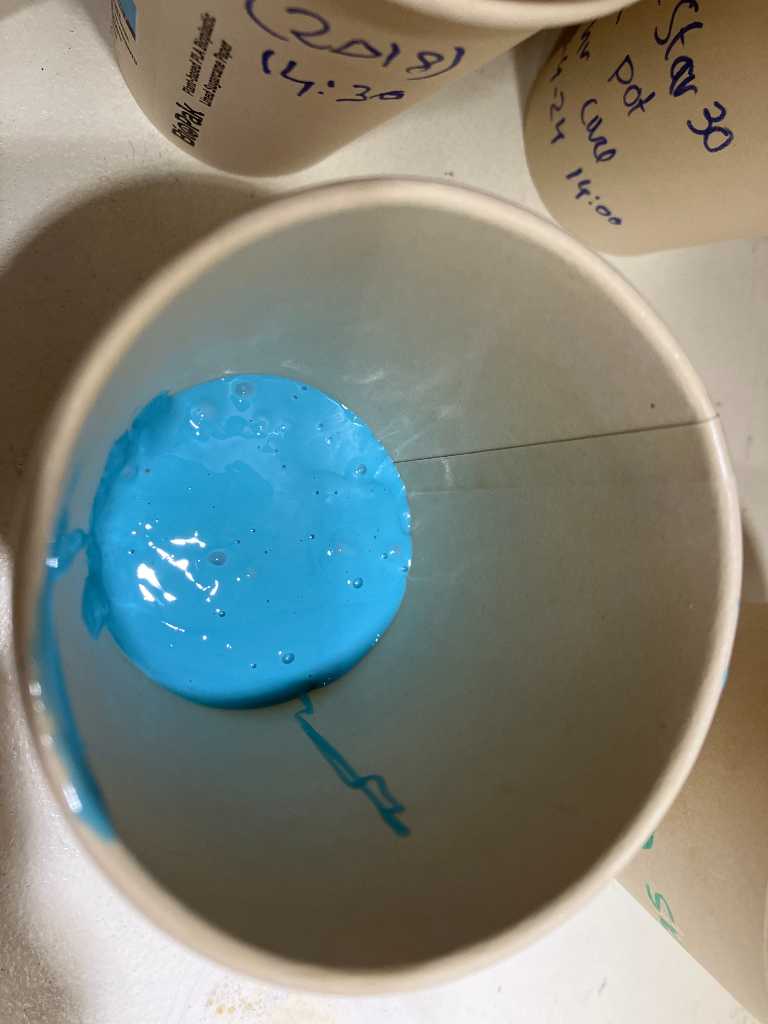
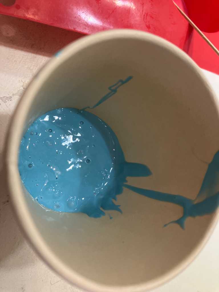
A test cast can be done in a paper cup. It is not needed to create a mold first. Don’t do too much!
Edwin is pouring Mold star 30
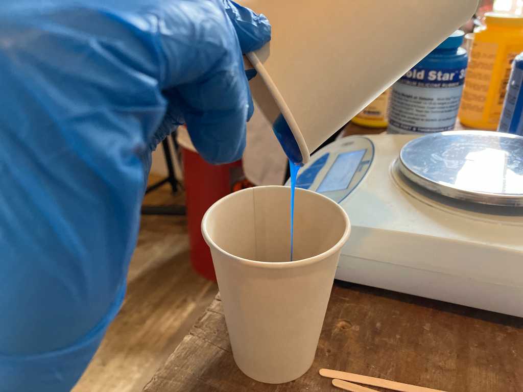
Joe is pouring Dragon skin 10NV

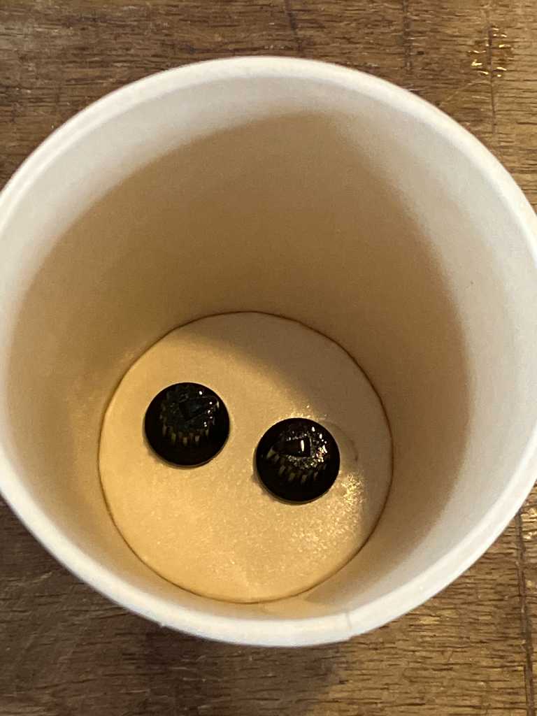
I’m making a mold of 2 knobs using OOMOO 25
Lots of bubbles and hard to pour. Strange because it is a new packaging. I tried stirring part A and part B in the can. Especially part A was very hard to stir. Michelle is going to call the shop. Most probably it’s just not good…
After 75 minutes it’s time to open the “mold”:
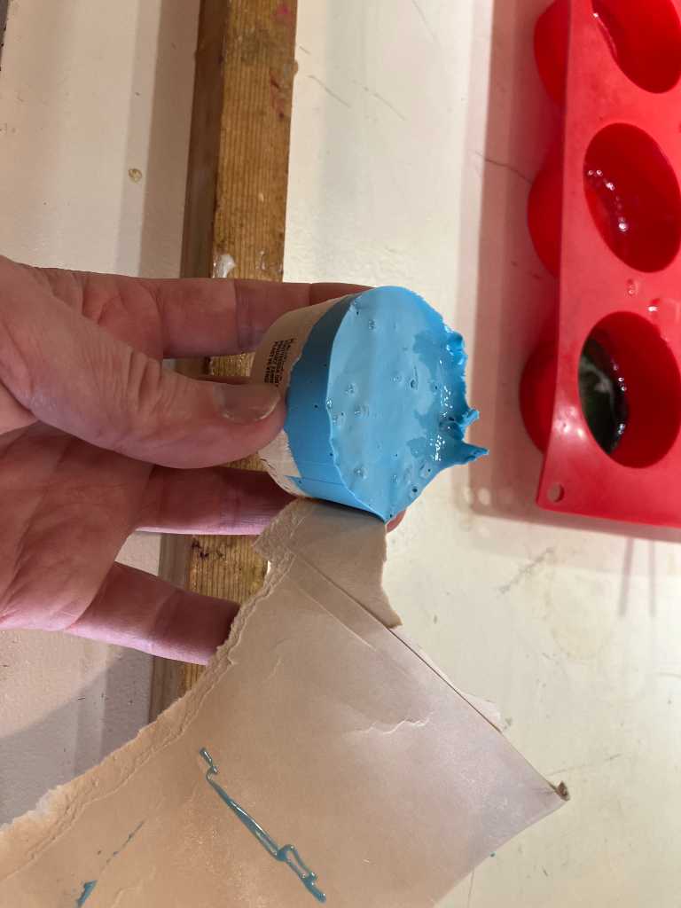
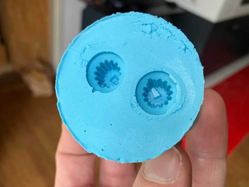
That actually looks fine. Even though the silicone was very hard to pour (we got feedback from the shop that it was actually not good and we get refunded). Just a couple of bubbles in the areas of interest. It came of the knobs very good:
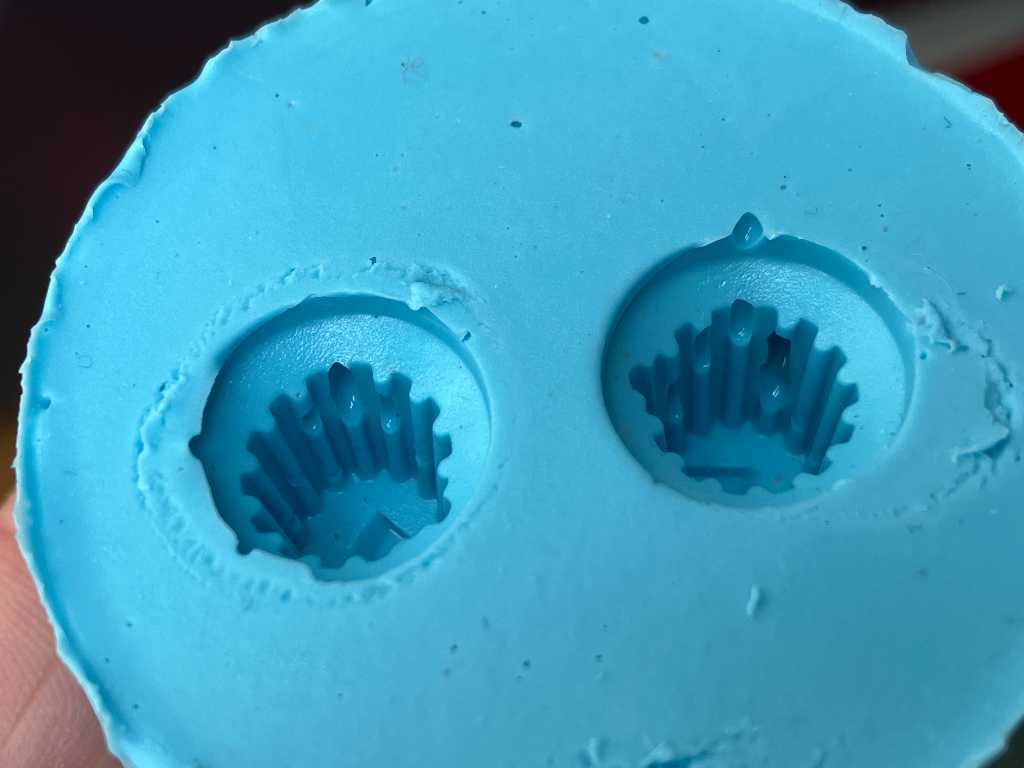
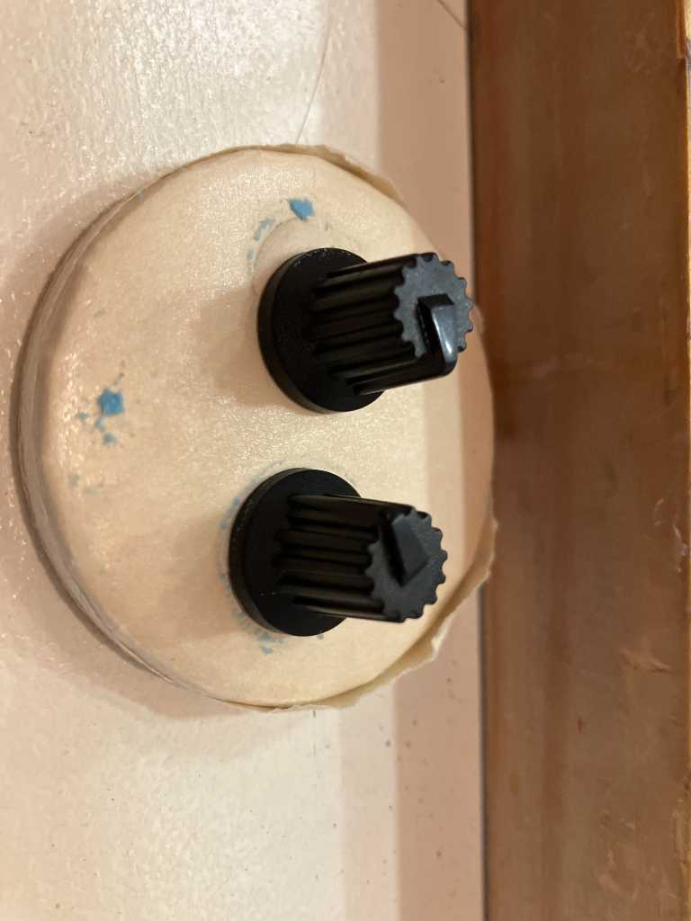
It’s just still too sticky. That should be the case after 75 minutes. Again, due to faulty silicone…
REALLY STICKY!
So this concluded our group project. Fun times!
Individual assignment
3 way mold
I’ve done lost of casting over the last couple of week because my final project requires it. Nevertheless, I wanted to do a 3-way mold this week. Meaning a positive mold, casting the negative silicone mold out of that and finally casting a positive “final” product using the silicon mold. We have a Roland MDX-50 in our Fablab which I haven’t used yet. So lets go!
Design a mold
I quickly designed a mold using my personal drum logo. I know my time is limited this week so it’s going to be a 1 part mold.
I have my logo in SVG format. So I import this into a Fusion sketch and create something out of this.
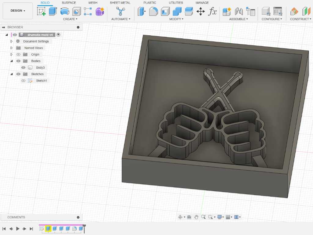
Nothing too fancy. And as this is a 1 part mold, I don’t need keys, vent holes or pouring holes.
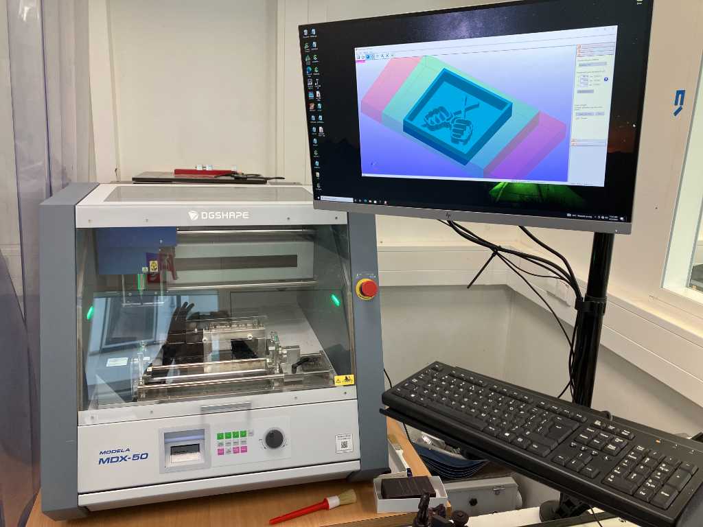
Roland modela MDX-50
This is our Roland MDX-50. We always have the rotary unit attached. But you can mill without using the 4th axis. The toolpaths are created using proprietary software called SRP player. Controlling the machine itself (i.e. sending the gcode to it) is done using another proprietary software called VPanel.
To turn the machine on, use the power/emergency button on the right hand side.
Next press enter to start homing.
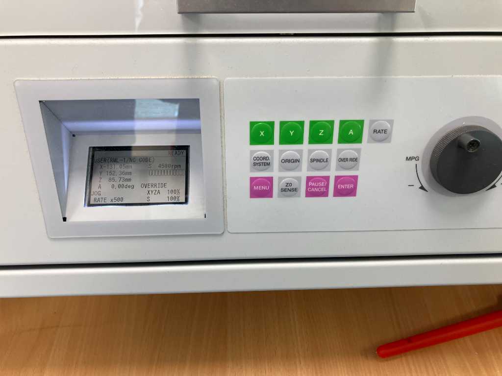
The three green buttons select an axis. Pressing one of these buttons and turning the dial will move that axis.
X = left to right
Y = front to back
Z = bottom to top
A = rotation axis over the X axis
The machine has several coordination systems available. This doesn’t make things easier… The Machine coordination system is fixed, factory set system. Meaning you can’t set zero’s in this sytem. All the other coordination systems do allow you to null it.
In our fablab, we have the protocol to ALWAYS use the “User” coordination system. The others are set properly, so we don’t want people to mess this up.
Press “coord system” button to change coordination system.
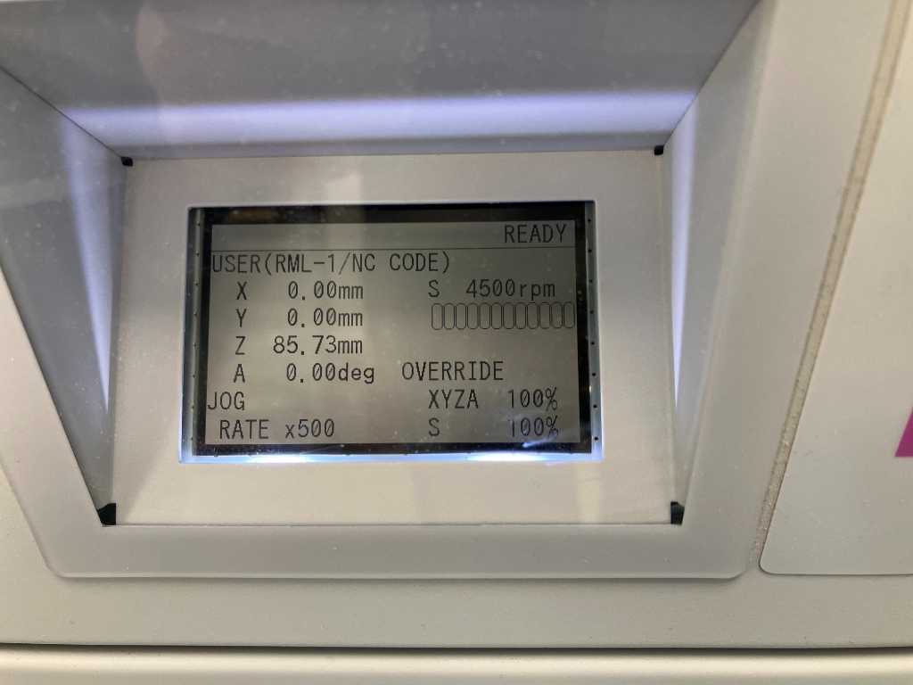
Setting the zero position is done as follows:
- Make sure you’re in user coordination system.
- Select an axis
- Use the rotary knob to go to the zero position
- Long press the Origin button to set zero for the selected axis.
As we have the rotary unit installed, the Y and Z zeros are not negotiable. The Y zero should be exactly the center of the rotary unit. The Z zero should be exactly the center of the rotational axis.
Usually you don’t change this, but it is good to check if the current zero’s are set properly.
The machine has some preset locations. Use Menu -> move menu to select them and press enter to let the machine go to that location. To check Y axis zero, go to the G59-XY position. The Y position is the correct Y zero (we’ve set it up like that). Again, always work in the User coordinate system and don’t change anything in any other coordination system!
The X zero is interesting. It should be set to about 3 cm (hard to measure, but we believe it is something like 27mm) to the RIGHT of the rightmost edge of where you want your model to go. This is due to the rotational unit. And cannot be set differently…
If you don’t use rotational milling (but again, we always do), the Z zero can be either stock top or stock bottom. X and Y zero is in center of your model.
The Roland MDX-50 has an automatic toolchanger with 6 positions. If you want to change a tool manually, press menu 2x to enter tool change menu. Select the tool position and click enter. The machine will automatically measure the tool length.
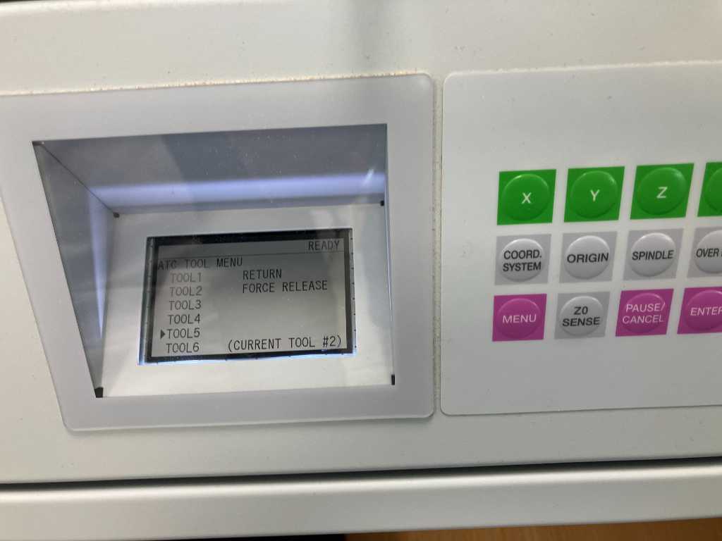
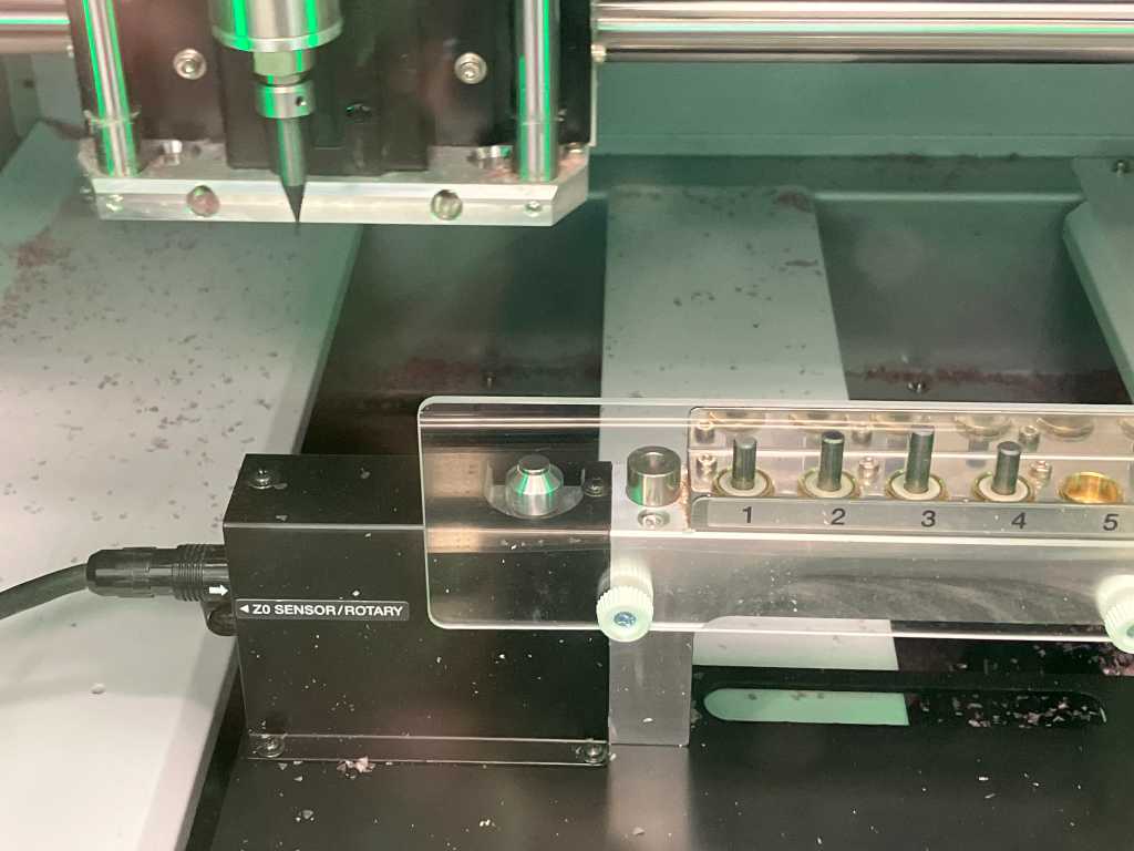
The tool measurement sensor is to the left of the tool holders.
Machinable wax
We only use our Roland MDX-50 with machinable wax. This is so we can collect the chips and remainders as cleanly and unpolluted as possible. Because we’re casting this into new blocks again. The machinable wax we use is this:
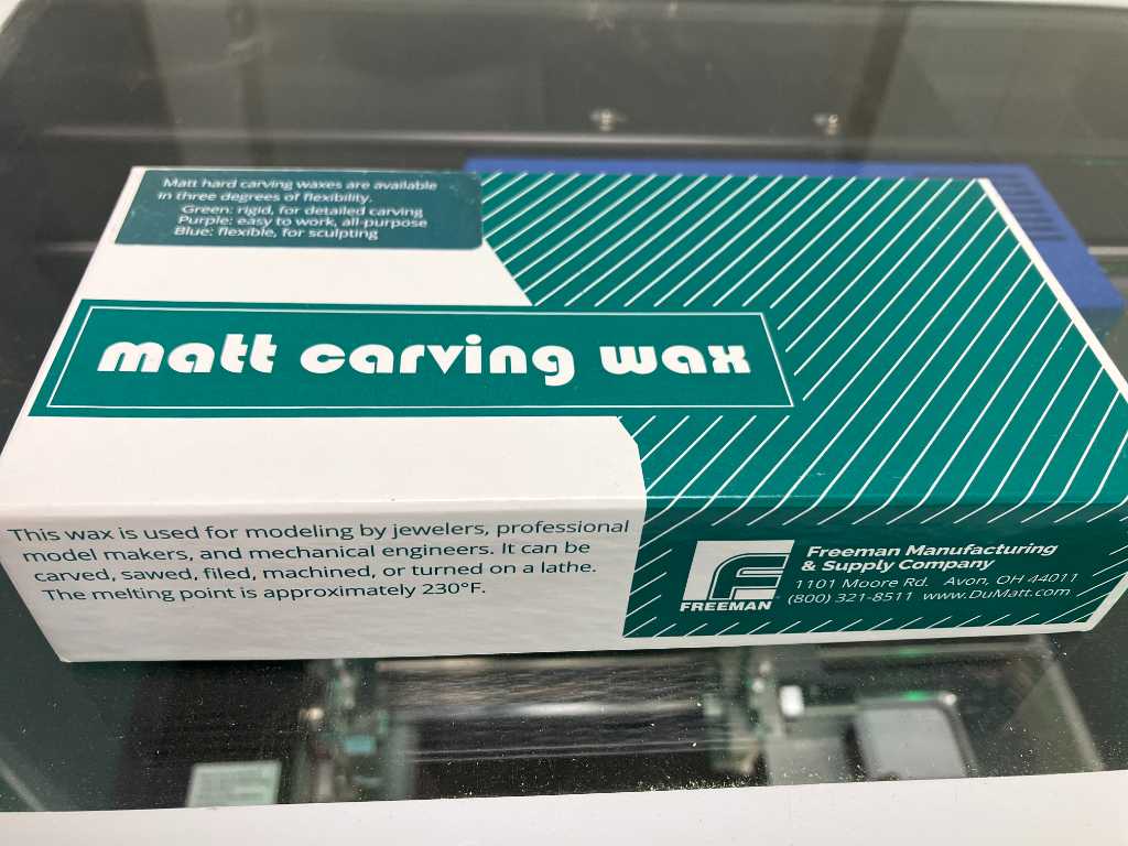
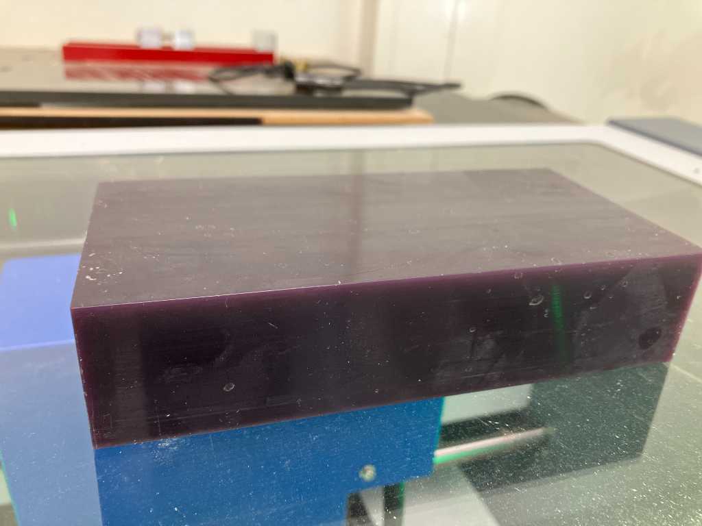
Dimensions of one block is 165x80x37mm.
SRP player
SRP player is the proprietary software tool to create toolpaths for this machine.
Open the STL in this software. On the right hand side there are a few tabs that you need to go through to set up the stock and create toolpaths.
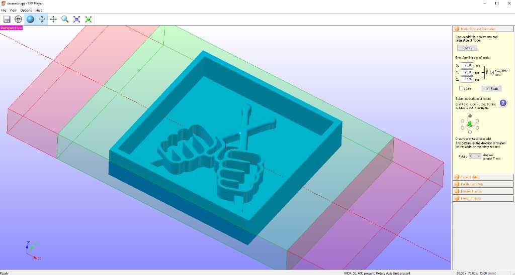
1. Model size and orientation
Check the dimensions of the STL, select the orientation of the model
2. Type of milling
Select if you want a faster milling time or a smoother surface.
Select if your model has many flat areas or many curved surfaces.
select Cylindrical workpiece if you want to do rotational milling. You can offset the model wrt to the rotaional axis by using the Eccentricity button.
Select Block workpiece if you don’t want to do rotational milling. Select if you want to mill from top side only, or if you want to mill both top and bottom side.
Use support when needed, especially with rotational milling!
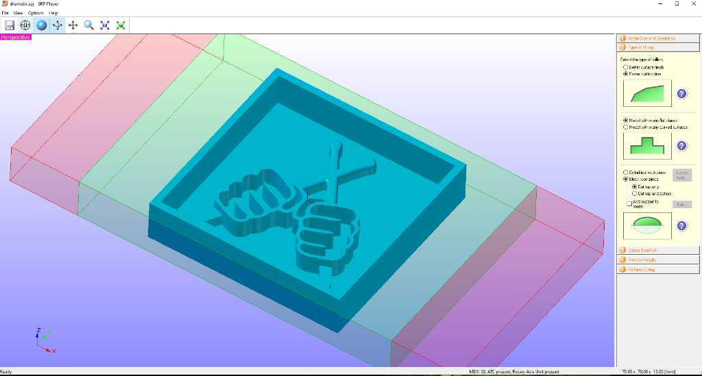
Now you see your model in blue, with the usable part of your stock in green and the stock that is clamped in the rotational unit in red.
The model is always placed in centerX/centerY/centerZ. And there’s nothing you can do about this. Only trick is to change the X length of the stock to let the machine think that you have less stock than you actually have. That way you can be more preservative of your stock. With the rotary unit attached, you cannot mill for example from stock top.
3. Create toolpath
Set the stock material and stock size. Dimensions of one block is 165x80x37mm (don’t pay attention to the values in this image).
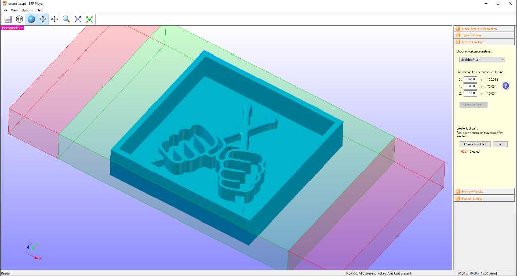
Next click create tool path button.
And then click edit to set up this tool path (and tools).
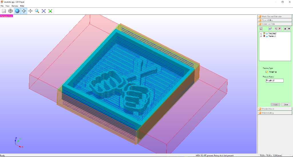
There are 2 toolpaths filled in automatically. A roughing and a finishing pass. Click the little plus icon to see it’s content and change it accordingly:
- Top surface: set to the top of you only want to mill from that side. Create a second tool path with this set to bottom to be able to mill both sides.
- Cut area: use all to mill all stock away except your model. Use partial to limit this and keep stock intact. This is preferred.
- Depth: similar to cut area. Usually keep this to all. But again, depends on your model.
- Tool: select the tool you want to use for this toolpath.
- Contour lines: use Up Cut.
- Cutting parameters: feeds and speeds. Are predefined. Note: The spindle max rpm is 15k rpm.
Do the same setup with the finishing tool path and click create tool path again.
For my model I used 2 roughing passes(1x 6mm end mill and 1x 3mm long flute ballnose mill)and 1 finishing pass (3mm long flute ball nose mill). For all tools I used the pre-defined feeds&speeds.
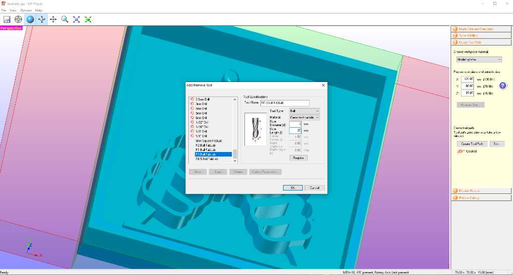
Add tools
If you need to add tools because the tool you want is not in the tool list go to Options - Add/Remove Tool:
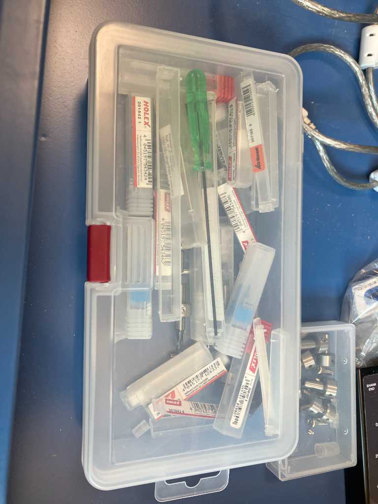
Tools that we have available for this machine.
4. Preview results
SRP player has a very limited toolpath preview. You’ll only see the expected end-result.
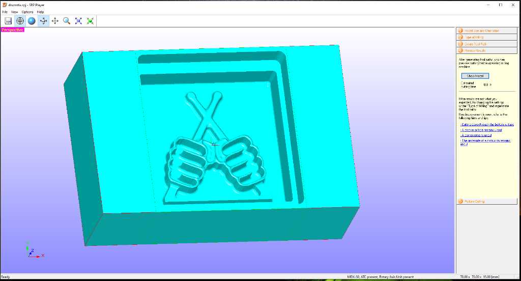
SRP player cannot indicate if the collet crashed into your stock! Pay attention! It does not know the dimensions of your collet!
5. Export to the machine
Use the perform cutting tab to export the toolpaths to a file that VPanel can read.
First check the Tool list.
Make sure in edit magazine The tools are correctly and in the correct toolholder number.
Make sure “Output to file” is checked!
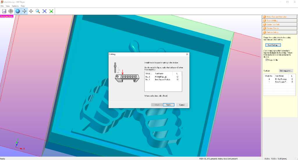
Click start cutting to output the toolpaths to a file. The machine will not start cutting though. It’ll only output a file…
You’ll be asked to make sure the correct tools are in the toolholders.
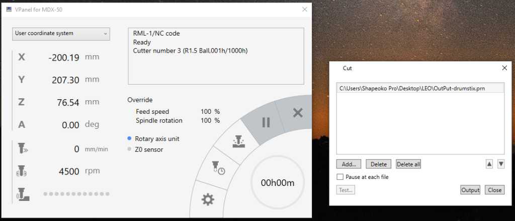
Vpanel
VPanel is the proprietary software to operate the Roland MDX-50. You can zero the machine here as well, but I find it easier to do this on the machine itself.
Make sure that in VPanel the required tools are in the correct toolholder position (cutter management icon).
Next press the middle button (cut?) and select the file you just got from SRP player.
AS SOON AS YOU CLICK OUTPUT THE MACHINE WILL START!
Checking length of the tool:
Roughing pass 1 with 6mm end mill:
Roughing pass 2 with 3mm ball nose mill:
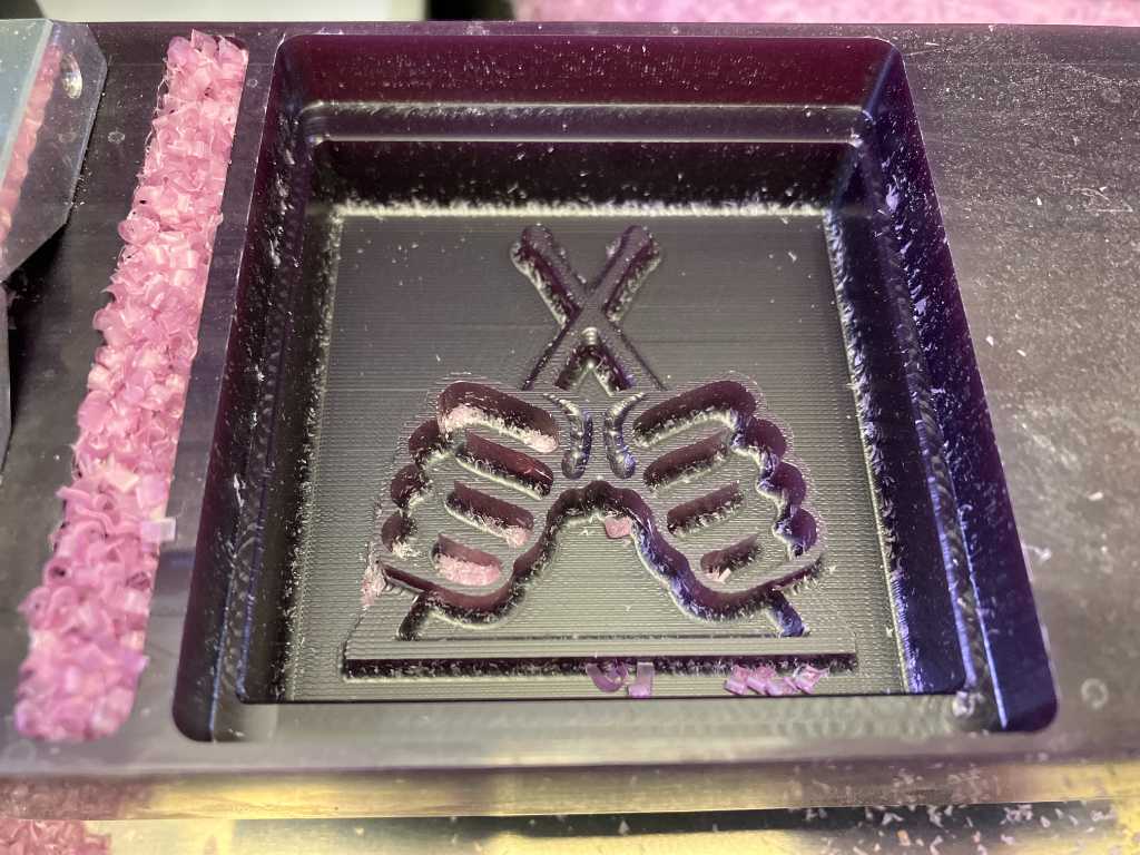
Finishing is done with a 3mm ballnose mill. You can see the ballnose in the flat surface. But we don’t have a long-flute 3mm flat endmill so this was the best I could do.
Casting silicone
I first checkt the required volume by pouring water into the mold: 100ml.
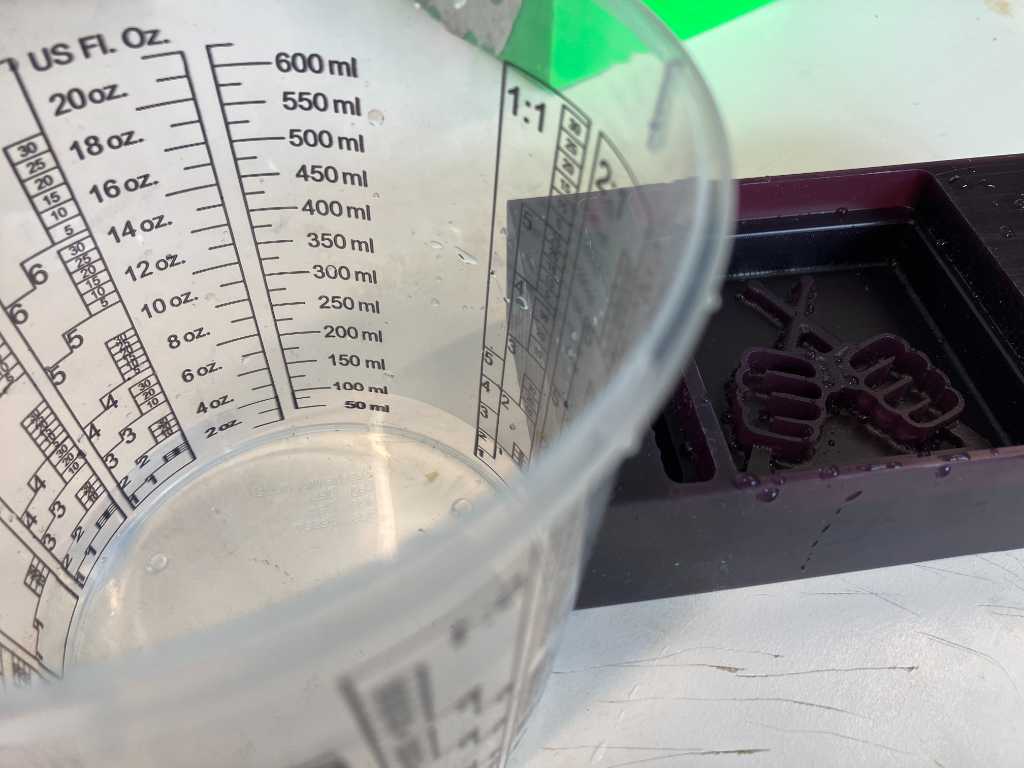
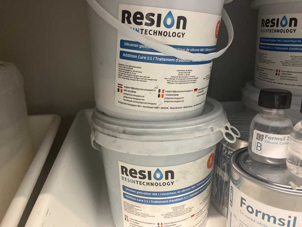
I’ll be using Resion shore 40 silicone. It is 1:1 by weight. Pot time of 10 minutes, curing time of 8 hours.
The silicone material is not really fluid, so most probably quite a bit will stick to the wall of the cup. I’m going to make 150 grams in order to get to 100 ml usable silicone.
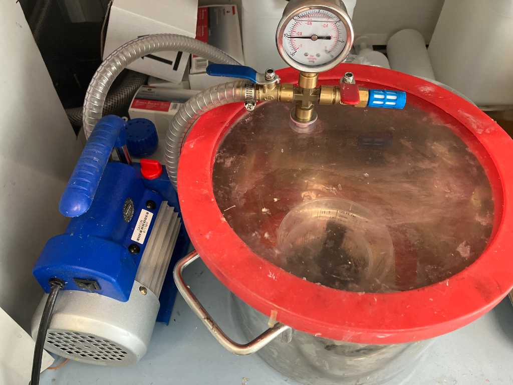
I always vacuum Polyurethane for as long as possible to remove as much bubbles as I can. So I’ll do that with silicone as well.
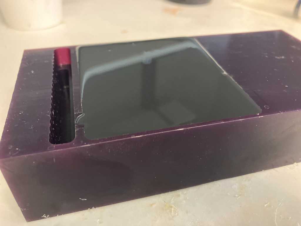
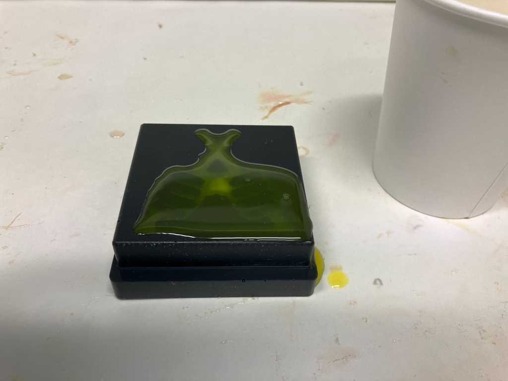
That went well. I actually used a syringe too to first fill up the “dificult” pockets of my design. After that I slowly poured the remainder in the mold.
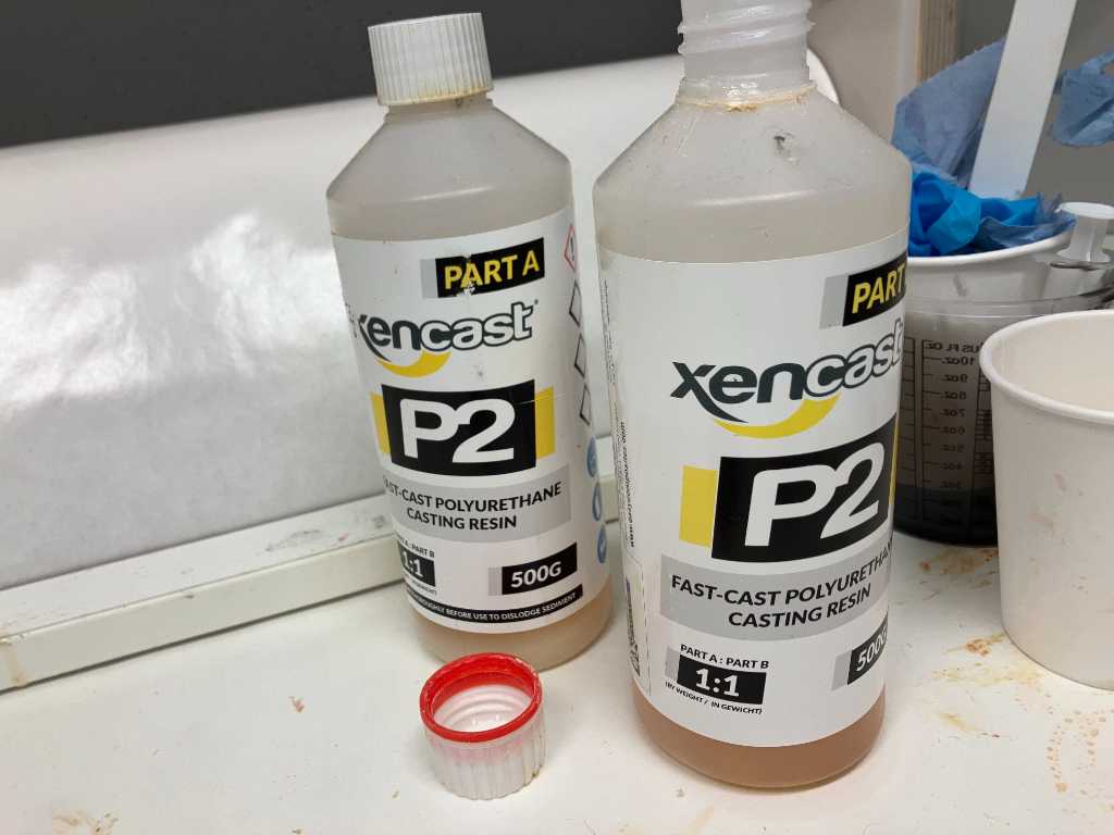
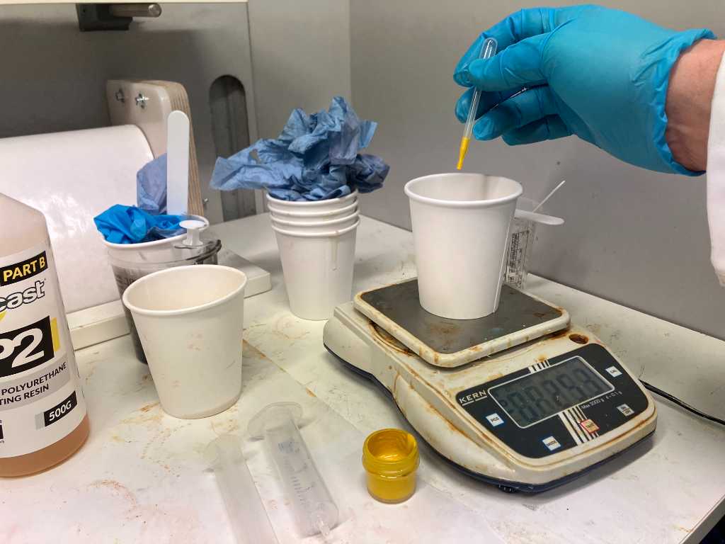
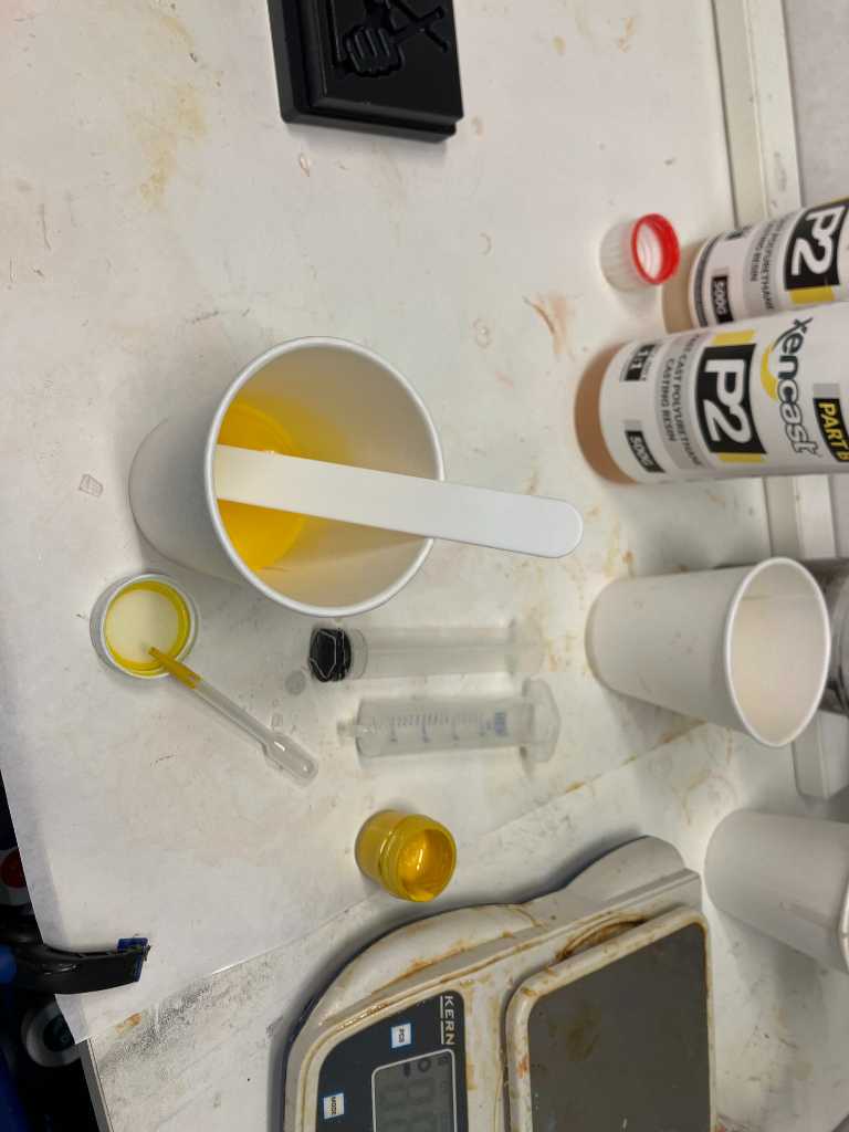
I’m going to cast with Xencast P2 polyurethane and I’m going to add a bit of yellow pigment.
2 min pot time
20 min cure time
So got to work really fast!
After 30 minutes:
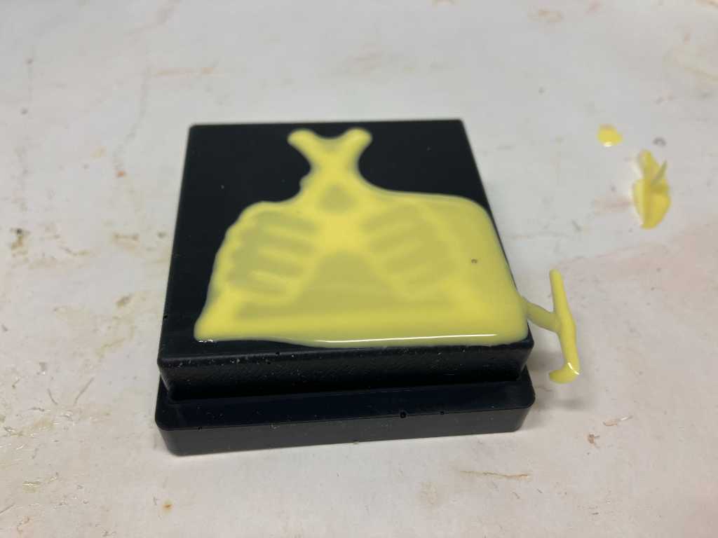
And then after some manual cleanup:
Link to repo
The design file (step) can be found in my repo.
https://gitlab.fabcloud.org/academany/fabacademy/2024/labs/waag/students/leo-kuipers/-/tree/main/files/12_molding-and-casting
Final project castings using FDM 3D printed molds
For my final project I cast a lot of top and bottom parts for my pressure sensors.
I tried a SLA printed mold and FDM printed mold.
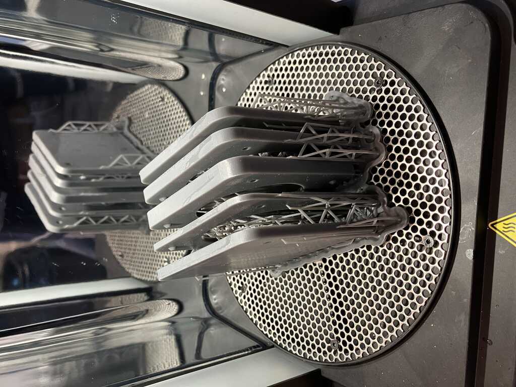
Comparison between FDM printed mold (left) and SLA printed mold (right). The left one has bit of flashing but that was easy to cut away. I didn’t make enough material for the left mold, so as you can see there are some holes. But the outcome was great on both.
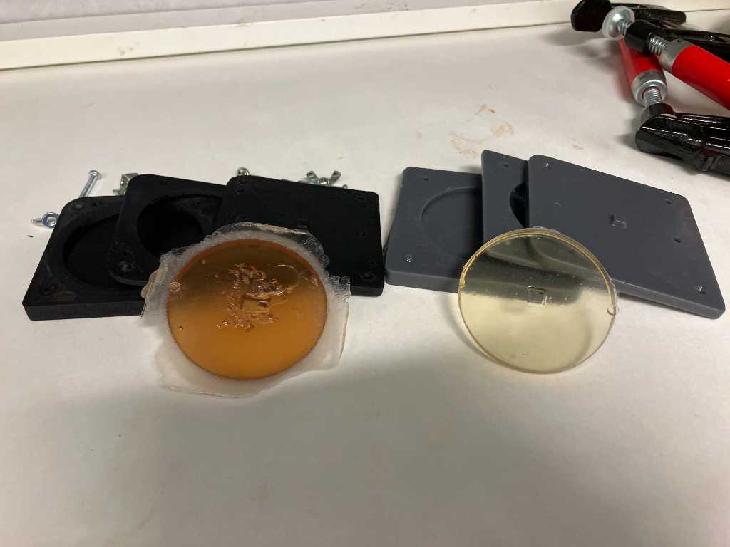
I was amazed to find out that the FDM printed mold was at least comparable in terms of smoothness! The trick is to print in highest quality and enable ironing! I think this is mainly due to the fact that my mold has a large flat surface. I don’t know if ironing will improve 3D print features when the design is more “complicated”.
FDM printing is much less hassle to make and much faster. So I went to create a lot of molds that way for my final project.
My molds are by the way printed on a Bambulabs X1C using standard black PLA.
So here are some photos. More info is in my final project documentation.
Pressure sensor idea:
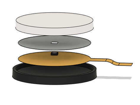
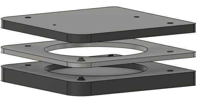
Mold to make the sensor:
Final sensor:
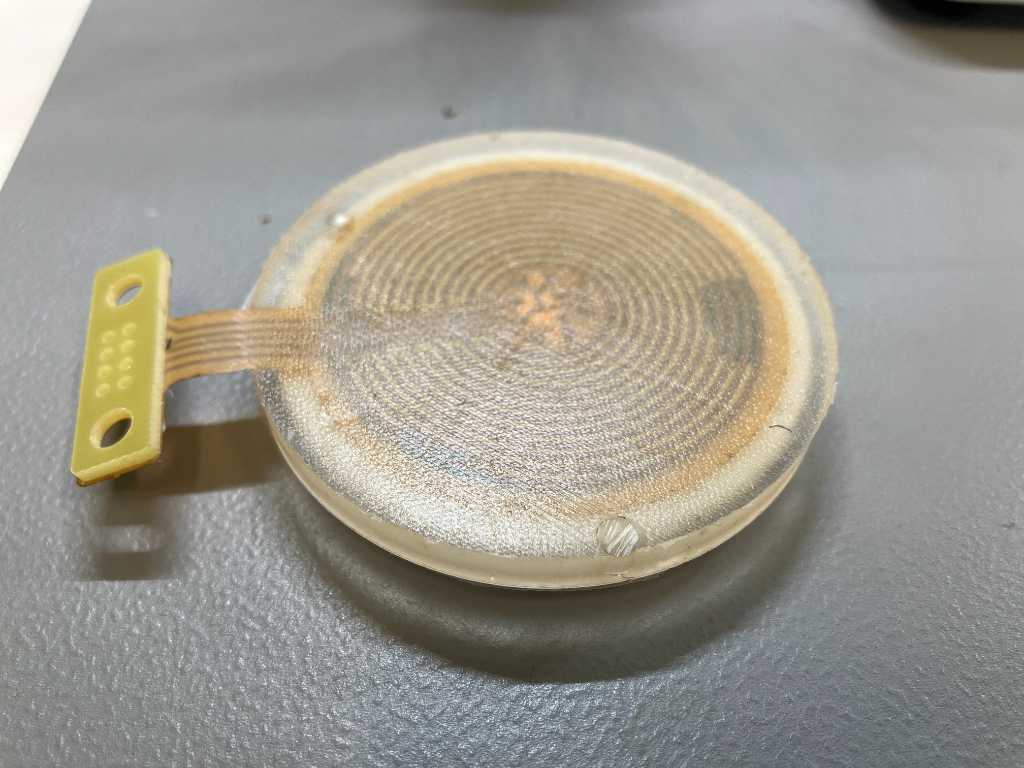
As you can see the bottom of the sensor has more texture. This is because I didn’t use ironing setting when 3D printing this mold.
Cut in half to check for bubbles inside:
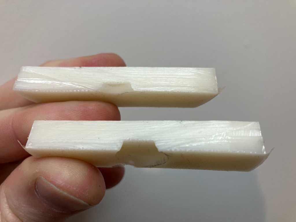
The process of creating the mold and casting is documented in my final project page regarding pressure sensor.
Link to repo
See final project repo.
What I learned this week
Successes
I continued working on the pressure sensor casts. And they come out great. Very happy about that.
Also I like that I was able to create a silicon mold out of a machined piece of machinable wax. I didn’t think I had the time to do it this week, but managed to!
Fails & Fixes
SRP player is a terrible program. It’s hard to see what’s going on, it uses a lot of screen real estate for showing unimportant parts where the actual setup (i.e. feeds & speeds) is done in a small dropdown menu, the preview is unusable because you can’t actually see what the toolpaths do, etc, etc.