embedded programming
Topic(s) of this week
- embedded programming (video, review)
- Implement programming protocols.
Hero shots
Assignments
Group assignment
- Browse through the datasheet for your microcontroller
- Compare the performance and development workflows for other architectures
- Document your work to the group work page and reflect on your individual page what you learned
Individual assignment
- Write a program for a microcontroller development board to interact (with local input &/or output devices) and communicate (with remote wired or wireless devices)
What I think I already know
I learned to program microcontrollers during my study and my first job (PIC16F877/PIC18F2620 anyone?) and back then did quite some DIY stuff with it. I lost interest because it was too much hassle to get it onto a PCB and PCB manufacturing wasn’t that straightforward back then (pre-arduino time…). Until I started working at our Fablab, I didn’t really do any mentionable projects with it. However, I did program in all kind of languages, so I’m no stranger to that.
What I want to learn
I’d be interested to learn about one of the “new” languages: Go and/or Rust. Also I look forward to using a microcontroller family that I haven’t used up until now. I know a bit about AVR, ESP32 and RP2040. So would like to use a SAM-D this week. I also want to try to make a proof of concept for my final project using a Velostat based pressure sensor and a WS2812B RGB LED.
SSTM planning
Supply
| Day | Supply | Tasks |
|---|---|---|
| Thursday | 08:00-09:30 (train) | learn about SAM-D family |
| 10:00-18:00 | group assignment | |
| 20:00-22:00 (train) | schematic SAM-D test PCB | |
| Friday | 9:00-13:00 (fablab) | board layout, milling, soldering SAM-D PCB |
| evening | program bootloader, program SAM-D in Arduino IDE | |
| Saturday | 12:00-14:00 | Try more SAM-D programming, focus on final project peripherals |
| Sunday | 21:00-22:00 | Document |
| Try pressure sensor | ||
| Monday | 9:00-17:30 (fablab) | search for better carbon piezoresistive sensor material -> do we have carbon conductive ink? |
| I2C communication (maybe PIO?) | ||
| see https://www.digikey.nl/en/maker/projects/raspberry-pi-pico-and-rp2040-cc-part-3-how-to-use-pio/123ff7700bc547c79a504858c1bd8110 | ||
| Tuesday | 9:00-17:30 (fablab) | I2C communication with Arduino Uno and SAMD |
| final project -cnc mill mechanical design test | ||
| documentation | ||
| Wednesday | 9:00-12:00 (fablab) | final project -cnc mill mechanical design test documentation |
| 12:00-13:00 | Local review | |
| 13:00-14:00 | Regional review | |
| 15:00-18:00 | Neil time |
Tasks
Have you answered these questions?
- Programmed your board to interact and communicate
- Described the programming process(es) you used
- Included your source code
- Included ‘hero shot(s)’
- Leave feedback in Nueval that this weekly is ready for evaluation.
WAAG session / Group assignment
Erwin gave us a workshop on embedded programming.
Arduino uses C (or C++). There’s also Micropython (and circuitpython as extension of micropython). New kids on the block: Go (made by Google) and Rust (made by Mozilla).
You can also use a real-time operating system. For example ESP32 is dual core microcontroller. Out of the box, FreeRTOS is used to run Wifi and Bluetooth on core 0. The new kid on the block of RTOS is Zephyr. Hardware abstraction is a big plus for Zephyr. It allows for easily porting code from one to another microcontroller family.
There is more than just Arduino as an IDE:
- Visual Studio Code, preferably with PlatformIO and GIT
- Eclipse
- Atmel Studio
PlatformIO is a platform that combines all required tools, toolchains, etc. required for programming microcontrollers.
Flash -> store program
SRAM -> temporarily store variables -> usually less than flash, so preferably use flash memory to store strings. Use PROGMEM to keep strings in flash memory.
Limit the amount of global variables:
If an interrupt is called, all global variables are stored in a different memory, and transferred back again after the interrupt is handled. So that takes time.
Global variables are like post-its on your fridge (nice comparison Edwin!) -> everybody can access and change them.
A good way to setting and clearing register bits:
<register> |= 0x49 (0b01000000) // setting a single bit
<register> |= _BW(6) (0b01000000) // setting a single bit

<register> &= 0xBF (0b10111111) // clearing a single bit
<register> &= ~_BW(6) (0b01000000) // clearing a single bit
Erwin showed the datasheet of the Atmel ATmega329P and explained the global layout of these types of datasheets. The datasheet lists all the different bits that can be set and explains what they do. These bits are combined into registers. These are given meaningful names, which are also explained.
Next Henk gave us a workshop on debugging embedded code and the basics of a microcontroller: bitflipping.
this design explains bitflipping to create a calculator: a cnc milled calculator based on the digicomp II made by Evil Made Scientist. See digi-comp.com
The Quentorres board that we made during electronic production week can be used as in-circuit debugger for other microcontrollers using the Arduino IDE. To be able to use this, some things will have to be installed.
Workflows
Go, Rust and Micropython are shown by Henk. Documentation was made during instructor bootcamp in Leon.
We’re all going to use the Quentorres with Xiao-RP2040.
Edwin tried microPython using Thonny.
Joanny and Vera tried micropython using Visual code.
Joe tried Arduino using Arduino IDE.
Leo tried Go using Visual Code.
Go
To use Go, you need to install Go and install TinyGo.
Once these are installed you make a directory for your project. Go commands are triggered by the command go. E.g. go mod init blinky installs the blink library. Go files have the extension .go.
Next you create a projectfile, again ending with .go and program whatever needs to be programmed. Next you compile (build) the file using tinygo build. Make sure to include the correct target microcontroller platform. And next you flash it to the target microcontroller using tinygo flash.
You can only flash a RP2040 if it is set into USB mode. To get it into this mode you need to press&hold the boot button (labeled b) and plug it into the USB port.
Go using VSCode on Windows
I want to use the tinyGo plugin in VSCode. Installing tinyGo is well documented on https://tinygo.org/getting-started/. I installed it on my Windows machine using the manual installation.
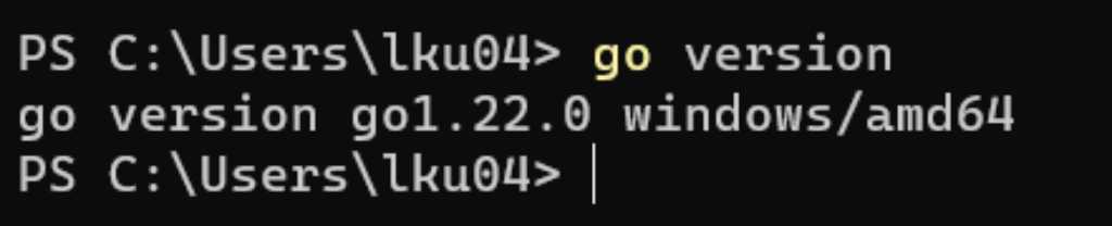
First I installed Go for Windows. And checked in the powershell if it works correctly:
Next I downloaded the latest tinyGo package from the github page and unzipped it in C:\tinyGo.
I also added C:\tinygo\bin to my PATH.
Finally I checked if tinyGo was working too:
tinygo version

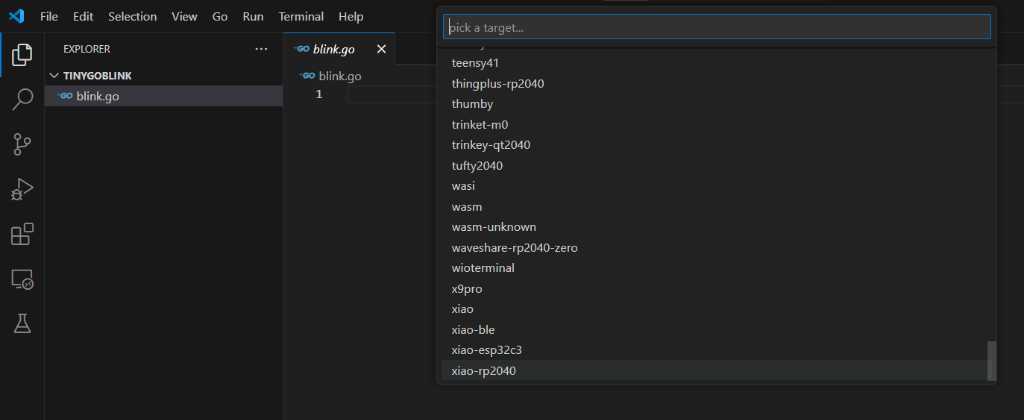
Next I installed the tinyGo extension in VSCode:
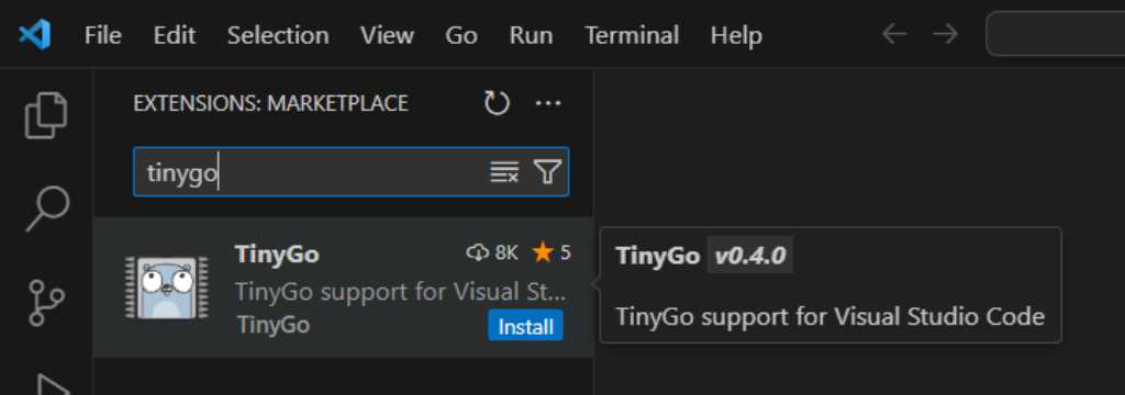
From the manual of the tinyGo extension:
To use it, click on the TinyGo status bar element at the bottom of the screen and select a target. Alternatively, you could open the command palette and search for TinyGo target.
Notes:
- It is probably necessary to reload the window once you’ve set a new TinyGo target. You will be prompted for this if it’s necessary.
- If the Go extension asks you to rebuild tools because the
GOROOTchanged, don’t do that. It will result in errors and not do what you expect. This is something that should be improved in a future version.
This extension depends on the following:
- The Go extension for VS Code. This extension should be automatically installed as a dependency.
- The TinyGo compiler, version 0.15 or later. See installation instructions for your operating system.
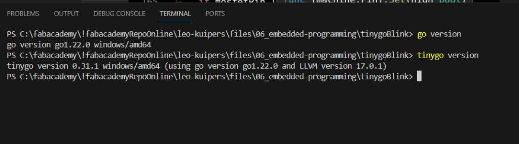
Just checking if go and tinygo are available in the SVCode terminal:
I created a folder and a file blink.go in that folder. I also ran the command go mod init blinky in the folder using the windows terminal.

This succesfully created the go.mod file which contains:
module blinky
go 1.22.0
I selected the xiao-rp2040:
And in the terminal tab I compiled my blink file using tinygo build -target=xiao-rp2040.
Next was to flash it to my Quentorres/Xiao-RP2040, by holding boot button, connecting via USB and giving the command tinygo flash -target=xiao-rp2040 in the VSCode terminal tab.
And it works!
After being able to do this once, I wanted to blink the other Quentorres LEDs. I got an error:
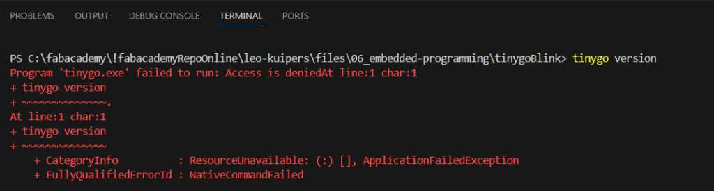
Googled this error and got https://stackoverflow.com/questions/65639505/program-tempcoderunnerfile-exe-failed-to-run-access-is-deniedat-line1-char1 where it says It is due to the antivirus running in your pc as it deletes the .exe files considering as a virus. Turn off the real time scanning of your antivirus and try executing the program.
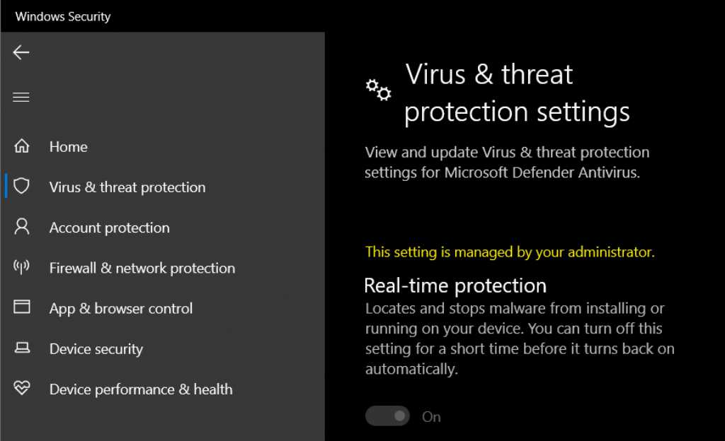
So this is Windows Defender Antivirus… But as my laptop is managed by my University’s IT, I can’t change the real-time scanning setting:
Pinouts of different microcontrollers for tinyGO are listed here.
There are some tinyGo libraries. see here. But support is not at all at the level of C or micropython.
Xiao RP2040 has a neopixel on pin 12.
Rust
For installing Rust Henk pointed us to [this tutorial](https://tutoduino.fr/en/tutorials/programing-in-rust-the-xiao-rp2040-board/. Only thing is that you should use this git repo https://github.com/rp-rs/rp-hal-boards in stead of https://github.com/rp-rs/rp-hal
For Rust you use cargo to compile and flash.
Micropython using VSCode
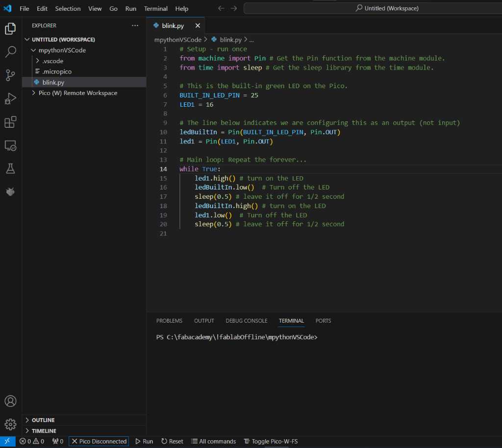
Running Micropython on the Xiao-RP2040 using SVCode can be done too.
On VS-Code install the micropico extension.
Connect the Xiao and click Disconnect to connect. Next press run and it’s blinking :-)
Arduino in VSCode
If you use platform.io in VSCode, you can start your code with #include <Arduino.h> and then use the Arduino library in your code. Things like Serial.write, analogRead, pin names, etc.
Conclusion
Nice to see Go and Rust to work. Both Henk and Erwin mentioned that library support on these two languages are not that great yet. So cool to use this for this week, but most probably not something you’d want to use for your final project.
Arduino IDE just works. As expected.
RP2040 in VScode is aweful. I had that experience 2 years ago and it hasn’t changed. Getting it into REPL mode sometimes just doesn’t work. And generally I find it very confusing that the RP2040 has it’s own filesystem, so you can run your code from your computer on your RP2040 or on the RP2040 directly. You can also edit code on the RP2040 directly. And lose all previous versions because you forgot you weren’t editing on your computer, but on the RP2040 directly. Pfff…
Individual assignment
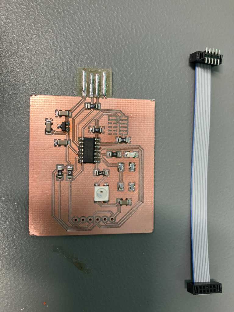
Henk gave me a SAM-D11C14A to play with. I want to see if I can connect my pressure sensor and a WS2812B LED to it. And then based on the pressure sensor the LED should get a certain color. If possible I want to extend this so that the pressure sensor level is send using I2C to another SAM-D11C14A.
Bootloader programming
Programming the SAMD will be done using the Quentorres programmer. I can also use that as an in circuit debugger as shown in this video. I used Kicad (for the first time to actually create my own PCB from scratch!) to design the SAMD PCB. That went pretty quickly and smoothly. I used the documention of Quentin Bolsee’s SAMD11C Devkit and the documentation of Adrian Torres.
Installing free_dap_rp2040.uf2 from Quentorres repo first to make the Quentorres a programmer. Next installing Fab Sam core for Arduino on Arduino IDE:
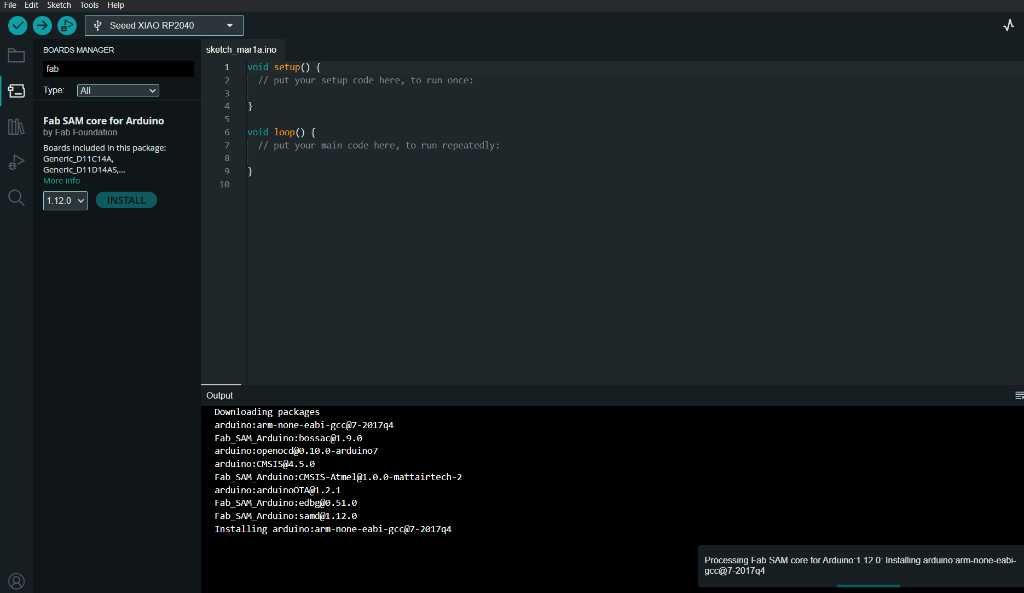
Note: Arduino IDE preferences Additional Boards Manager URLs should contain:
https://raw.githubusercontent.com/qbolsee/ArduinoCore-fab-sam/master/json/package_Fab_SAM_index.json
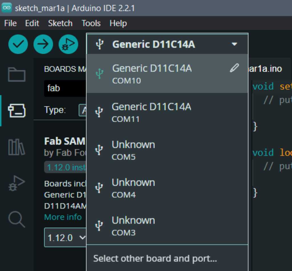
And select the SAM-D11C14A and the correct COM port:
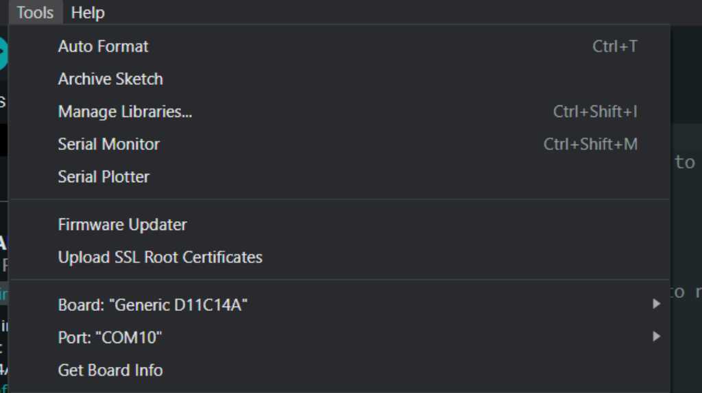
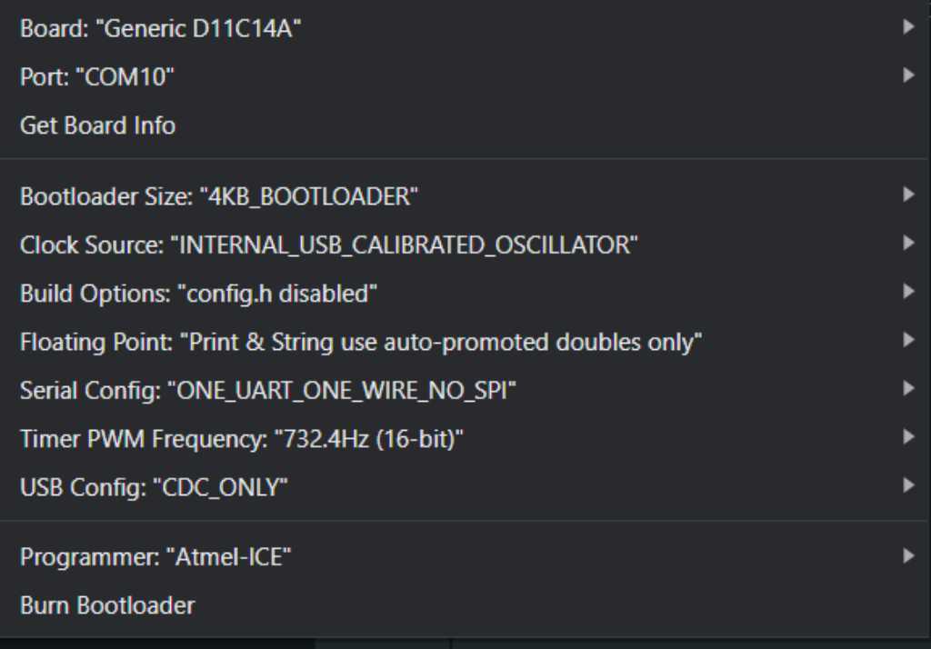
programmer should be set to atmel-ICE.
Next press Burn Bootloader and hope it works:
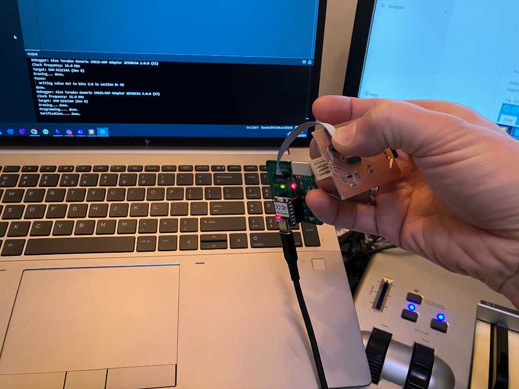
A check that it worked is that I now have another COM port. Done! Bootloaded my first SAM-D!
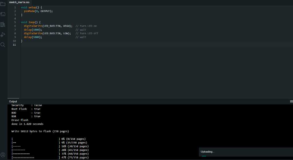
LED blinking
Let’s blink the LED. pin numbers are very straightforward. But to be sure how to address which pin in Arduino IDE, I checked this file. I have my LED connected to PA09.
WS2812B/Neopixel
Now let’s see if the WS2812B works. It is connected to pin PA05.
There are 2 widely used libraries to control this LED: FastLED (mostly used, I’ve used it before too) and Neopixel (the “original” by Adafruit). First let’s go for FastLED. I already have the library installed.
Here’s the code that I made:
#include <FastLED.h>

#define LED 9;
#define WS2812BPIN 5;
#define NUM_LEDS 1
CRGB leds[NUM_LEDS];
#define STARTLEDDELAY 100
#define NEOPIXELDELAY 500

void setup() {
  pinMode(9, OUTPUT);
  digitalWrite(LED, HIGH); // turn LED on
  FastLED.addLeds<NEOPIXEL, WS2812BPIN>(leds, NUM_LEDS);
  delay(STARTLEDDELAY); // wait
  digitalWrite(LED, LOW); // turn LED off
  delay(STARTLEDDELAY); // wait
}

void loop() {
  leds[0] = CRGB::White;
  FastLED.show();
  delay(NEOPIXELDELAY);
  leds[0] = CRGB::Black;
  FastLED.show();
  delay(NEOPIXELDELAY);
}
The code turns the onboard LED on, initializes the FastLED object, turns the onboard LED off and then starts to blink the WS2812B full white.
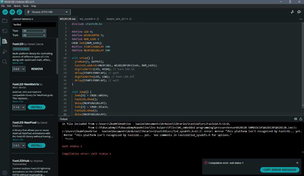
Oops, a compilation error. This platform isn't recognized by FastLED. Too bad. It appears the SAMD11C14A is not supported. Strange, because the SAMD21 and SAMD51 series are supported.
Well, let’s try the Neopixel libary. Again I have this library already installed. The code that I’m going to try which cycles through Red, Green, Blue and Off:
#include <Adafruit_NeoPixel.h>
#define PIN 5
#define NUMPIXELS 1
#define LED 9
Adafruit_NeoPixel pixels(NUMPIXELS, PIN, NEO_GRB + NEO_KHZ800);
#define STARTLEDDELAY 100
#define NEOPIXELDELAY 500

void setup() {
  pinMode(LED, OUTPUT);
  pixels.begin();
  digitalWrite(LED, HIGH); // turn LED on
  delay(STARTLEDDELAY); // wait
  pixels.clear();
  digitalWrite(LED, LOW); // turn LED off
  delay(STARTLEDDELAY); // wait
}

void loop() {
  pixels.setPixelColor(0, pixels.Color(255, 0, 0));
  pixels.show();
  delay(NEOPIXELDELAY);
  pixels.setPixelColor(0, pixels.Color(0, 255, 0));
  pixels.show();
  delay(NEOPIXELDELAY);
  pixels.setPixelColor(0, pixels.Color(0, 0, 255));
  pixels.show();
  delay(NEOPIXELDELAY);
  pixels.setPixelColor(0, pixels.Color(0, 0, 0));
  pixels.show();
  delay(NEOPIXELDELAY);
}
This code compiles nicely.
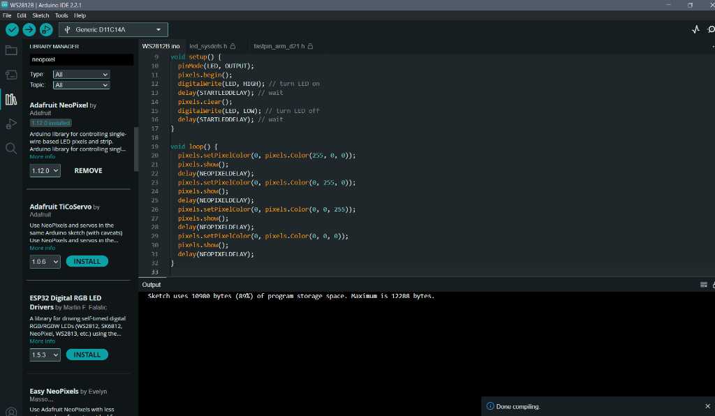
And that works too. The memorysize of this microcontroller is limited. I was not able to use one of the rainbow examples of the Neopixel Libary:
#include <Adafruit_NeoPixel.h>
#define PIN 5
#define NUMPIXELS 1
Adafruit_NeoPixel pixels(NUMPIXELS, PIN, NEO_GRB + NEO_KHZ800);
#define NEOPIXELDELAY 50

void setup() {
  pixels.begin();
  pixels.clear();
  pixels.setBrightness(50); // Set BRIGHTNESS to about 1/5 (max = 255)
}

void loop() {
  for(long firstPixelHue = 0; firstPixelHue < 65536; firstPixelHue += 256) {
    int color = pixels.gamma32(pixels.ColorHSV(firstPixelHue)); // hue -> RGB
    pixels.setPixelColor(0, color); // Set pixel 'c' to value 'color'
    pixels.show(); // Update strip with new contents
    delay(NEOPIXELDELAY);  // Pause for a moment
  }
}
Although this sketch uses 11956 bytes (97%) of program storage space. And maximum is 12288 bytes, it still doesn’t want to upload:
file operation exceeds flash size
Atmel SMART device 0x10030006 found
Device       : ATSAMD11C14A
Chip ID      : 10030006
Version      : v2.0 Aug 31 2021 14:06:56
Address      : 4096
Pages        : 192
Page Size    : 64 bytes
Total Size   : 12KB
Planes       : 1
Lock Regions : 16
Locked       : none
Security     : false
Boot Flash   : true
BOD          : true
BOR          : true
Erase flash
done in 2.061 seconds

Failed uploading: uploading error: exit status 1
The SAM-D11C14A has 16kB flash memory for the program. The Arduino bootloader already takes up 4kB, leaving 12kB for my own program but my program includes all Arduino overhead. If I compile an empty Arduino project like this one:
void setup() {

}
void loop() {

}
the sketch uses 9716 bytes (79%) of program storage space. So it’s a /small chip :D
According to the ArduinoCore-samd github page there is a way to reduce the codesize a bit. This is done by enabling config.h in the Arduino Tools menu:
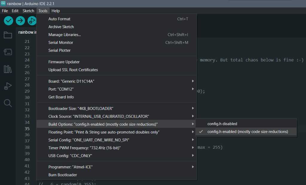
By doing this, the code size goes down to 11296 bytes (91%) and thus reducing 660 Bytes. Enough to properly upload and work!
I’m not going to worry more about this right now, because I don’t intent to use this specific chip in my final project. I’ll use one with more flash memory.
Button pressing
Time to check if the button works. I’ve connected it to PA08. Every button needs debouncing. And the internet is full of debouncing code. One more elaborate than the other. Here’s an interesting blog to read. I used the proposed code to debounce by button.
#include <Adafruit_NeoPixel.h>
#define NEOPIXELPIN 5
#define NUMPIXELS 1
#define LEDPIN 9
#define BUTTONPIN 8
Adafruit_NeoPixel pixels(NUMPIXELS, NEOPIXELPIN, NEO_GRB + NEO_KHZ800);
#define STARTLEDDELAY 100
#define BUTTONDELAY 10

void setup() {
  pinMode(LEDPIN, OUTPUT); // set LED pin to output
  pixels.begin();
  digitalWrite(LEDPIN, HIGH); // turn LED on
  delay(STARTLEDDELAY); // wait
  pixels.clear();
  pixels.setBrightness(50); // Set BRIGHTNESS to about 1/5 (max = 255)
  pinMode(BUTTONPIN, INPUT_PULLUP); // set button pin to input. Use pullup because the button is connected to GND.

  digitalWrite(LEDPIN, LOW); // turn LED off
  delay(STARTLEDDELAY); // wait
}

void loop() {
  int R, G, B; // initialize integers to hold color information
  if (debouncedButton()) {
    randomColor(R, G, B); // call randomizer function
    pixels.setPixelColor(0, R, G, B); // set the pixel colors
    pixels.show(); // Update Neopixel with new content

  };
  delay(BUTTONDELAY);
}

void randomColor(int & R, int & G, int & B) { // a function that randomly set a value to R, G and B. It passes these variables by reference (&) so changes affect the original variable.
  R = random(0,255);
  G = random(0,255);
  B = random(0,255);
}

bool debouncedButton() { // debounce function for 1 button. See https://www.e-tinkers.com/2021/05/the-simplest-button-debounce-solution/
  static uint16_t state = 0;
  state = (state<<1) | digitalRead(BUTTONPIN) | 0xfe00;
  return (state == 0xff00);
}
And to simulate a properly bouncing connection, I don’t use an actual pushbutton, but a jumperwire instead, yikes! But it behaves nicely. On every “press” I get a random LED color as intended:
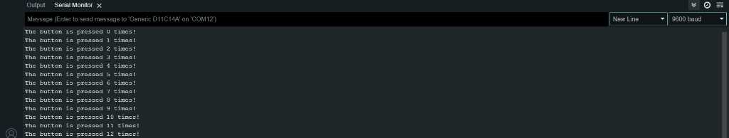
RS232 communication
As the memory of this chip is limited, I cannot use both RS232 and Neopixel at the same time. So I made this small script which turns the LED on and off at each buttonpress, counts the amount of presses and sends that to the serial monitor:
#define LEDPIN 9
#define BUTTONPIN 8
#define STARTLEDDELAY 100
#define BUTTONDELAY 10

void setup() {
  pinMode(LEDPIN, OUTPUT); // set LED pin to output
  digitalWrite(LEDPIN, HIGH); // turn LED on
  delay(STARTLEDDELAY); // wait
  Serial.begin(9600); // enable serial communication
  pinMode(BUTTONPIN, INPUT_PULLUP); // set button pin to input. Use pullup because the button is connected to GND.

  digitalWrite(LEDPIN, LOW); // turn LED off
  delay(STARTLEDDELAY); // wait
}

void loop() {
  static bool ledState;
  if (debouncedButton()) { // only do this when button is pressed
    static int x; // a place to store the amount of button presses. static because it needs to keep its value when it loops.
    ledState = !ledState;
    Serial.println((String)"The button is pressed " + x + " times!"); // print the color to the serial monitor, using (String) to typecast
    x++;
  }
  digitalWrite(LEDPIN, ledState); // turn LED on or off
  delay(BUTTONDELAY);
}

bool debouncedButton() { // debounce function for 1 button. See https://www.e-tinkers.com/2021/05/the-simplest-button-debounce-solution/
  static uint16_t state = 0;
  state = (state<<1) | digitalRead(BUTTONPIN) | 0xfe00;
  return (state == 0xff00);
}
And this works as expected:
Analog-to-digital
Let’s see if I can use the ADC of this microcontroller. The pressuresensor is connected to PA04 like this:
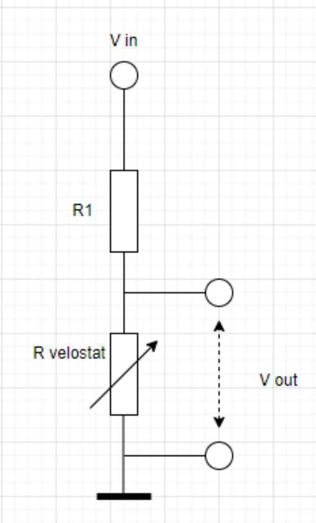
Where R1 is 1KOhm. I’m going to measure Vout using the ADC and see what it does.
I created this code to measure the pressuresensor using the ADC and convert it into a color for the WS2812B:
#include <Adafruit_NeoPixel.h>
#define LEDPIN 9
#define STARTLEDDELAY 100
#define SENSORPIN 4
#define LOOPDELAY 10
#define NEOPIXELPIN 5
#define NUMPIXELS 1
Adafruit_NeoPixel pixels(NUMPIXELS, NEOPIXELPIN, NEO_GRB + NEO_KHZ800);

void setup() {
  pinMode(LEDPIN, OUTPUT); // set LED pin to output
  digitalWrite(LEDPIN, HIGH); // turn LED on
  delay(STARTLEDDELAY); // wait
//  Serial.begin(9600); // enable serial communication
  pinMode(SENSORPIN, INPUT); // set sensor pin to input.
  pixels.begin();
  pixels.clear();
  pixels.setBrightness(50); // Set BRIGHTNESS to about 1/5 (max = 255)
  digitalWrite(LEDPIN, LOW); // turn LED off
//  Serial.println("Starting the measurement");
}

void loop() {
  int ADCMeasurement;
  ADCMeasurement = analogRead(SENSORPIN);
//  Serial.println((String)"Measurement value = " + ADCMeasurement);
  int pixelColor = map(ADCMeasurement, 900, 1023, 0, 65535); // map(value, fromLow, fromHigh, toLow, toHigh)
  int color = pixels.gamma32(pixels.ColorHSV(pixelColor)); // hue -> RGB
  pixels.setPixelColor(0, color); // Set pixel 'c' to value 'color'
  pixels.show(); // Update strip with new contents
  delay(LOOPDELAY); // slow down the loop to give time for proper measurements
}
Alright so this looks promising. However, I had to do a small trick. I use map(ADCMeasurement, 900, 1023, 0, 65535) to map the ADC result to a hue value (color) for the RGB. However, I only map the ADC result between 900 and 1023. Not between 0 and 1023! That’s because I first used a Serial.println statement to print the ADC values. No matter how hard I pressed, I couldn’t get them below 900. I measured the resistance of my pressure sensor using a multimeter and it is in Mega Ohms order of magnitude instead of kilo Ohms. So although the idea works, it’s not “sensitive” enough. I will talk about this more in my final project page on pressure sensor design.
Xiao RP2040 PIO: I2C communication
I want to try if I can setup communication between 2 microcontrollers. I have a SAMD11C14A and the Xiao RP2040 on the Quentorres. The I2C pins on the Quentorres are not connected to anything on the board. But there are a few other pins connected to a breakout connector. Maybe I can program them using PIO to act like a I2C bus.
Henk sent a link to a nice tutorial of Digikey on how to use PIO on the Raspberry Pi Pico. It should work on the Xiao RP2040 as well.
PIO is short for Programmable Input Output and is considered one of the features that adds the most coolness to the RP2040. It allows you to program any pin to act as basically every “advanced peripheral” you like. For example I2S, CAN bus or SD card lines. The microcontroller has 2 PIO instances and each instance can run a tiny program (maximum 32 assembly instructions) independently of the main core processor. They are still clocked by the same system clock. They’re like special tiny little microcontrollers specifically designed to handle all kind of communication protocols.
The inner working of the PIO is explained in chapter 3 of the RP2040 datasheet. Each PIO instance has 4 independent state machines that use instructions coming from a shared instruction memory. The state machines have buffers to input or output data and interrupts so they can be synced to other state machines or the main CPU.
Each state machine has its own program counter that is required to run independently. The state machines are not designed to do any math. It’s only designed to move data around and toggle pins. The 9 available instructions are JMP, WAIT, IN, OUT, PUSH, PULL, MOV, IRQ, SET. See chapter 3.2.1.
There’s also a PIO section in the C/C++ SDK development guide, again chapter 3. This explains what needs to be done to configure state machines and upload programs to PIO memory. The documentation of each and every SDK function can be found at raspberrypi.github.io. Examples of pio files can be found here.
The tutorial uses VSCode, but this is not required. It is required though to install the Pico C/C++ SDK and build system. On Linux and Mac this is easy to install. Windows not so much, so they recommend this tutorial (how to set up raspberry pi pico toolchain on windows with VS Code). This tutorial uses MinGW in place of the Build Tools for Visual Studio.
But I have windows subsystem for linux, so I think I’ll do it this way:
cd ~
mkdir picotools
wget https://raw.githubusercontent.com/raspberrypi/pico-setup/master/pico_setup.sh
chmod -x pico_setup.sh
. pico_setup.sh
It looked ok for a long time but eventually this gave an error when trying to build picotool:
-- Could NOT find PkgConfig (missing: PKG_CONFIG_EXECUTABLE)
-- Could NOT find LIBUSB (missing: LIBUSB_INCLUDE_DIR)
CMake Error at CMakeLists.txt:34 (message):
  picotool cannot be built because libUSB is not found
After checking I noticed that pkg-config was not installed on my linux WSL. So:
sudo apt-get install pkg-config
And start over again:
rm -rf pico
. pico_setup.sh
Now it fails a little bit again, because after building all tools, it wants to install VSCode and do some UART stuff to be able to use it for the pico. But I don’t want any of that. I just wanted to have the pico-tools. I checked using the command printenv and I see occurances of the picoSDK here. So that’s good.
Now let’s see if I can blink the build-in LED using a PIO program.
I continued following the tutorial and added files:
leo@5CG3515MYG:~$ mkdir blinkPio
leo@5CG3515MYG:~$ cd blinkPio
leo@5CG3515MYG:~/blinkPio$ touch blink.pio
leo@5CG3515MYG:~/blinkPio$ vi blink.pio
leo@5CG3515MYG:~/blinkPio$ touch main.c
leo@5CG3515MYG:~/blinkPio$ vi main.c
leo@5CG3515MYG:~/blinkPio$ touch CMakeLists.txt
leo@5CG3515MYG:~/blinkPio$ vi CMakeLists.txt
In vi I copied the given example codes.
At this point I have all the files necessary to build and run my blink PIO program. So time to build:
leo@5CG3515MYG:~/blinkPio$ cmake .
leo@5CG3515MYG:~/blinkPio$ make
That gave me lots of files. Most importantly blink_pio.uf2 which I can upload to the Xiao when it is in bootloader mode.
now that’s a fast blinking LED! I think I should collect blinking LED videos…
So this did exactly what we expected. Let’s continue to I2C.
After installing the pico C/C++ SDK there are a few examples installed as well. To build them:
cd pico
cd pico-examples
cmake .
make
It’s going to build all examples. Not necessarily what I wanted, but I’ll take it as a bonus.
The PIO I2C example is in pico-examples/pio/i2c
Quentorres has a 7 pin connector right next to the Xiao that has:
1 PWR_5V
2 GND
3 PWR_3V3
4 SWD_SWDIO -> connected to D10 of the Xiao
5 SWD_SWCLK -> connected to D9 of the Xiao
6 SWD_RST
7 SWD_LED
I want to use pin 4 SWD_SWDIO -> D10 as I2C SDA and pin 5 SWD_SWCLK -> D9 as I2C SCL. So I changed the i2c_bus_scan.c file accordingly. I also added a while(true) and a sleep_ms(2000) so the scanning will continuously run, every 2 seconds.
I want the scan result to be output on the USB serial port. To do this I’ve added the following lines to CmakeLists.txt file as instructed by this small tutorial.
pico_enable_stdio_usb(pio_i2c_bus_scan 1)
pico_enable_stdio_uart(pio_i2c_bus_scan 0)
Somehow I couldn’t get this USB serial to work. So I reverted to Arduino IDE. I copied the pio_i2c.c, pio_i2c.h and i2c.pio.h files that I made/build to to new folder and converted the i2c scanner code to an Arduino code that looks like this:
// https://www.instructables.com/Using-RP2040-PIO-in-Arduino-IDE-on-Windows/
// https://github.com/raspberrypi/pico-sdk
// https://datasheets.raspberrypi.org/pico/raspberry-pi-pico-c-sdk.pdf chapter 3.3
// https://forum.arduino.cc/t/undefined-reference-error/571942/5

extern "C" {
  #include "pio_i2c.h"
}

#define PIN_SDA 9
#define PIN_SCL 10

PIO pio = pio0;
uint sm = 0;
uint offset = pio_add_program(pio, &i2c_program);

bool reserved_addr(uint8_t addr) {
  return (addr & 0x78) == 0 || (addr & 0x78) == 0x78;
}

void setup() {
  // put your setup code here, to run once:
  pinMode(LED_BUILTIN, OUTPUT);
  Serial.begin(9600);
  i2c_program_init(pio, sm, offset, PIN_SDA, PIN_SCL);
}

void loop() {

  // put your main code here, to run repeatedly:
  static int loop;
  digitalWrite(LED_BUILTIN, HIGH);  // turn the LED on (HIGH is the voltage level)
  Serial.print("/");
  loop++;
  delay(1000);                      // wait for a second
  digitalWrite(LED_BUILTIN, LOW);   // turn the LED off by making the voltage LOW
  delay(1000);                      // wait for a second

  if (loop == 10) {
    Serial.print("\nPIO I2C Bus Scan\n");
    Serial.print("   0  1  2  3  4  5  6  7  8  9  A  B  C  D  E  F\n");

    for (int addr = 0; addr < (1 << 7); ++addr) {
        if (addr % 16 == 0) {
            Serial.print((String)addr + "x ");
        }
        // Perform a 0-byte read from the probe address. The read function
        // returns a negative result NAK'd any time other than the last data
        // byte. Skip over reserved addresses.
        int result;
        if (reserved_addr(addr))
            result = -1;
        else
            result = pio_i2c_read_blocking(pio, sm, addr, NULL, 0);

        Serial.print(result < 0 ? "." : "@");
        Serial.print(addr % 16 == 15 ? "\n" : "  ");
    }
    loop = 0;
  }
}
Note that I had to use extern C to indicate that i2c.pio.h is a proper C file and not a C++ file. Otherwise build would fail.
I’ve connected the Quentorres using GND, SWD_SWIO and SWD_SWSCLK to my SAMD PCB. On the SAMD PCB I compiled and uploaded the following I2C test program which I learned from deepBlueMbedded:
/*
* adapted version of:
* LAB Name: Arduino I2C Slave(Tx)
* Author: Khaled Magdy
* For More Info Visit: www.DeepBlueMbedded.com
*/

#include <Wire.h>
#define BTN_PIN 8

byte TxByte = 0;

void I2C_TxHandler(void)
{
  Wire.write(TxByte);
}

void setup() {
  pinMode(BTN_PIN, INPUT_PULLUP);
  Wire.begin(0x55); // Initialize I2C (Slave Mode: address=0x55 )
  Wire.onRequest(I2C_TxHandler);
}

void loop() {
  byte BtnData = 0;
  BtnData |= digitalRead(BTN_PIN) << 0;
  TxByte = BtnData;
  delay(10);
}
Now I don’t think this runs as expected. The output of the I2C scanner should have been that it kept on detecting address 0x55. But instead:
////////
PIO I2C Bus Scan
   0  1  2  3  4  5  6  7  8  9  A  B  C  D  E  F
0x .  .  .  .  .  .  .  .  .  .  .  .  .  .  .  .
16x .  .  .  .  .  .  .  .  .  .  .  .  .  .  .  .
32x .  .  .  .  .  .  .  .  .  .  .  .  .  .  .  .
48x .  .  .  .  .  .  .  .  .  .  .  .  .  .  .  .
64x .  .  .  .  .  .  .  .  .  .  .  .  .  .  .  .
80x .  .  .  .  .  .  .  .  .  .  .  .  .  .  .  .
96x .  .  .  .  .  .  .  .  .  .  .  .  .  .  .  .
112x .  .  .  .  .  .  .  .  .  .  .  .  .  .  .  .

//////////
PIO I2C Bus Scan
   0  1  2  3  4  5  6  7  8  9  A  B  C  D  E  F
0x .  .  .  .  .  .  .  .  .  .  .  .  .  .  .  .
16x .  .  .  .  .  .  .  .  .  .  .  .  .  .  .  .
32x .  .  .  .  .  .  .  .  .  .  .  .  .  .  .  .
48x .  .  .  .  .  .  .  .  .  .  .  .  .  .  .  .
64x .  .  .  .  .  .  .  .  .  .  .  .  .  .  .  .
80x .  .  .  .  .  .  .  .  .  .  .  .  .  .  .  .
96x .  .  .  .  .  .  .  .  @  @  .  .  .  .  .  .
112x .  .  .  .  .  .  .  .  .  .  .  .  .  .  .  .

//////////
PIO I2C Bus Scan

   0  1  2  3  4  5  6  7  8  9  A  B  C  D  E  F
0x .  .  .  .  .  .  .  .  .  .  .  .  .  .  .  .
16x .  .  .  .  .  .  .  .  .  .  .  .  .  .  .  .
32x .  .  .  .  .  .  .  .  .  .  .  .  .  .  .  .
48x .  .  .  .  .  .  .  .  .  .  .  .  .  .  .  .
64x .  .  .  .  .  .  .  .  .  .  .  .  .  .  .  .
80x .  .  .  .  .  .  .  .  .  .  .  .  .  .  .  .
96x .  .  .  .  .  .  .  .  .  .  .  .  .  .  .  .
112x .  .  .  .  .  .  .  .  .  .  .  .  .  .  .  .

//////////
PIO I2C Bus Scan
   0  1  2  3  4  5  6  7  8  9  A  B  C  D  E  F
0x .  .  .  .  .  .  .  .  .  .  .  .  .  .  .  .
16x .  .  .  .  .  .  .  .  .  .  .  .  .  .  .  .
32x .  .  .  .  .  .  .  .  .  .  .  .  .  .  .  .
48x .  .  .  .  .  .  .  .  .  .  .  .  .  .  .  .
64x .  .  .  .  .  .  .  .  .  .  .  .  .  .  @  @
80x @  @  .  .  .  .  .  .  .  .  .  .  .  .  .  .
96x .  .  .  .  .  .  .  .  .  .  .  .  .  .  .  .
112x .  .  .  .  .  .  .  .  .  .  .  .  .  .  .  .

//////////
PIO I2C Bus Scan
   0  1  2  3  4  5  6  7  8  9  A  B  C  D  E  F
0x .  .  .  .  .  .  .  .  .  .  .  .  .  .  .  .
16x .  .  .  .  .  .  .  .  .  .  .  .  .  .  .  .
32x .  .  .  .  .  .  .  .  .  .  .  .  .  .  .  .
48x .  .  .  .
So it detects something which is all over the place and after 4 attempts it crashes.
Possible causes:
- I’m not sure if I have to explicitly tell the SAMD arduino code which I2C pins to use.
- I’m not sure if the Xiao RP2040 I2C scanner works properly
- I’m not sure if the SAMD I2C Secondary works properly
So I’ll have to test with known working I2C devices I guess.
Fortunately there’s always Good Old Arduino Uno. I programmed this one to act as a I2C bus scanner using this deepbluembedded tutorial. Code is here:
/*
* LAB Name: Arduino I2C Scanner
* Author: Khaled Magdy
* For More Info Visit: www.DeepBlueMbedded.com
*/
#include <Wire.h>

void setup()
{
  Serial.begin(9600);
  Wire.begin();
}
void loop()
{
  byte error, address;
  int nDevices;
  Serial.println("Scanning...");
  nDevices = 0;
  for(address = 1; address < 127; address++ )
  {
    Wire.beginTransmission(address);
    error = Wire.endTransmission();
    if (error == 0)
    {
      Serial.print("I2C device found at address 0x");
      if (address<16)
      { Serial.print("0"); }
      Serial.print(address,HEX);
      Serial.println("  !");
      nDevices++;
    }
    else if (error==4)
    {
      Serial.print("Unknown error at address 0x");
      if (address<16)
      { Serial.print("0"); }
      Serial.println(address,HEX);
    }
  }
  if (nDevices == 0)
  { Serial.println("No I2C devices found\n"); }
  else
  { Serial.println("done\n"); }
  delay(5000);           // wait 5 seconds for next scan
}
My SAMD controller is still programmed with the program as listed above, using address 0x55.
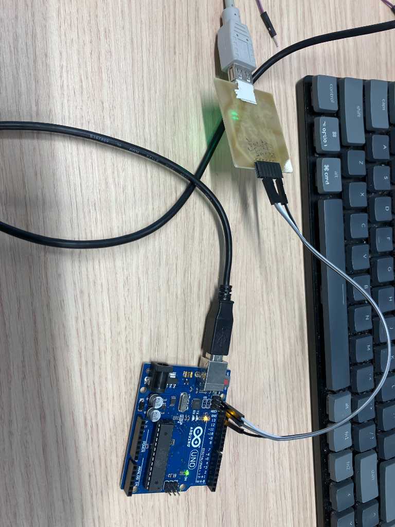
When I connect it to the Arduino UNO I2C pins, this is what happens:
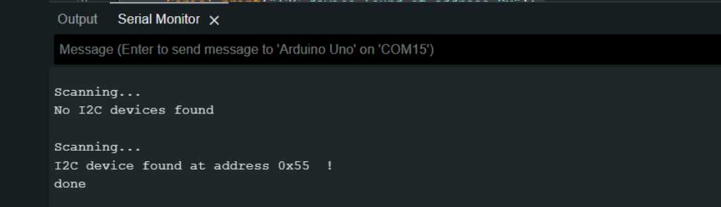
And so I2C on the SAMD works. The UNO is able to get its I2C address. Nice. The other way around works as well by the way. So programming the UNO as Secondart and the SAMD as Main (scanning the bus).
But this also means that there’s something wrong with the Xiao RP2040 program that I used above. #fail
I tried looking up various tutorials on PIO programming specific for I2C, but I couldn’t find any, except for this basic I2C-scanner example. It seems like people like PIO a lot, but it’s that complicated that either nobody really uses it or they keep it for themselves. So the PIO programming story ends here. Fortunately I was able to proof that I can do I2C communication between microcontrollers!
Link to repo
What I learned this week
Successes
This week went well. I was able to get a lot of things done. Some conclusions:
- I’ve been living under a microcontroller rock for the last 15 years. Amazing what modern microcontrollers can do at such a low cost. I actually enjoyed reading about the SAM-D family and then checking its pricetag :-)
- I still don’t like VSCode a lot. All the different extensions that do something but not everything…
- I was able to get some I2C communication going between SAMD and Arduino Uno (ATMega) which was cool
- I played around with PIO which is a totally different level of programming. Nice but unfortunately I couldn’t get I2C to work this way
- Rust and Go are nice but not well supported yet. I didn’t have time to go into more details or do a Rust or Go tutorial. Might do that in the future, but will not use it in my final project.
- I enjoyed using the SAM-D chip. New family for me. I was amazed by its features compared to its price.
Fails & Fixes
PIO programming proofed hard to do. The blinking LED example in the C/C++ SDK worked fine. I was able to add some more statements to slow it down and that worked too. But I had problems getting the I2C Address Scanner to work. It’s really hard to debug PIO so I have no clue what went wrong. It’s not the connection or the cables or my SAMD test board because an I2C Address Scanner on Arduino Uno worked fine.
I think the big issue with PIO is that I couldn’t find any libraries. Not even tutorials of anything more than compiling the C/C++ SDK examples.
It would be great if there would be a library with PIO code, just like any other library. Maybe not to directly include into your code, but a list of PIO files like: If you want a certain communication protocol on a pin that RP2040 doesn’t natively have, then use this piece of PIO code.
The C/C++ SDK example of PIO I2C is only this address scanner. Which is nice, but what you really want is send and receive data via I2C. There’s no working example of that (that I could find).