electronics
I want the Marimbatron to be modular, so I want to create a module board that can drive and measure 19 sensors. This equals 1 Marimbatron octave (octave has 12 notes, but for this key layout to be playable, additional overlapping notes are needed). These module boards connect to the MCU board which also contains the LCD/OLED, buttons, etc.
module boards
Interesting thought of Henk is to use a microcontroller in combination with a multiplexer on each module board. The microcontroller can drive the LEDs, drive the multiplexer, and use its internal ADC to get the pressure level. Next it can send it using I2C to a main microcontroller. Example of a multiplexer would be the 4067 (16 channel analog multiplexer). Microcontrollers can be the SAM-D family. Will not be too expensive because not a lot of pins are needed this way. And has fast ADC so that’ll do I guess :-) So every module board will get its own microcontroller that communicates to the main controller using I2C.
Sensors
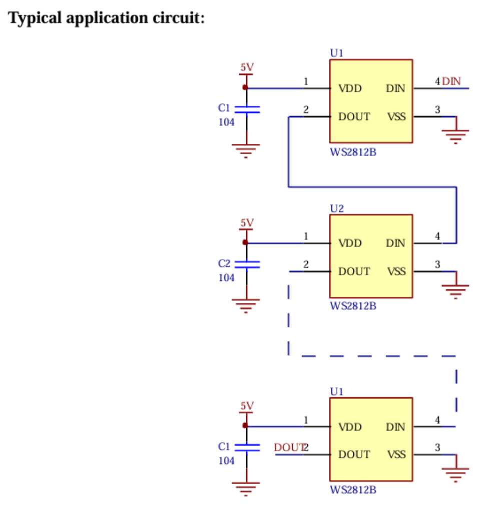
Each sensor will consist of a WS2812 chainable RGB LED (requires 4 wires: Vcc, Di, Do and GND) and a velostat sensor (requires 2 wires: Vsens and GND). Connecting this sensor to a module board would need a flatcable with 5 cores (combined ground). For example: these on Farnell. I don’t see any flatcable shorter than 30mm. Maybe regular wire will work too?
WS2812B RGB LED
Explanation of how WS2812B LEDs work and how to use them in your own custom board: hackster.io.
From the WS2812B datasheet at adafruit:
ADC
Microcontroller ADC speed is important. could be too slow. So this is an important selection criteria for my microcontroller. For example an arduino Uno ADC does a little under 10k samples per second. Other microcontrollers will be faster. The Raspberry RP2040 has 500k samples/sec. I’m not familiar with STM chips but according to this tech note the STM32H7 has a maximum ADC sampling rate of 3.6 Msps in 16-bit mode. The SAM-D21 has a maximum sample rate of 2100 kHz. Another way it to use a I2C/SPI dedicated multichannel ADC chip. Microchip MCP3008 is a 8-channel 10-bit SPI ADC that might be faster. See microchip website . It does 200k samples/second. But that currently feels like an overkill to me.
Multiplexing
A common approach to measuring multiple sensors is by putting them into a grid of columns and rows and multiplex them. So scan the columns and measure the row values.
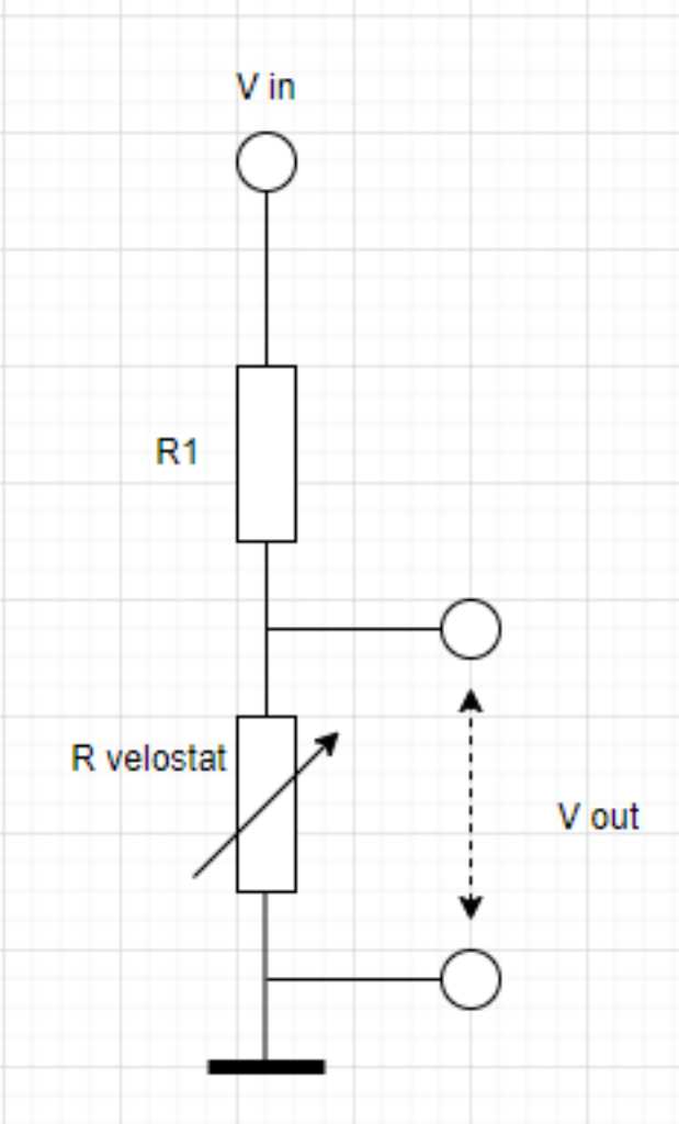
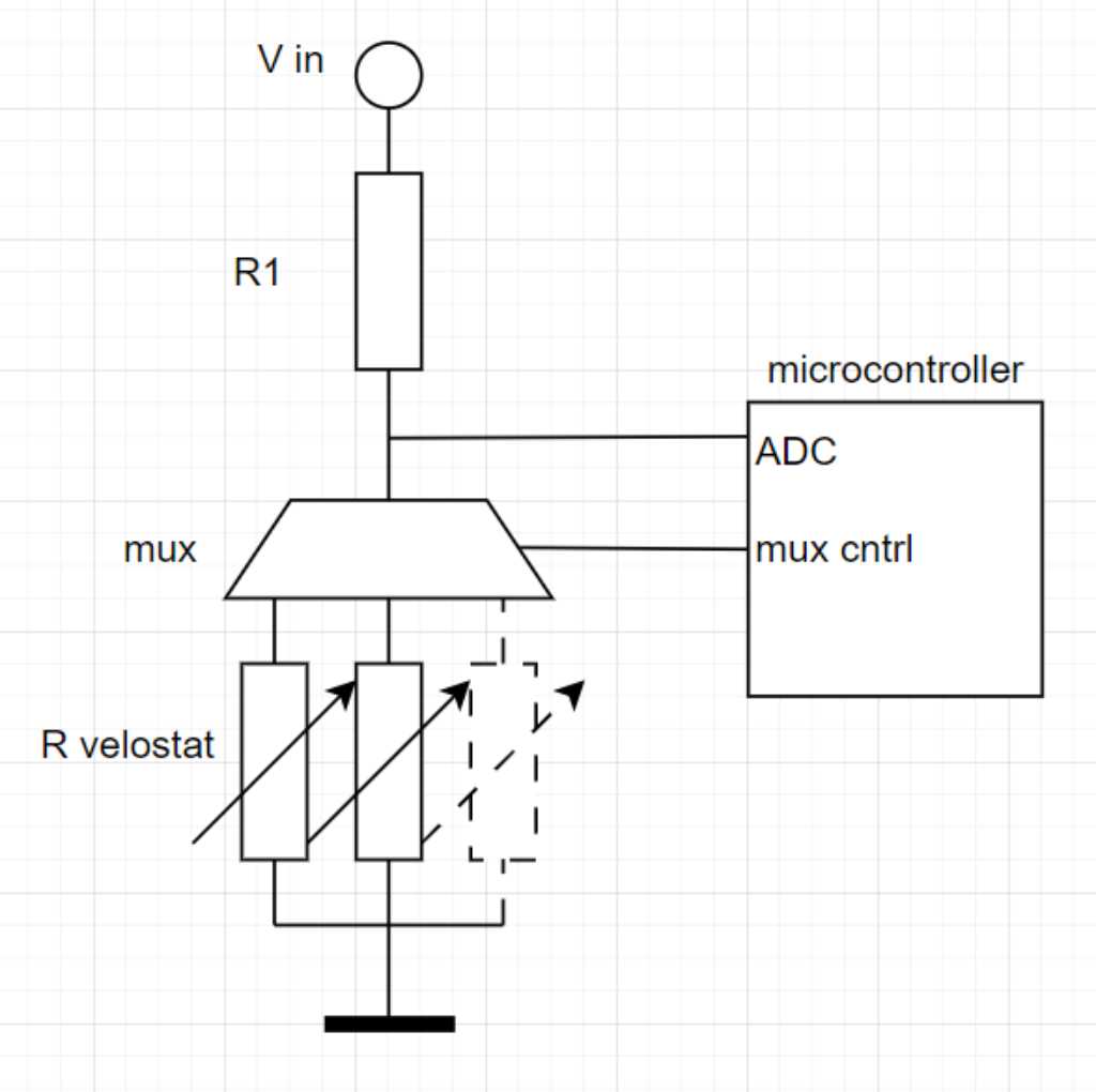
The way to measure the velostat resistance is like this:
To do this in a multiplexed way:
Multiplexers are available in a lot of different version. A standard general purpose mux is the 74HC4067. This is a 16 channel mux. This is the datasheet of TI. The 74HC4051 is it’s 8-channel little brother (datasheet here).
Choosing the right multiplexer is done by comparing a few characteristics and then just choose and try. This is an excellent TI presentation on what to take into account. Critical parameters are:
- On-resistance: for 4067 this is 70 Ohm @ 4.5V typically
- On-capacitance: typically 10pF to 30pF
- Leakage current: typically 8 uA
- Charge injection: pC order of magnitude.

These parameters will hardly influence my measurements. Resistance of my sensor will be in kOhms and MOhms so orders of magnitude higher. The other parameters are interesting when doing high-speed switching (10uS order of magnitude). If I would be able to achieve something like 3ms readtime for 19 channels, my switchingspeed will be something like 150uS. So that’s all fine too. I can just use a general purpose mux, no need to go for something exotic.
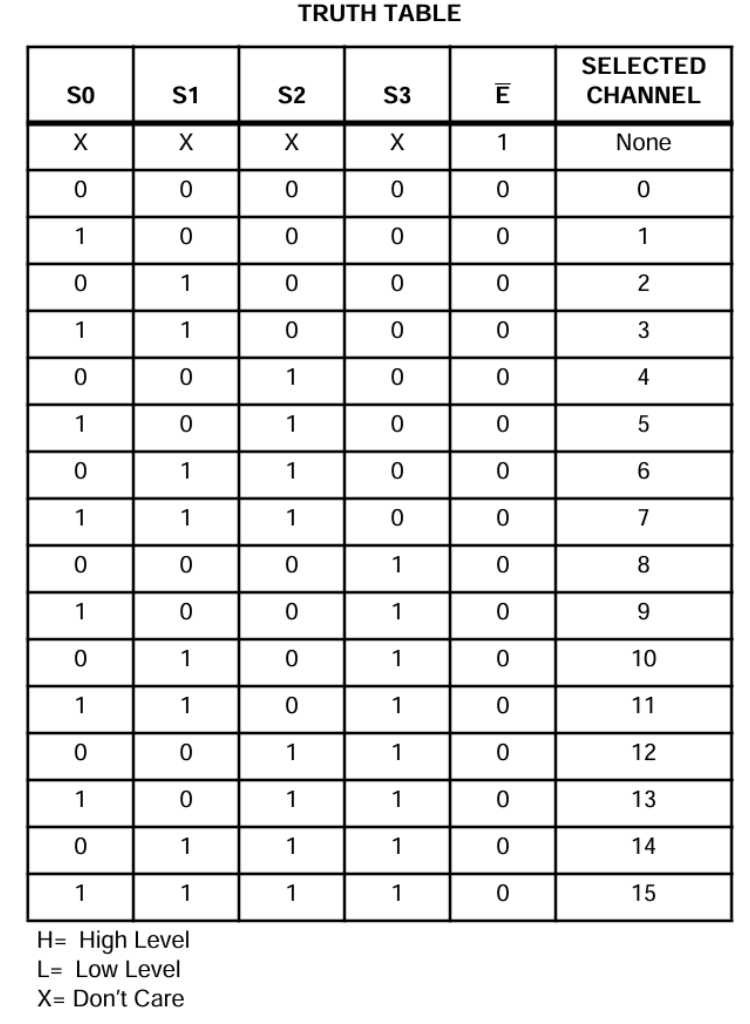
Selecting a channel is done using the S0~S3 pins, according to this truth table:
Microcontroller selection
I’m going to use WS2812B LEDs that are chainable. I need 1 output pin to control them. Every module board will have 19 pressure sensors. So I will need 1x 74HC4051 and 1x 74HC4067 to get 24 channels in total. I will have to switch them on and off individually to I need to use the Enable pin next to all Select pins. That means 5 pins for the 4067 and 4 pins on the 4051, totaling to 9 control pins (I/O) for the multiplexers. This totals to 10 I/O pins that my microcontroller needs to have. The microcontroller also needs at least 1 ADC and I2C for communication.
The selection guide of the SAM microcontrollers can be found here.
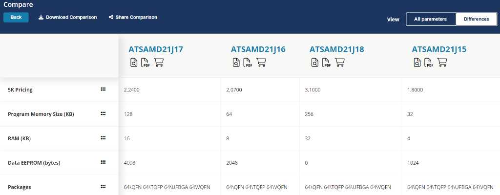
I’m very interested to try the SAM-D family. Interestingly enough, the SAMD21J15, J16, J17 and J18 have 20 ADC channels. I wouldn’t even need to use multiplexers in this case. The only difference is program memory size, RAM and EEPROM size:
ATSAMD11C14 is 1,50 euro per piece. 4051 is 0,66 euro. 4067 is 1,00 euro. Totalling to 3,12 euro per piece.
ATSAMD21J17 is 3,12 euro per piece. And no further soldering required.
Board size final project module board is around 45x70mm.
Main board
The requirements for my main board:
- I2C to communicate to the module boards
- SPI to control a round LCD display
- at least 4 inputs for buttons
- 1 input for a foot pedal
- USB to output midi data
- nice to have: 2 outputs in case I want to use on-board sound synthesis
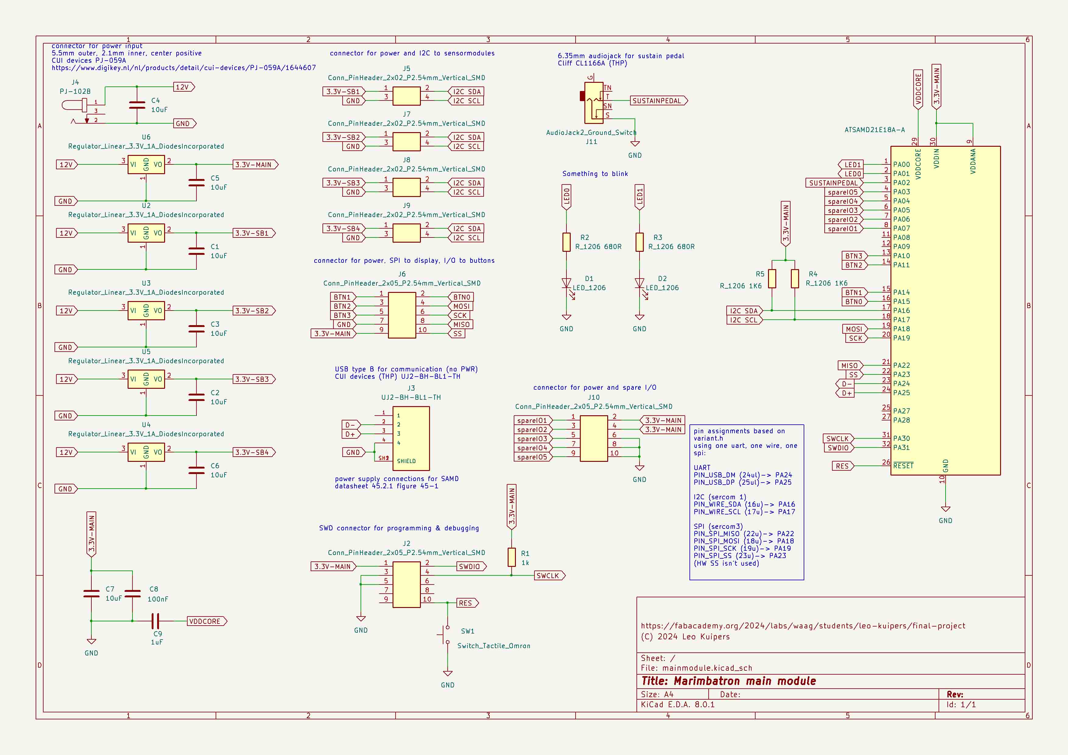
Again this is going to be a microcontroller of the SAM-D family. Perhaps an ATSAMD21E18A (32 pin TQFP).
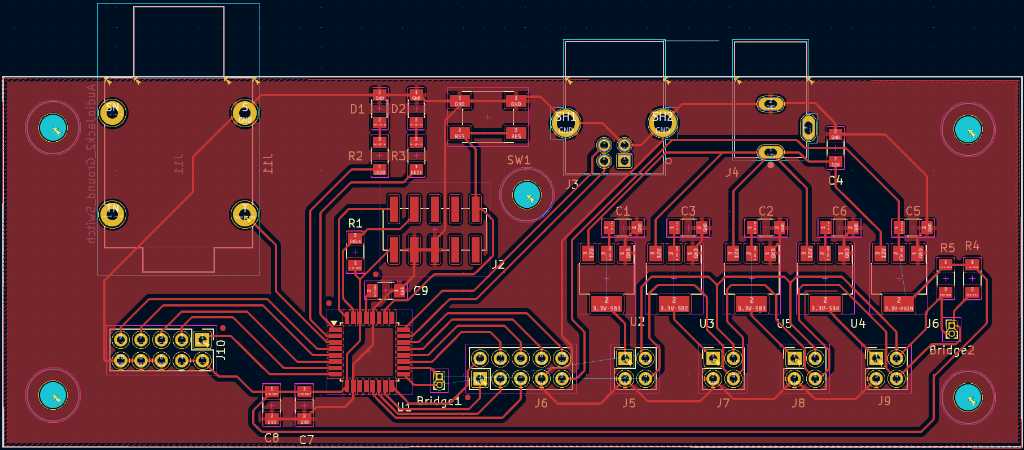
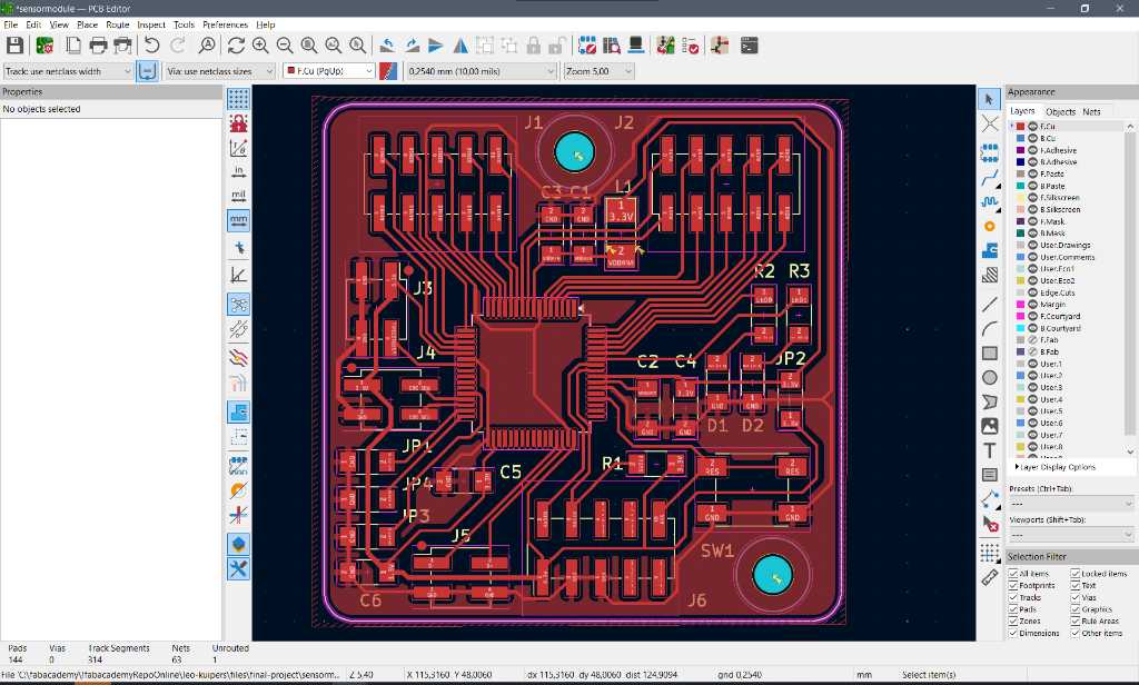
So I created the schematic and board layout in Kicad. Getting the hang of this software tool is nice!
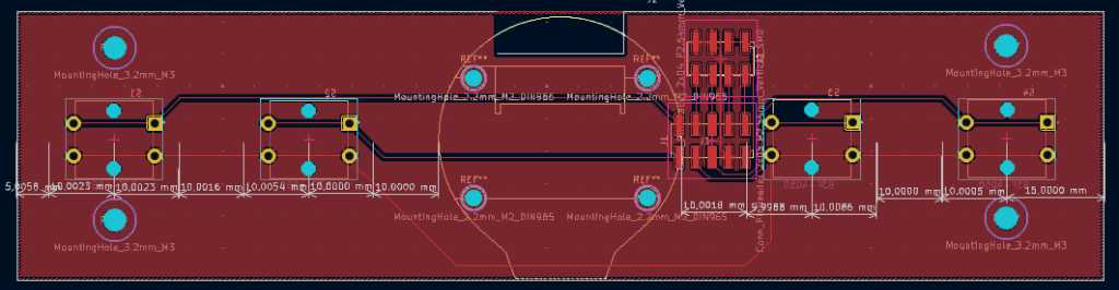
Here are screenshots of the schematic and the PCB design of the main board:
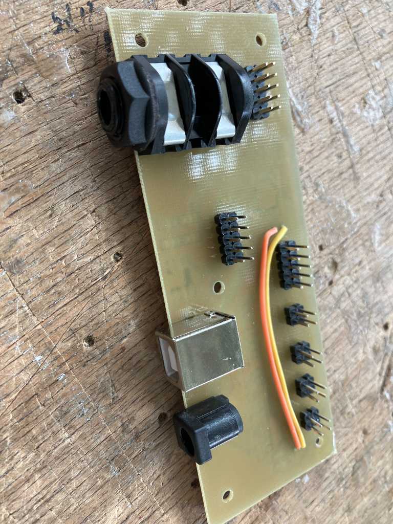
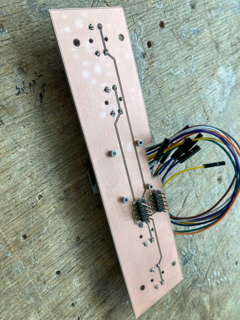
And here’s the main board after assembly. The 2 wires on top are intentionally. This prevents from having a 2-sided PCB for just these wires and also prevents lots of 0 Uhm SMD connectors on the back.
I’ve chosen through-hole connector components due to their better mechanical stability. That meant that I had to use through-hole pin headers too, because otherwise the PCB would become too high to fit into the controller fixture.
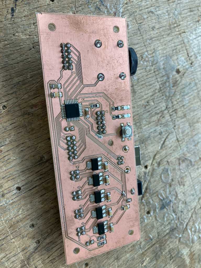
Very quickly (within 24 hours) the copper started to corrode. So I used a conformal coating spray by Kontakt Chemie called Plastik 70.
Source files of this design can be found here in my repo
Power supply
The main board will do power distribution to the sensor module boards. Every board will consume max 1.2A (for the LEDs) + a little bit for the sensors and the microcontroller. So let’s assume 1.3A max. at 3.3V = 4.29W.
There will be maximum 4 octaves in a full Marimbatron, so max 4 sensor boards. That means max 4x1.3A + a bit for the main microcontroller and the display. Let’s assume 5,2A max at 3.3V which is around 17W. That’s a lot! I’ll have to limit the current consumption I think. If I’d use a 5V power supply, this would be 3,4A. At 12V, an 1.5A main power supply will be enough.
But this totally depends on the method and the efficiency of converting from power supply to 3.3V. There are basically 2 way to do this:
- A linear voltage regulator
- A buck regulator (which is a switching step down converter)
Linear voltage regulator
In the Fablab inventory, the AZ1117 linear voltage regulator is a standard part. It can take 18V input voltage maximum and it can output 1.35A maximum.
BUT: The voltage drop that a linear voltage regulator “steps down” will have to go somewhere.****
A linear voltage regulator can be thought of to act like a resistor (it’s actually a voltage controlled current source) whose value is set in such a way that the output is kept at a certain set voltage.
So if input voltage is 12V and output voltage is 3.3V, the voltage drop (12V - 3.3V = 8.7V) is turned into heat. So if for example one sensor board consumes 1A, and there is 8.7V across the linear voltage regulator, the power dissipation in the regulator is P=V x I = 8.7 x 1 = 8.7W! No way that such a small component can dissipate that…
But how much current CAN it do? The absolute maximum ratings in the datasheet of the AZ1117 says the operating junction temperature range is +150° Celcius. But recommended is 125° C.
An explanation of junction temperature can be found in this blog: https://resources.pcb.cadence.com/blog/2020-junction-temperature-vs-ambient-temperature-transistor-temperature-operability.
From this blog, the formula for junction temperature at a given power dissipation is:
Tj = Ta + (Pd * Rja)
Tj is junction temperature
Ta is ambient temperature
Pd is power dissipation
Rja is thermal resistance (junction-to-ambient: how effectively the regulator can dissipate heat)
This means power dissipation Pd = (Tj - Ta) / Rja
Rja (Thermal resistance junction to ambient) = 125°C/W
Tj (max operation junction temperature) = 150°C
Ta (Ambient temperature) = 25°C
So maximum power dissipation is (150 - 25) / 125 = 1W
Recommended power dissipation (125 - 25) / 125 = 0.8 = 800mW
To calculate the maximum current using the recommended power dissipation:
If the voltage across the regulator is 8.7V (12V power supply to 3.3V) and the regulator can only dissipate 800mW, the maximum current is
I = P / V = 0.8 / 8.7 = 0.092A = 92mA.
If the voltage across the regulator is 1.7V (5V power supply to 3.3V) and the regulator can only dissipate 800mW, the maximum current is
I = P / V = 0.8 / 1.7 = 0.471A = 471mA.
What should be remembered is this: A linear voltage regulator can only step down a little bit of voltage, or only with small currents. Not both…
Buck regulator
A buck regulator is basically a really fast switch that switches the power on and off. The pulses that it creates are filtered by an inductor and a capacitor so the output voltage is a nice and clean DC voltage. As there is no resistor in this regulator, a lot less power is dissipated. This increases efficiency drastically.
An example of a buck regulator in SOT23 package is the LT1616. From the datasheet

There are 8 external components needed to get this done. A linear voltage regulator requires just 1 external component. Hence the preference of using that. But with larger currents or lots of voltage drop, a buck regulator is really what you need. Note that this specific type is limited to 600mA.
power from the main board
Unfortunately there is no buck regulator in the Fablab inventory so I’ll have to work with the linear voltage regulator.
That also means that I’ll have to use a 5V input and I cannot go over ~500mA of current. A power supply of 5V 2A should be good enough.
I will use 5 separate 3.3V voltage regulators on the main PCB. One for each sensor board and one for the main board itself (including LCD). Due to component tolerances, each voltage regulator can output a slightly lower or higher output voltage. Worst case, a sensor board has a higher voltage than the main board. This could potentially result in an analog input pin on the main board to go above the Vdd of the main microcontroller. According to the maximum ratings of the SAMD21 the Vpin is allowed to be Vdd+0.6V (table 41-2). That is way more than the voltage difference between voltage regulators. So we should be fine.
I will not connect the outputs of these voltage regulators together. I could do so but again, due to component tolerances, one voltage regulator might do more than the other, and as such can go over its maximum ratings. If one regulator will fail, changes are that the others will fail one after another too (domino).
Sensor module board
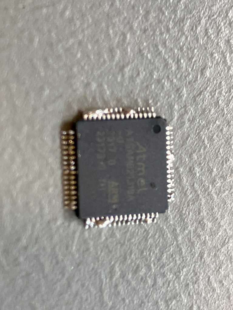
The sensor module board will be based around a SAMD21J18A microcontroller (64 pin TQFP). It has enough ADCs to not have to multiplex.
This microcontroller will communicate to the main microcontroller using I2C. Power to the board will be done through the I2C connector as well.
The microcontroller will drive a string of 19 WS2812B addressable LEDs. One for each sensor. There will be a LED and reset button on the board too. And a USB header for debugging (adds a serial UART).
I originally wanted to daisy-chain multiple sensor module boards using the I2C connector (I2C SDA and SCL + VCC & GND). Unfortunately that will not work because 19x WS2812B will consume at maximum 19 x 60mA = 1.2A. The 1.27mm ribbon cables that I’ll use can only carry 1.4A, so it will be good for 1 sensor board, but not multiple boards. So I’m going to create connectors on the main PCB, one for each sensor board.
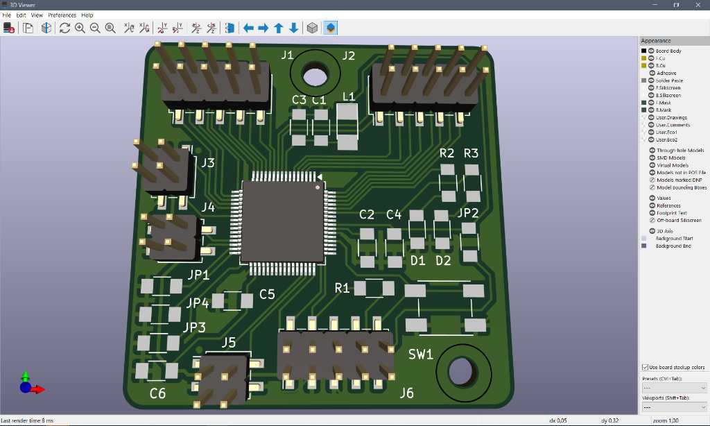
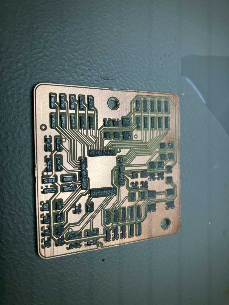
Here’s the schematic and the PCB of the sensor module board:
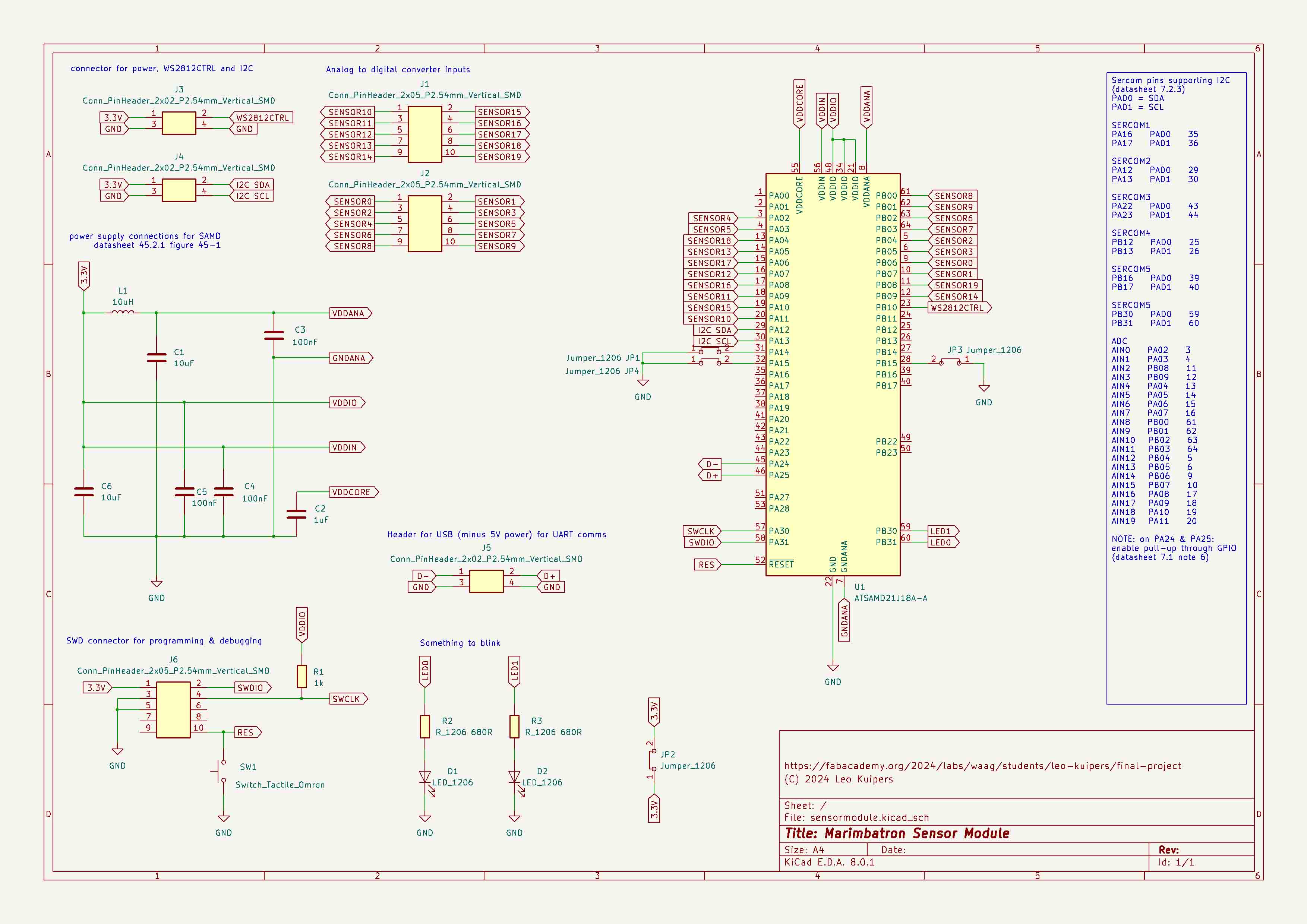
Source files are here in my repo
Creating solder stencil using 100um PET sheet (transparent overhead sheet for inkjet printers). On kiCAD: export paste layer as SVG. In trotec Ruby: convert pads to black, outline to red.
Set both black (engrave) as well as red (cut) to 4% speed and 30% power. Use 1000 DPI (engraving quality).
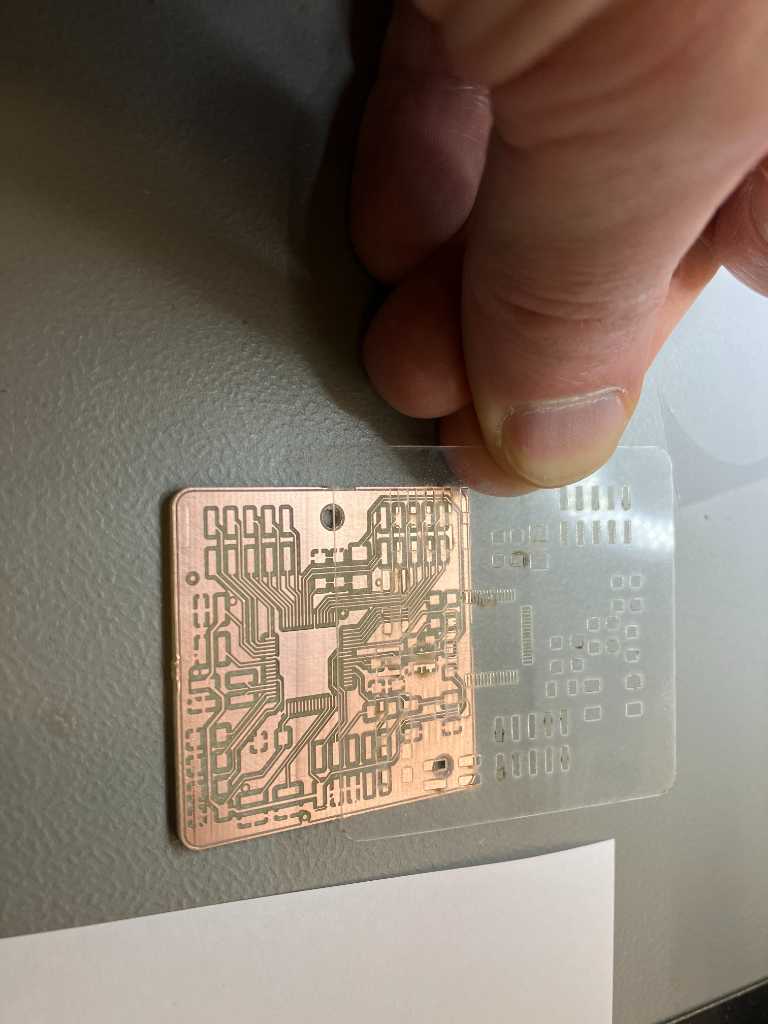
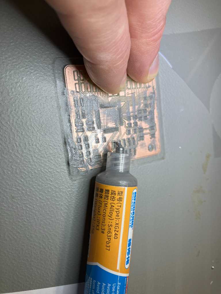
The solder stencil works nice, but the TQFP64 pads of the microcontroller are meh… Not sure if this will work out properly.
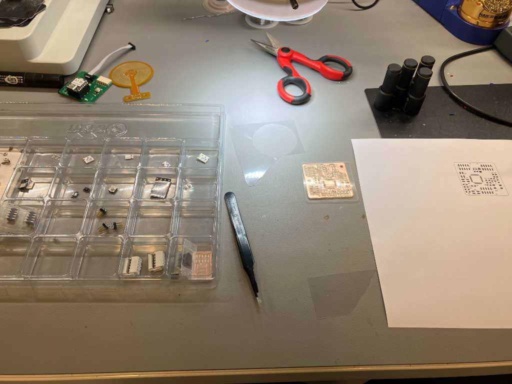
All components placed. Time for the oven.
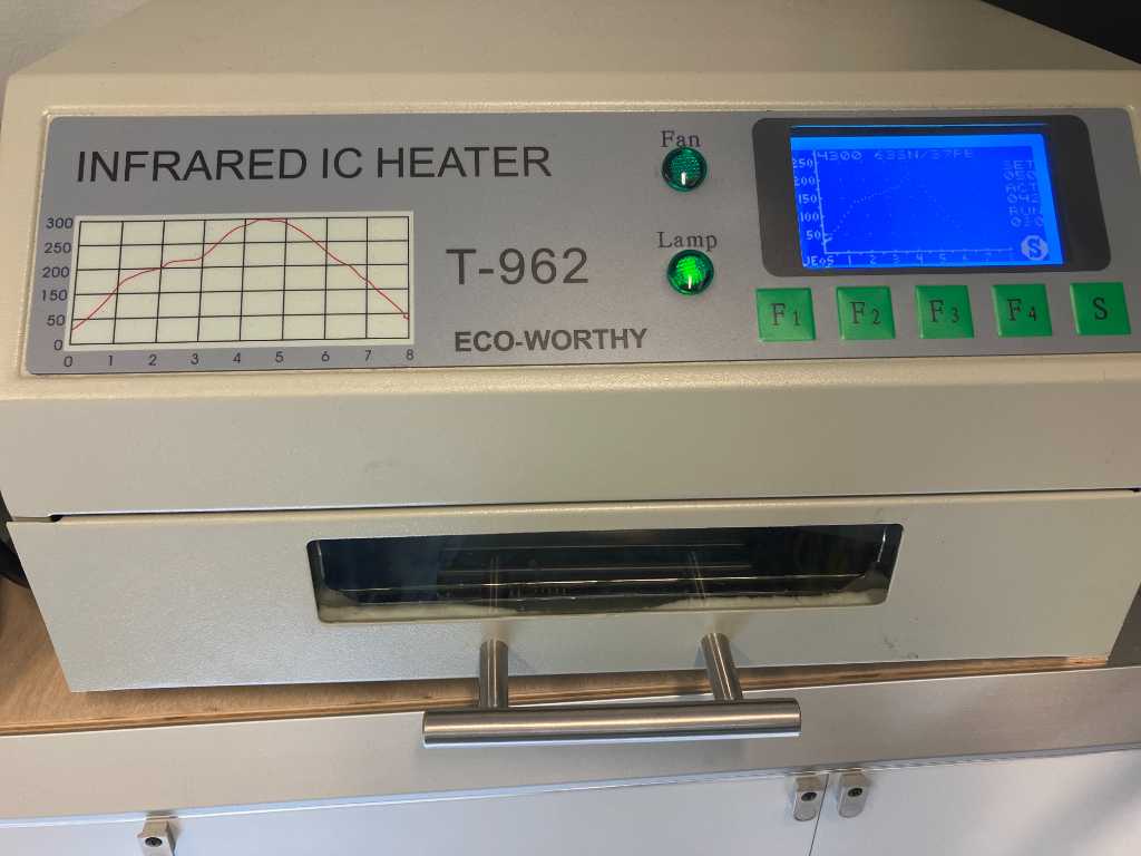
Unfortunately the oven didn’t work out as expected. The solder paste on the pads of the outside of the PCB weren’t fully melted/soldered. And there we’re lots of bridges on the microcontroller pins. That looks nasty:
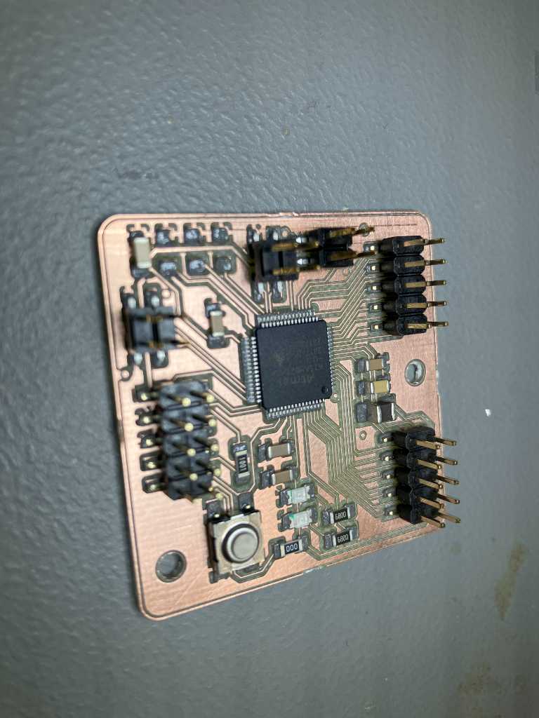
Hot air gun to the rescue! I was able to remove the microcontroller and solder the remaining solder paste. Next I handsoldered a new microcontroller:
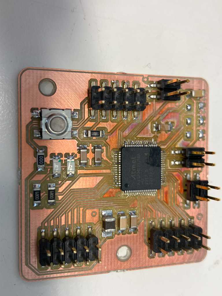
And using a test program I got it to work:
/*
blinkhelloworld-samd21.ino
Leo Kuipers april 2024

inital test of samd21j18a microcontroller.

actual pin numbering of samd21 chips (e.g. portA21 or portB30) is in no way related to arduino pin numbering used in sketches.
To get to the arduino pin number, see https://github.com/qbolsee/ArduinoCore-fab-sam/blob/master/variants/Generic_xx1J/variant.cpp
In this file you'll find the PinDescription table of this microcontroller.
Look for the actual pin number you want to program and check the commented line above it to find the arduino numbering. e.g.
PORTA, 21 on line 130 -> // 12..Digital functions (line 120) -> meaning actual pin number PA21 = arduino number 21
PORTB, 30 on line 166 -> // 43..46 - SPI Header (line 165) -> meaning actual pin number PB30 = arduino number 43

This work may be reproduced, modified, distributed,
performed, and displayed for any purpose, but must
acknowledge this project. Copyright is retained and
must be preserved. The work is provided as is; no
warranty is provided, and users accept all liability.
*/

int counter;
bool led;
const int PB30 = 43; // actual pin number PB30 = arduino pin number 43
const int PB31 = 46; // actual pin number PB31 = arduino pin number 46
void setup() {
  pinMode(PB30, OUTPUT);
  pinMode(PB31, OUTPUT);
  Serial.begin(115200); // start serial communication
//  while (!Serial); // wait for serial port to open before continuing. otherwise the first serial.prints will not be shown in serial monitor. if serial monitor is not opened, the program will not continue.
}

void loop() {
  Serial.print("Hello World! The counter is " );
  Serial.println(counter);
  counter++;
  digitalWrite(PB30, led);
  digitalWrite(PB31, !led);
  led = !led;
  delay(1000);
}
So electronics for my sensor PCB works. Documentation on final programming for this board can be found in final-project/.
more sensor boards
After testing my milled pcb I ordered 6 pieces from Aisler. I also ordered a 100um solder stencil.
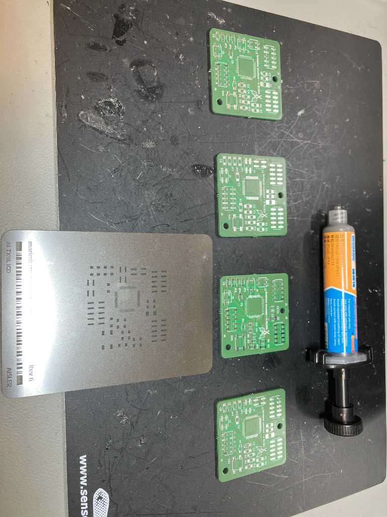
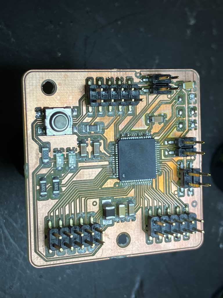
After soldering and programming, they’re all happy!

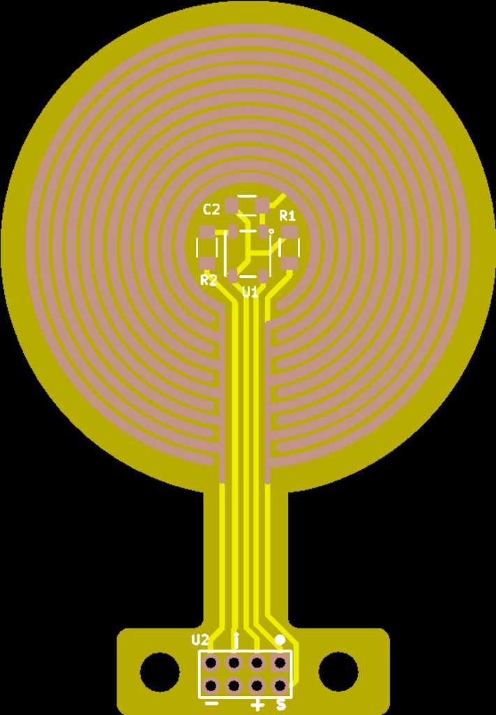
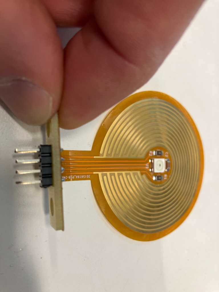
Flexible sensor PCB
I created a flexible PCB to fit into the sensor. I did this during Electronics design week, so you can find the documentation here.
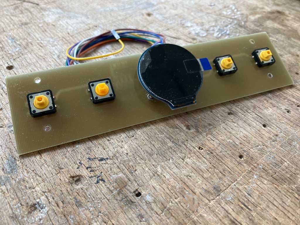
UI interface
The last PCB in the Marimbatron is the UI interface PCB. It consists of 4 switchbuttons and a round LCD made by Waveshare (https://www.waveshare.com/wiki/1.28inch_LCD_Module)
The schematic and PCB design are here:
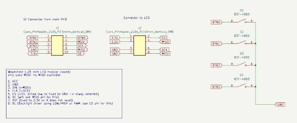
And the kicad files can be found in my repo here.
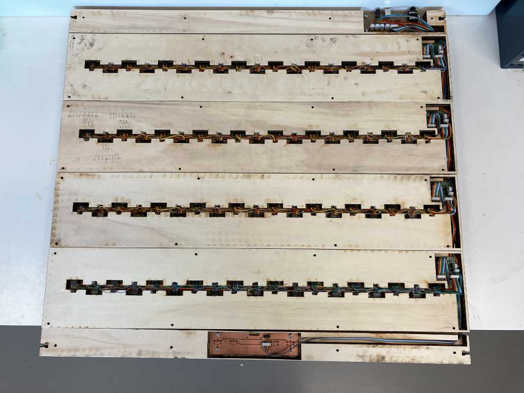
cable management
Cable management is a big thing in the marimbatron. Lots of wires. Per octave: 19 sensor cables, 19 multicables daisy chaining the sensors for power and WS2812B control and 1 multicable for power and I2C to the main PCB.
So I need to create cable harnesses for each sensor fixture.
Wiring is done on the underside of each sensor fixture. First cut them to size and split where needed:
 Using these 8 pin connectors to connect the sensors:
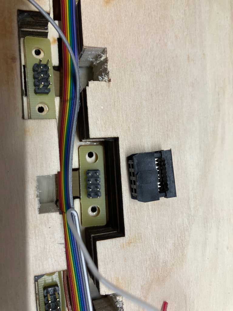
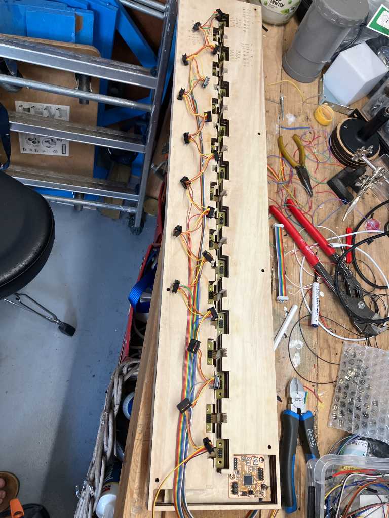
With all connectors attached, it looks like a fine cable harness:
It fits into the cavity so the sensor fixture can lay flat:
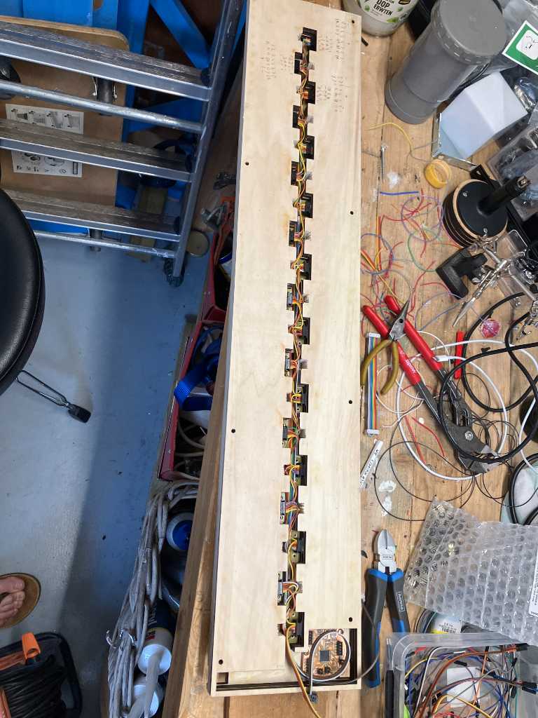
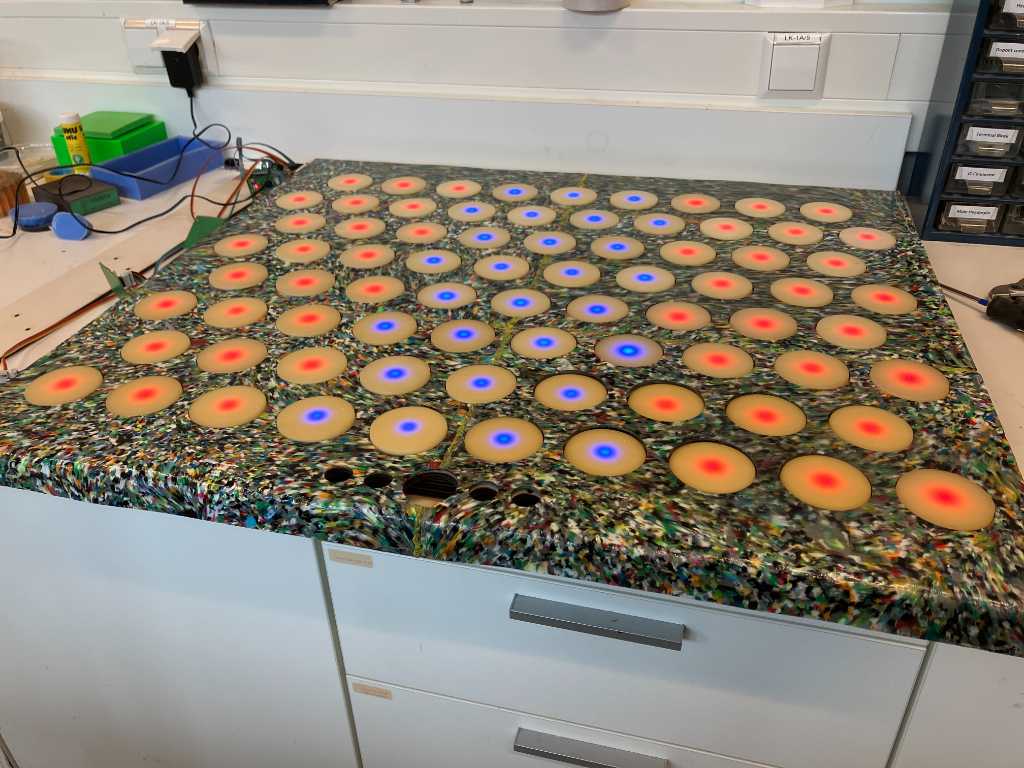
And a first test is to check if all LEDs can be controlled:
Next I will have to repeat this 4 times (because I want 1 spare). First cut the cables to length and split them.
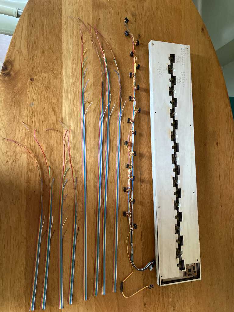
Next connect all connectors:
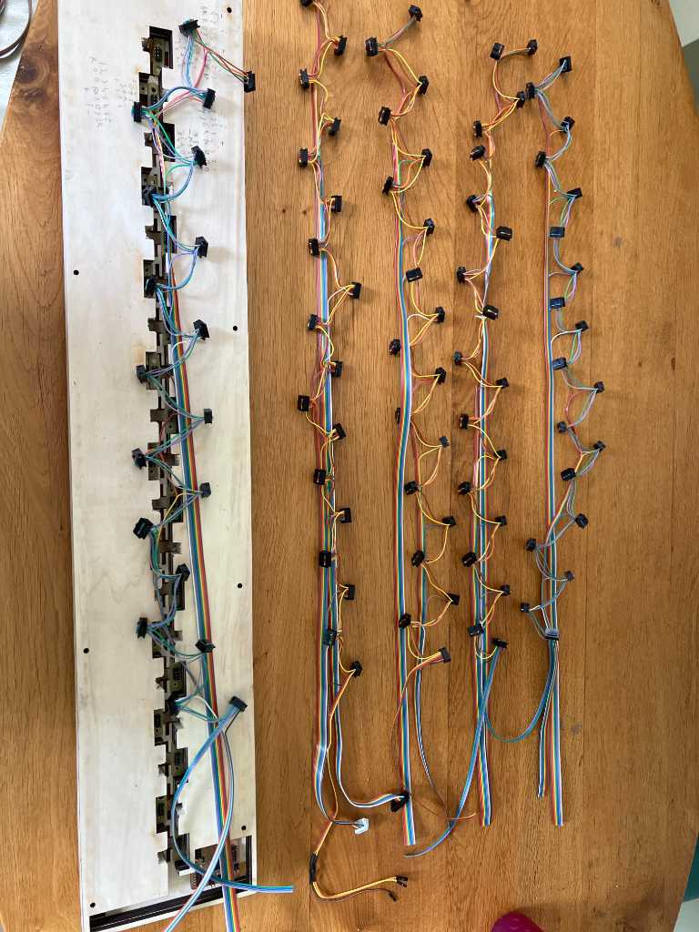
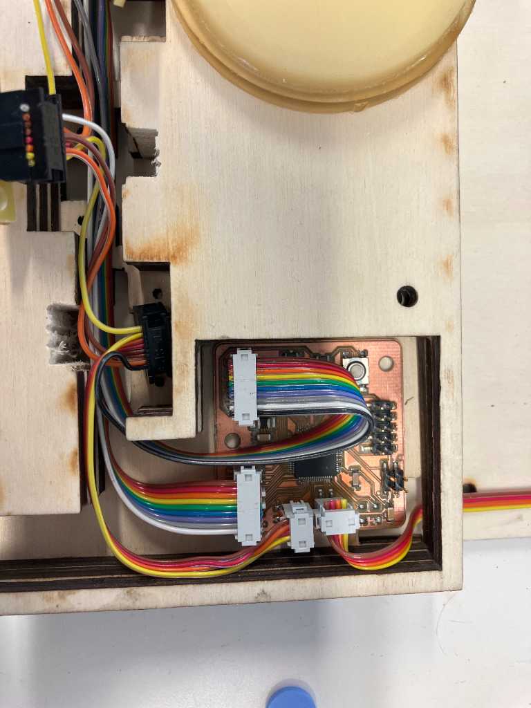
The other side of the cable harness will connect to the sensor PCB using 2 10-pin connectors for the sensor inputs and 1 4-pin connector for power and WS2812B data output.
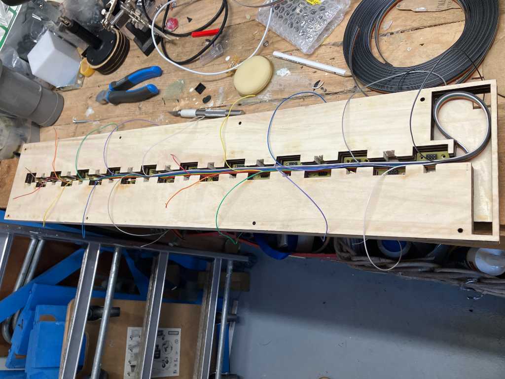
There’s also a 4-pin connector for power and I2C data communication going from the main PCB to each sensor PCB.
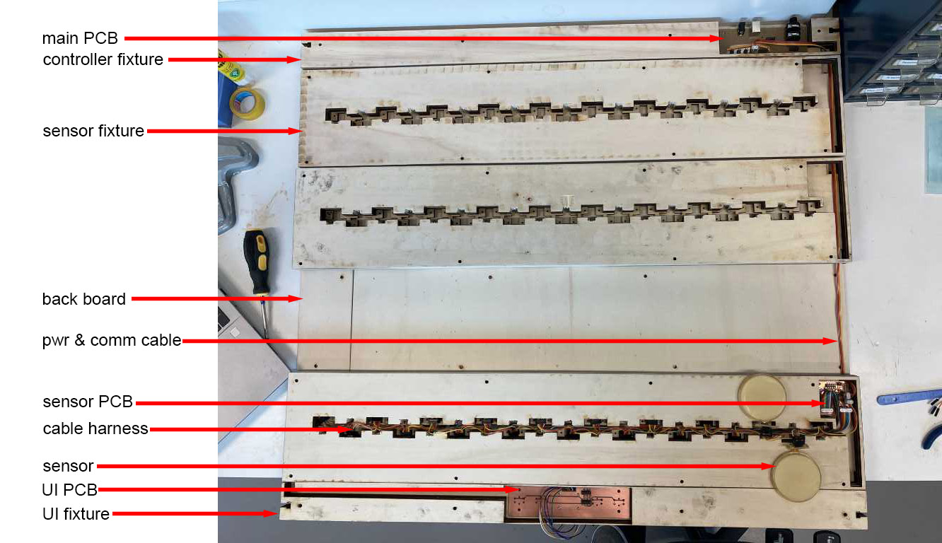
This is the backside of the maribatron (1 sensor fixture is not in the picture), with annotated the different parts.
The final cabling result: