computer-controlled cutting
Topic(s) of this week
- computer-controlled cutting (video, review)
- Demonstrate and describe parametric 2D modelling processes.
- Identify and explain processes involved in using the laser cutter.
- Develop, evaluate and construct a parametric construction kit.
- Identify and explain processes involved in using the vinyl cutter.
Hero shots
Assignments
Group assignment
- Characterize your lasercutter’s focus, power, speed, rate, kerf, joint clearance and types.
- Document your work to the group work page and reflect on your individual page what you learned.
Individual assignment
- Design, lasercut, and document a parametric construction kit, accounting for the lasercutter kerf, which can be assembled in multiple ways.
- Cut something on the vinyl cutter.
What I think I already know
I’ve done quite some lasercutting in the past 2.5 years. I used various materials, know about kerf, etc.
Regarding vinyl cutter I used the Roland Truevis in our fablab a lot as well. This is full-color printer and cutter in one. Hopefully I’ll find a way to use a vinyl cutter and try some other sheets of materials, but I don’t think that will happen this week.
What I want to learn
Vinyl cutter
I want to learn how a vinyl cutter works (see if it’s any different from our Roland Truevis). For my final project It would be great to make my own flex PCB, so I want to try if I can cut:
- copper tape
- Kapton tape
- Dual sided sticky tape
Lasercutter
- I look forward to create the construction kit.
- Maybe I explore a bit more about inlays.
- In Neils’ notes there was a reference to deepnest which seems interesting.
- Use our Epilog Fusion to directly cut DXF by using Autodesk DWG Trueview software (currently we do everything via PDF files and print in Acrobat Viewer).
SSTM planning
Supply
| Day | Supply | Tasks |
|---|---|---|
| Thursday | 08:00-09:30 (train) | |
| 10:00-18:00 | ||
| Friday | 9:00-11:00 (fablab) | how to make almost anything sticker for laptop Try FP molds |
| Saturday | 14:00-17:00 | design individual assignment: vinyl cut |
| Sunday | 14:00-17:00 | design individual assignment: tuQ Compress videos |
| Monday | 10:00-14:00 (fablab) | kerf identification and pressfit test |
| Tuesday | 9:00-17:30 (fablab) | lasercut individual assignment |
| document | ||
| FP? | ||
| Wednesday | 9:00-12:00 (fablab) | document |
| 12:00-13:00 | Local review | |
| 13:00-14:00 | Regional review | |
| 15:00-18:00 | Neil time |
Tasks
- vinyl cut sticker
- More FP molds in white px60
- Engrave mug
- Laser cut accylic 120s
- Click to enlarge photo
Have you answered these questions?
~~Linked to the group assignment page. ~~
- Explained how you created your parametric design.
- Documented how you made your press-fit construction kit.
- Documented how you made something with the vinyl cutter.
- Included your original design files.
- Included hero shots of your results.
- Leave feedback in Nueval that this weekly is ready for evaluation.
WAAG session
Here we go!
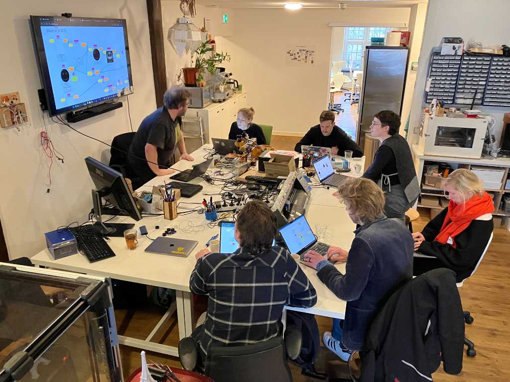
Parametric design
Bas Pijls gave us a workshop on parametric design. We’ve been using magma as quick multi-user sketch tool.
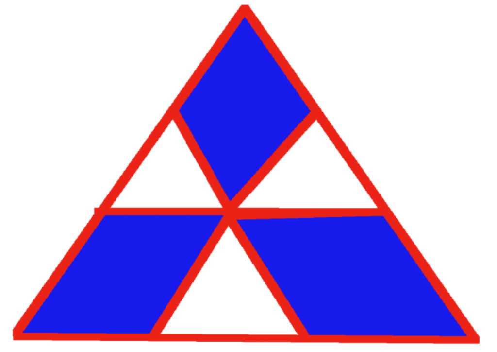
Parametric design is all about expressing shapes using numbers. Like a circle expressed as x, y and diameter. Lots of logos are made out of basic shapes, i.e. the Mitsubishi logo is just 4 triangles:
Bas gave lots of examples, including his own work that he did during Fabacademy. He’s a skilled programmer, so lots of inspiration!
Vinyl cutter
Michelle gave us a workshop on the vinyl cutters.
The roland cutter is driven by Mods. This is a very flexible tool to visually program in a webbrowser. It can also drive various devices straight from your Chromium based webbrowser.
For help: rightclick -> options -> View mods CE project
Programs for all kind of machines are here: rightclick -> programs -> open program.
So we’re going to use this on the Roland GX-24 which is a vinyl cutter available at Fablab WAAG.
Note: On Windows computers, you have to install Zagid Utility to replace the machine driver. See the documentation..
Steps to set up the vinyl cutter:
- Insert the material
- align it as straight as possible
- set the rollers on top of the material
- set the machine to use
piece(type of material) - let the machine auto-detect edges of the matieral
In mods, load an image or SVG and make sure to click calculate in the cut raster block. Then send file.
Quick note on SVG in mods: it will first convert the SVG into raster and then back to vector again. No clue why.
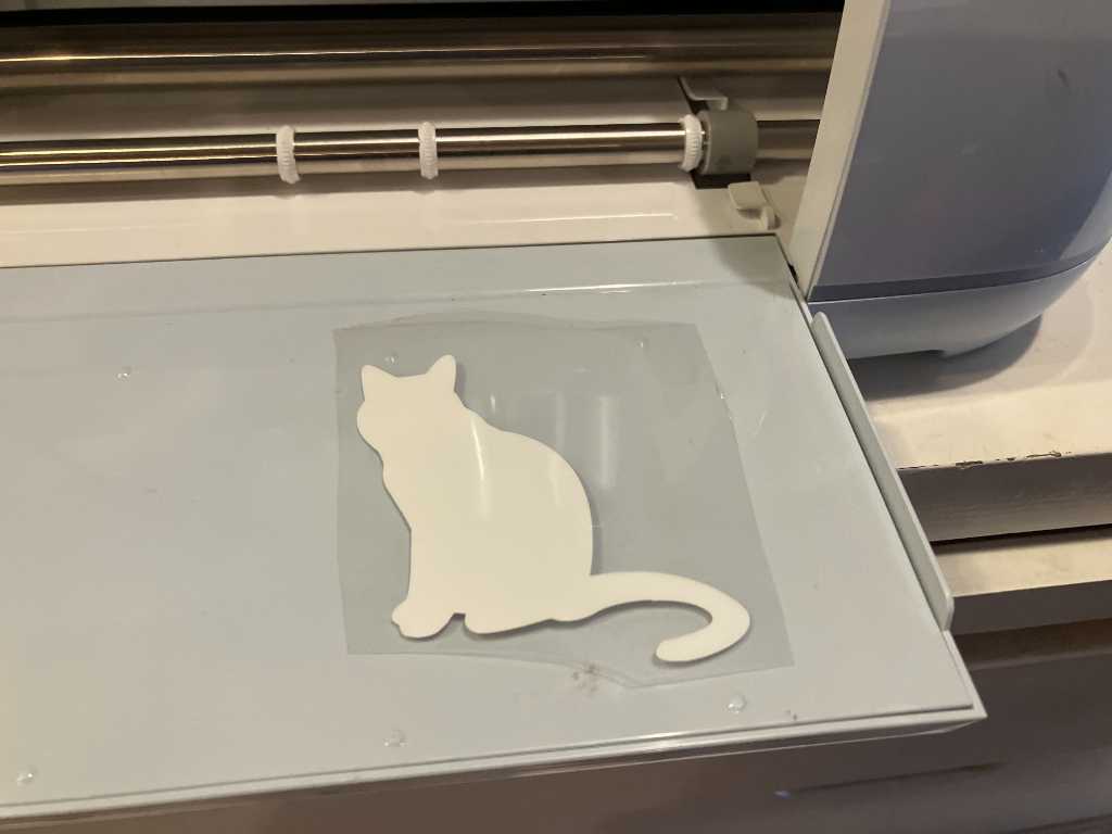
The vinyl cutting result:
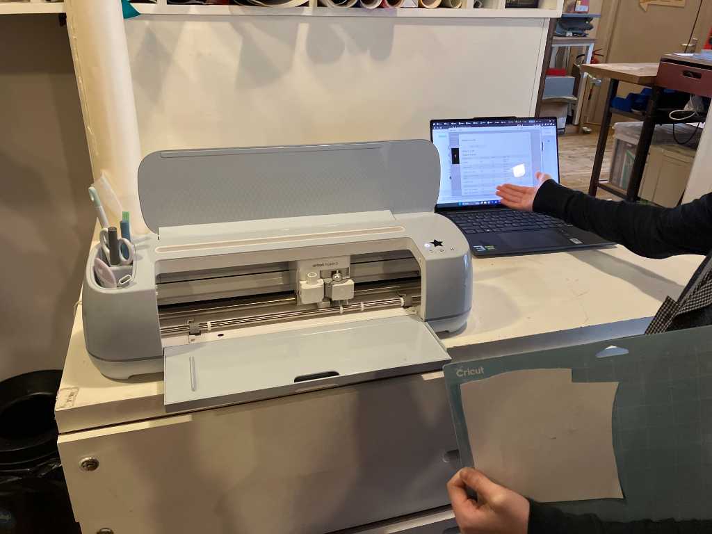
We also tried the Cricut maker 3. The software is very easy. But bloated with popups and sales ads. Also it’s an online kind-of tool. So that doesn’t feel fablab-style to me.
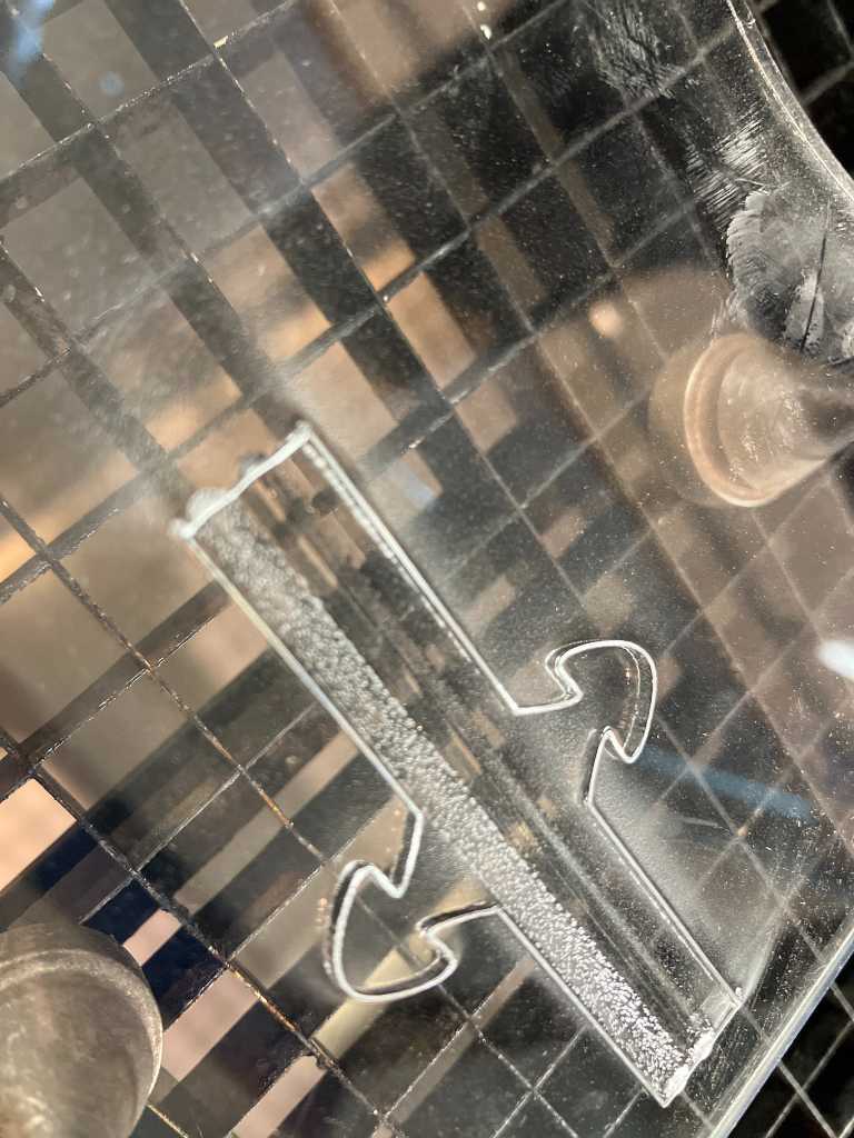
But Cricut hacking is fablab style ;-) This is a defective Cricut that Fablab WAAG tries to revive using open source hardware/software:
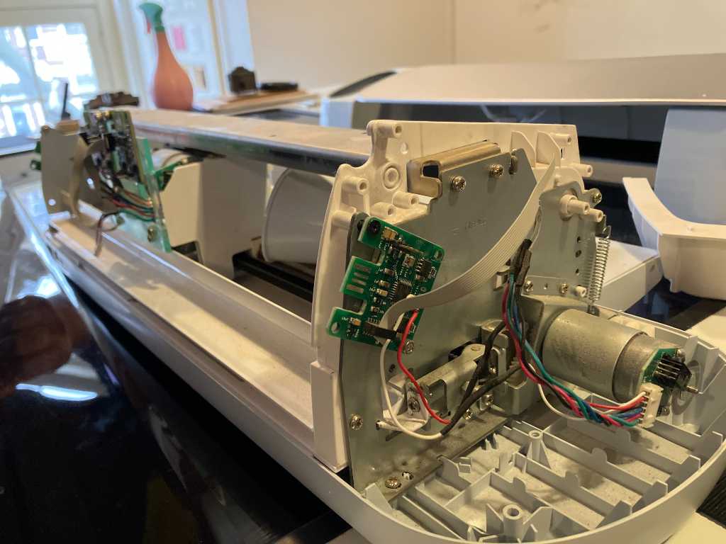
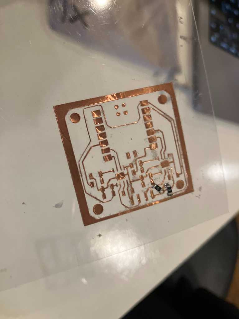
Because Cricut has a driven cutting blade that rotates as it goes, you can actually create nice small cuts. Like this example above from copper tape. So that’s a good thing.
Weeding in vinyl cutting is a thing. A good hint is to use cutting lines in between to aid in weeding. So you don’t have to weed one big piece in one go.
example showing cutting lines from documentation of Bas Pijls
Laser cutting
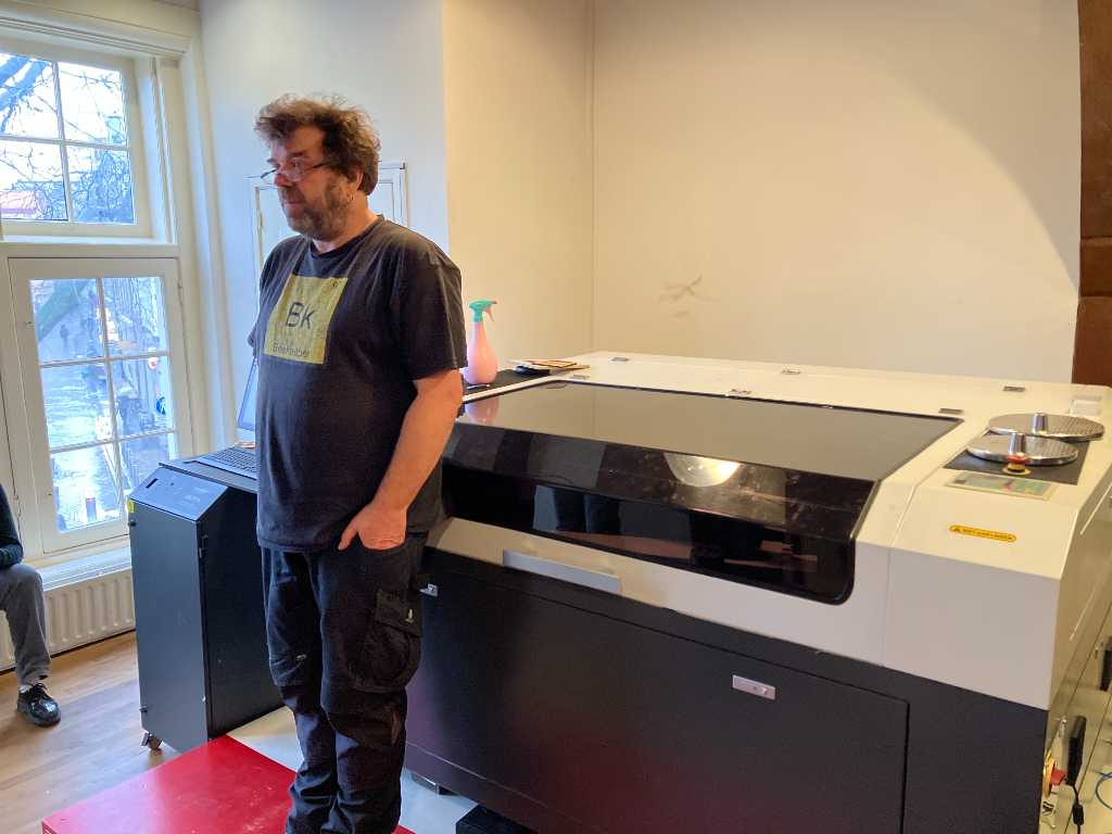
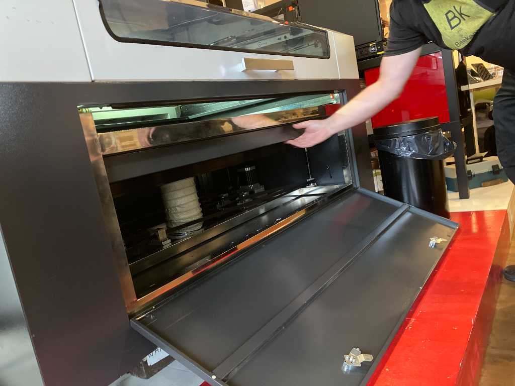
Next we got a workshop on lasercutting. Fablab WAAG just got 7donated a “new” BRM 90130 machine. It’s a 150W CO2 laser with max dimensions 128x85cm.
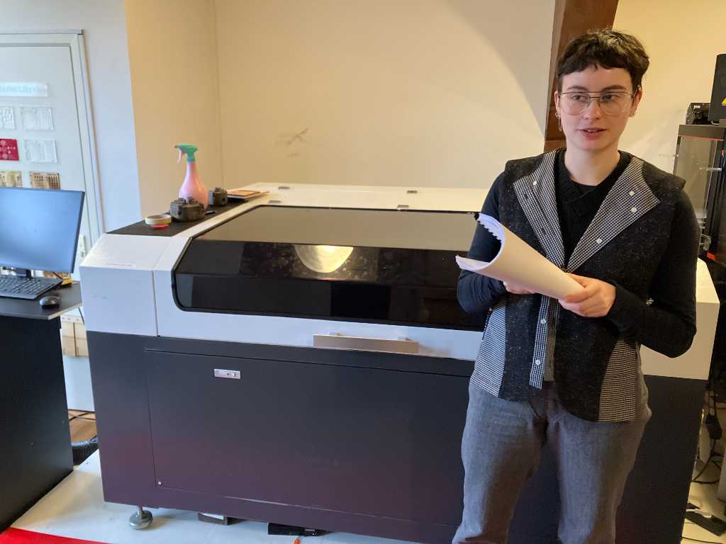
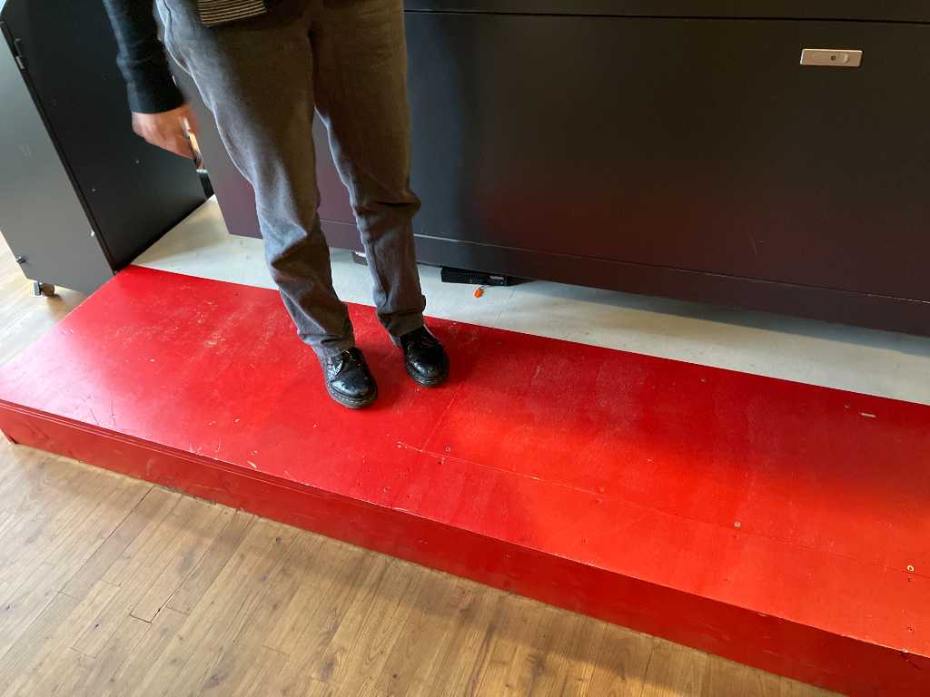
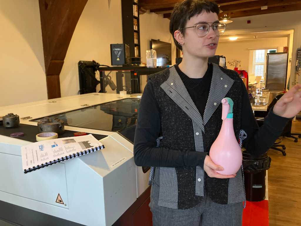
Safety is very importatnt. Never leave the red area on the floor when the machine is in use.
The plant spray unit is to quickly extinguish small fires.
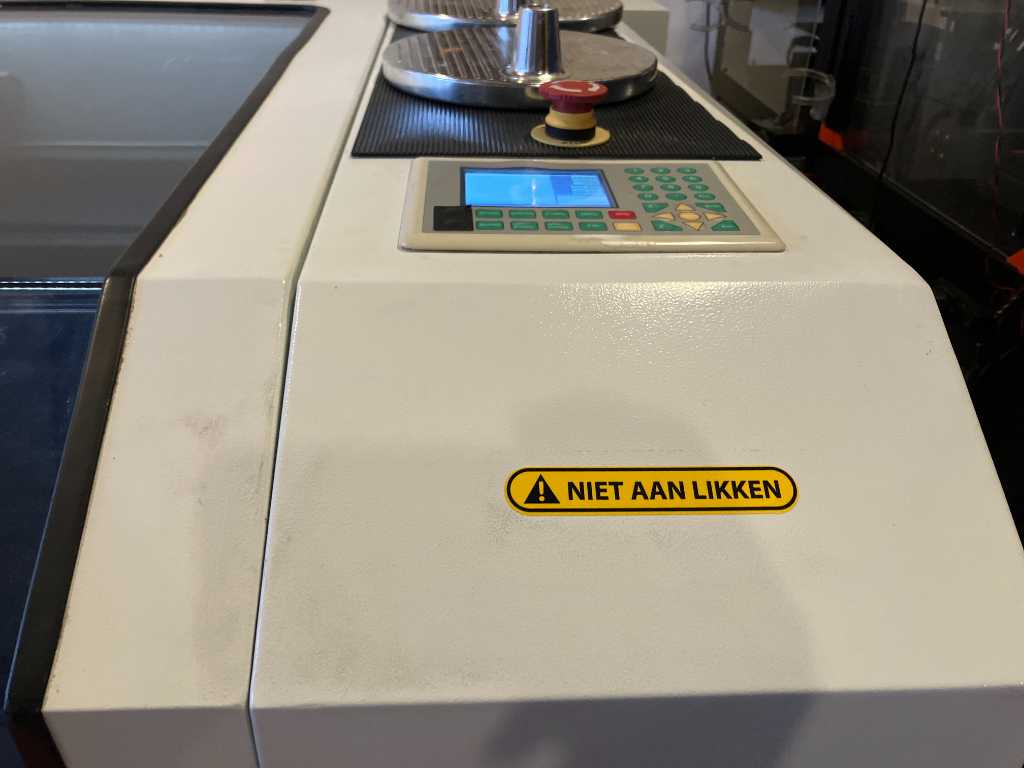
And don’t lick the machine…
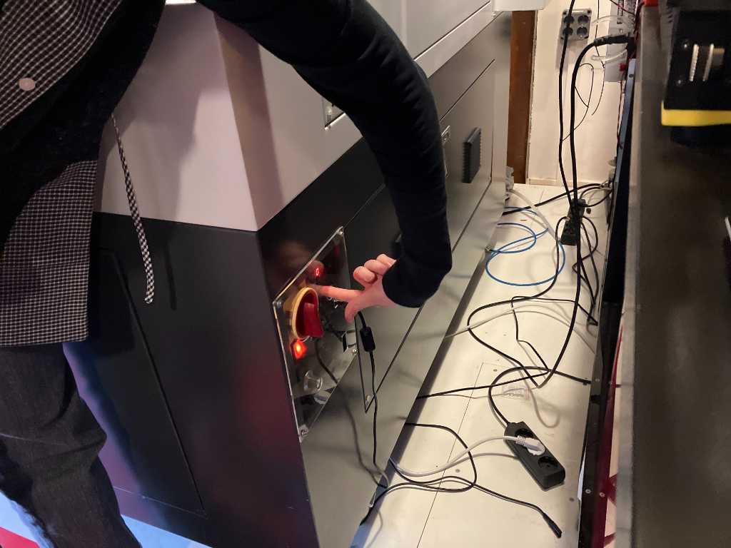
First turn it on using the red button. Then press the reset button. The machine will start homing.
Check if the computer is turned on. It’s below the machine.
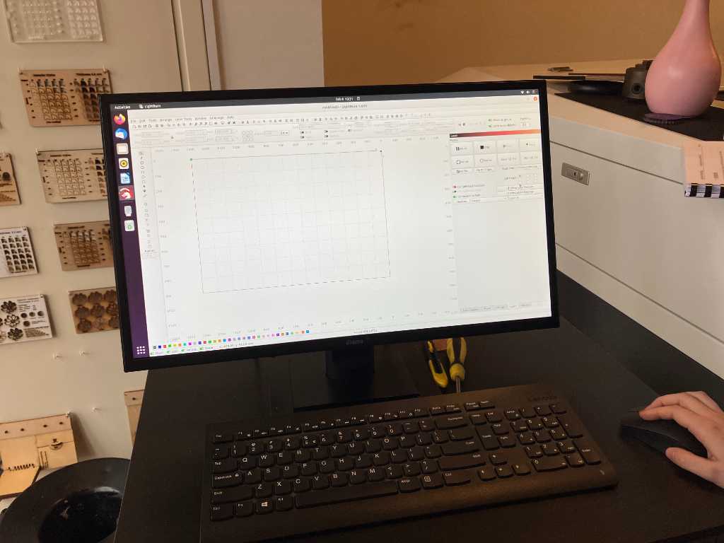
We’re going to use Lightburn software. That’s interesting, because I’ve heard of this software, but never used it because in our Fablab we have proprietary Trotec and Epilog software.
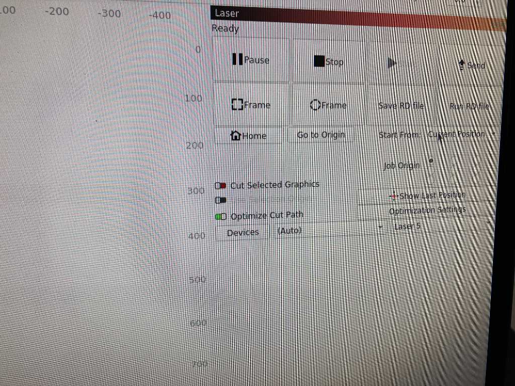
Always make sure that the ‘start from’ setting is set to current position. Never change this! This defines the starting position of the laser.
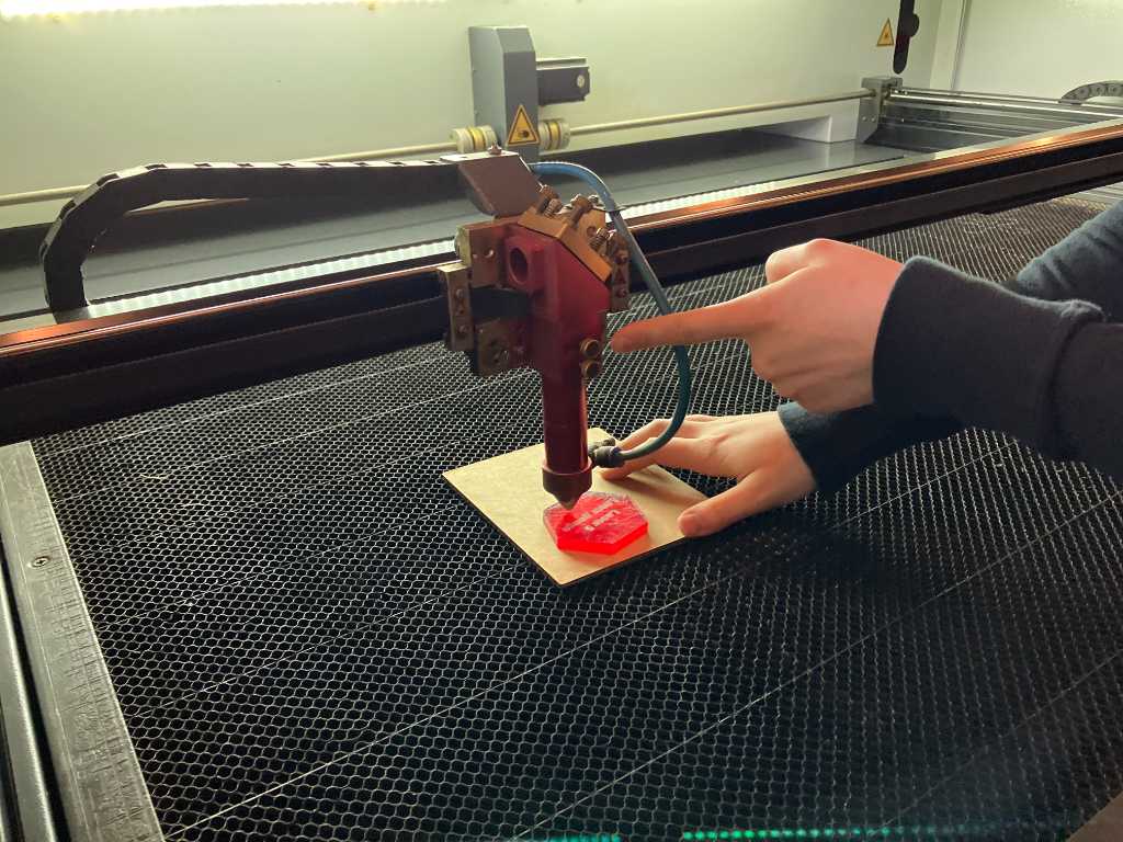
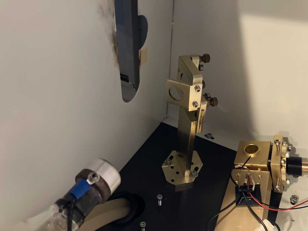
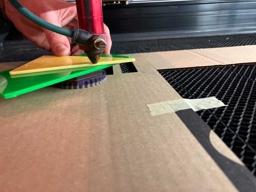
To focus use the focus tool (red piece of acrylic). Unscrew both screws and let the laser head touch the focus block:
In lightburn you can import your design or draw things yourself. Similar to illustrator but not as advanced. You can delete duplicate lines ‘edit -> delete duplicates’.
On the left hand side there are tabs for cuts/layers, move, library, etc. The laser tab is used to operate the laser.
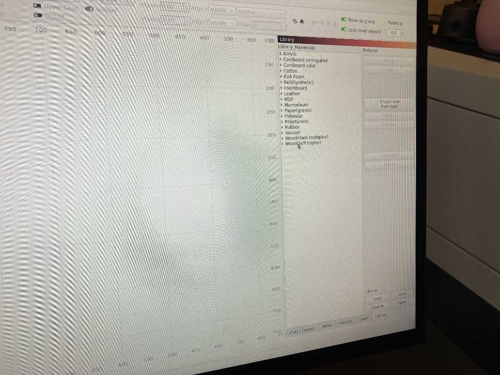
The material library can be found on the left in the library tab. Select a layer, select the preset from the library and click ‘assign’:
Double click on the settings in the layer tab to get more settings, eg number of passes. In this window, Min power and max power is used to compensate for speed reduction in sharp corners.
The laser cutting material library is a good reference. But always check settings with the actual material.
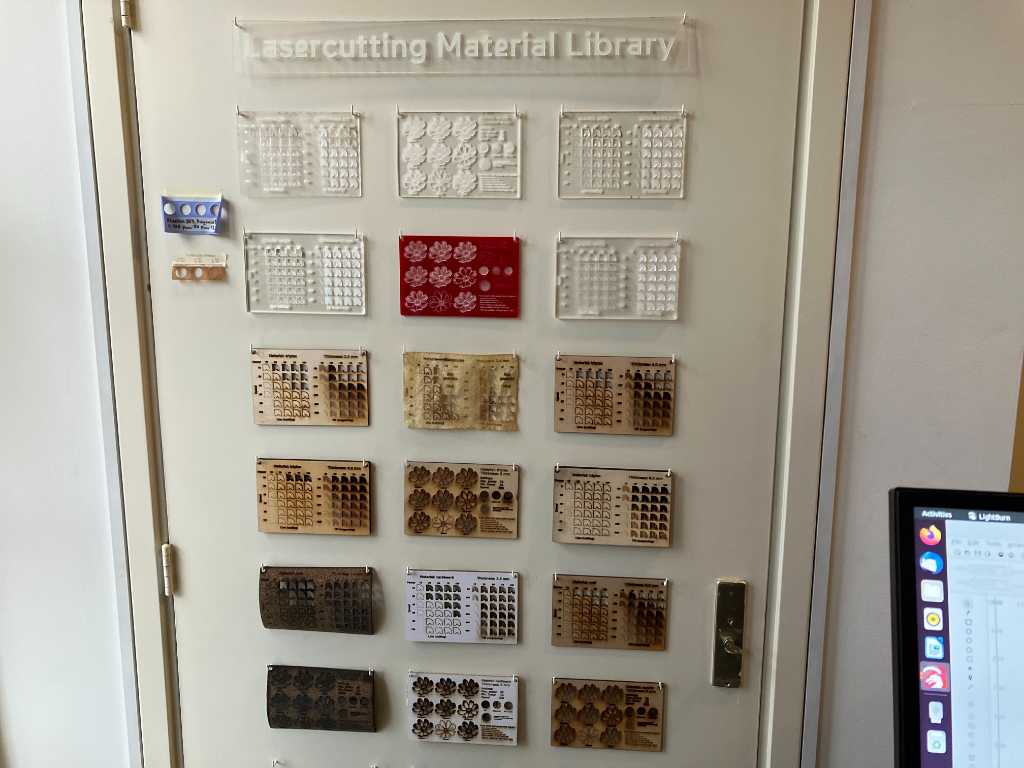
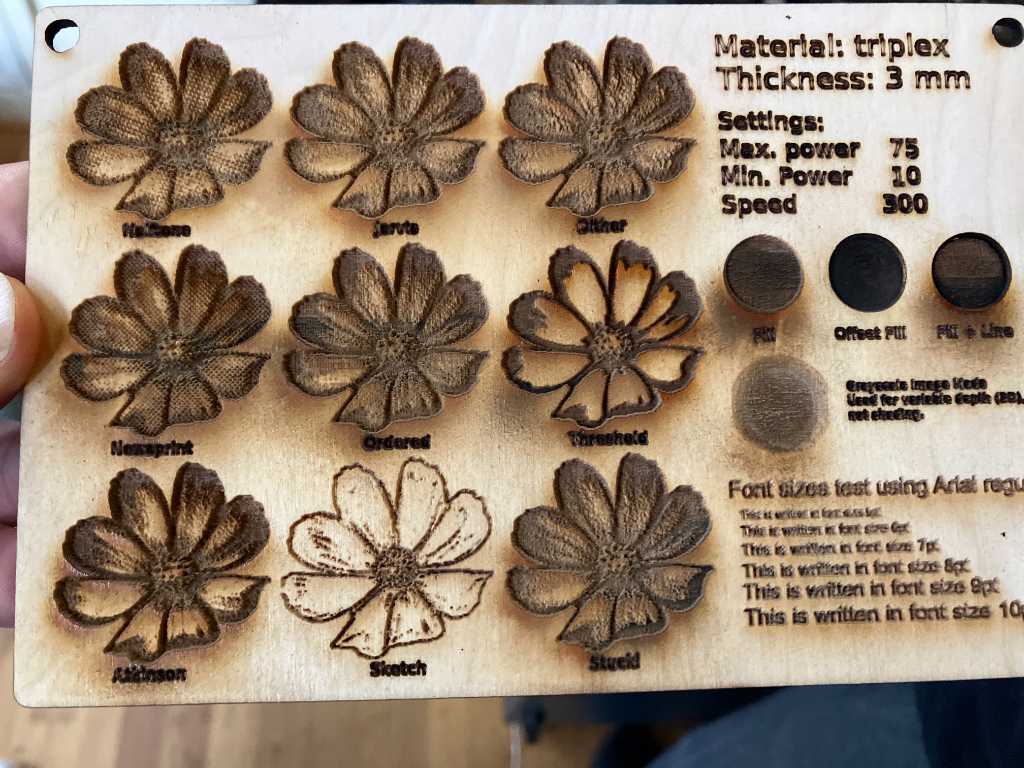
These samples are created using a template created by the ‘material test generator’ in lightburn:
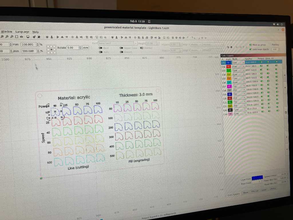
The mode dropdown in the layer tab will define if you’re cutting (line) or engraving (fill). The order of the layers is going to be the order of processing of the machine.
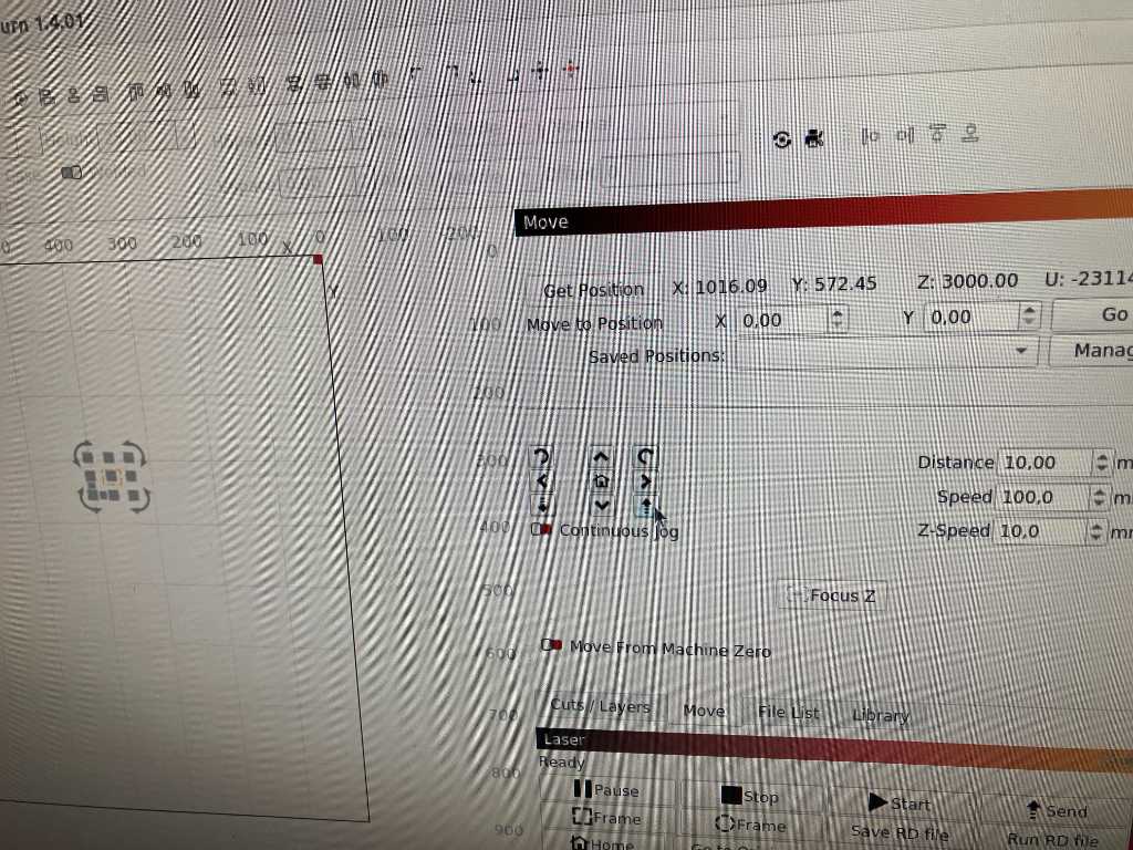
The green dot is the starting position. Because you always use ‘current position’ the green dot equals the current position of the laser head.
If you want to be certain where it’s going to cut, use the ‘Frame’ button. The machine will trace without actually cut.
Near accident #fail: watch out with using these buttons to move the last head. The z-axis is really close to the X and y move buttons! So during the workshop we almost crashed the head into the work bed…
Next, load the material and make sure it’s flat. If not then tape it to the workbed.
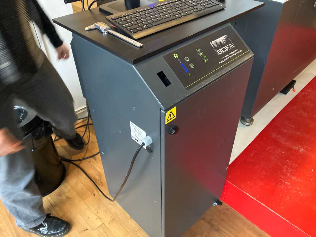
Before starting to cut first plug in the fume extraction system!
Don’t open the lid immediately after cutting. Prevent any fumes escaping because they’re toxic.
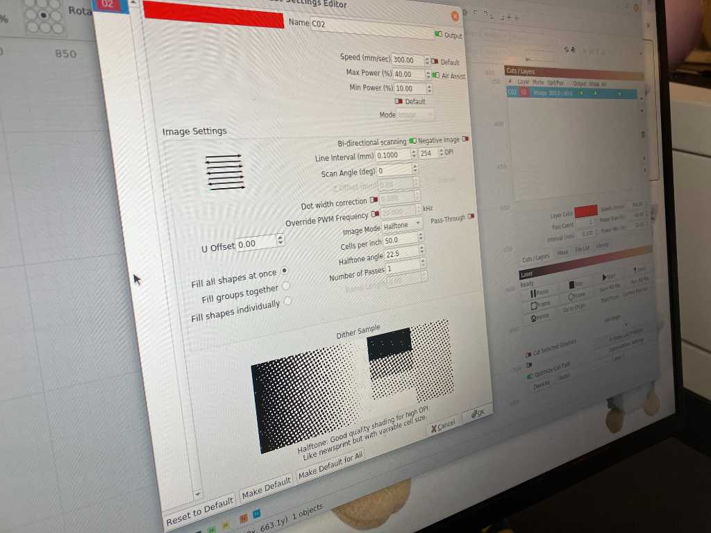
Lightburn can interpret images in different ways. E.g. halftone, Jarvis, stucki. They all produce different results.
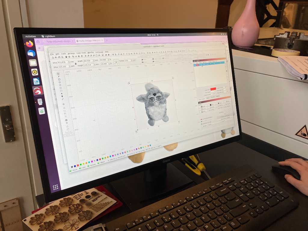
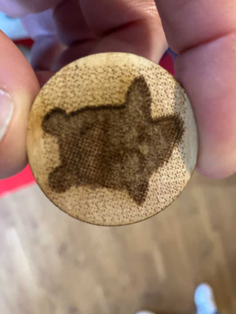
Let’s try engraving a furby. You’ll immediately see that when importing an image it pops up in image mode. Double click again to open image settings. Here you can define line intervals, image mode, etc.
Way more smoke if you’re engraving.
Who’s the real Furby?
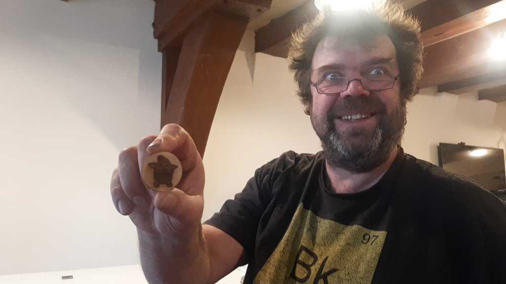
Settings need a bit more tweaking ;-)
technical workshop lasermachine
Henk gave us a workshop on the technicalities of the lasermachine.
Machines are stupid #henkquote
There’s a CO2 laser tube on the back side. Mirrors reflect the laser to your working material.
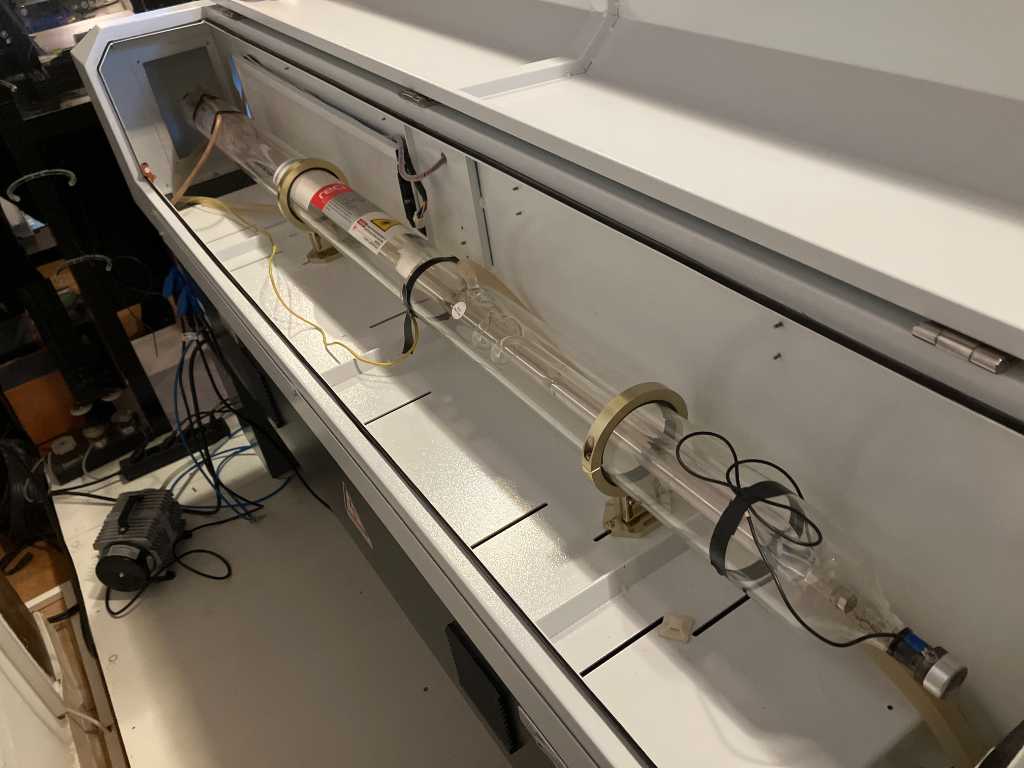
This machine has an air compressor inside. Turns on with the machine. This is for the air assist.
There’s also water cooling to cool the lasertube. Again that’s switches on automatically with the machine as wel.
The mirrors and lens will need to be cleaned every once in a while. At fablab WAAG this is done once a week. Also below the table it should be cleaned.
Group assignment
as instructed we’re not going to document on a separate group assignment page, but in this section.
We’ve split up the group assignment. Here are the other groupmembers docs:
Kerf test
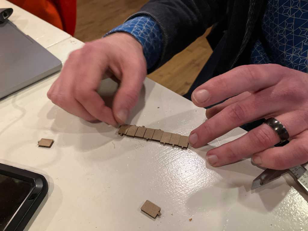
Vera created a Fusion file with 10 small blocks of 10mm width:
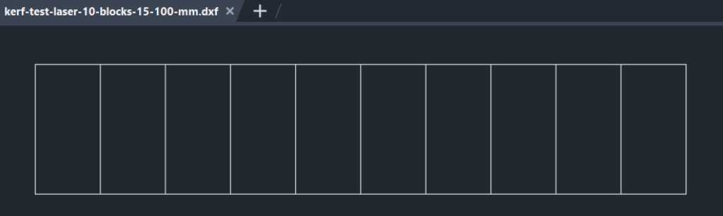
We cut these using the BRM lasercutter:
To get the right settings, we tried various power setting: 55, 40, 30 and 20%.
Best Settings we found:
Speed 35%
Power 30%
So 10 blocks with designed width of 10mm result in a total actual width of 95,83mm.
So this is 20 * 0.5 kerf = 10 * kerf. So (100mm - 95.83mm) / 10 = 0.417mm.
We actually think this is a really large kerf. We question if the laser is correctly configured for the supplied focal tool.
Pressfit test
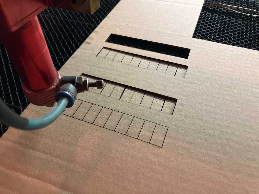
I created a pressfit comb, parametrically. Unfortunately we didn’t have the change to cut it, but I’ll try this in my fablab coming week.
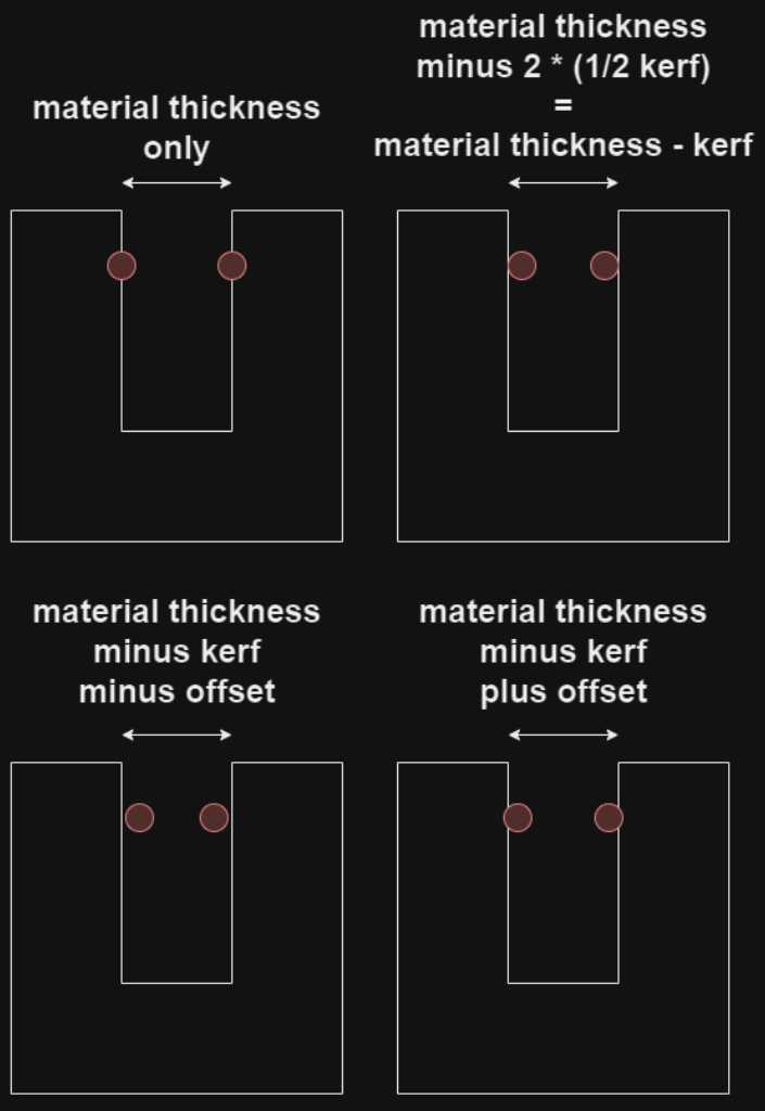
This is the theory of my parametric design. This schematic shows topview of material. Red circle is the laser.
Here I created the pressfit comb tester in Fusion using parameters.
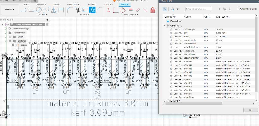
The resulting sketch can be saved to DXF (rightclick the sketch and ‘save as DXF’).
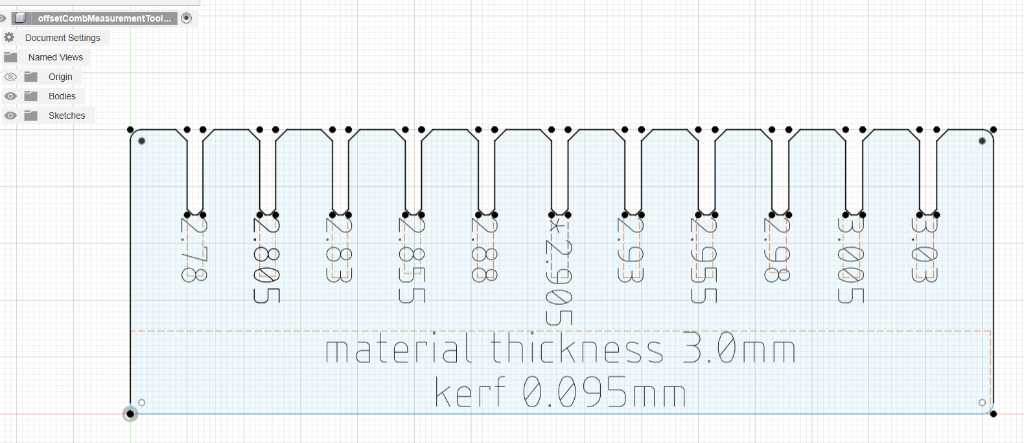
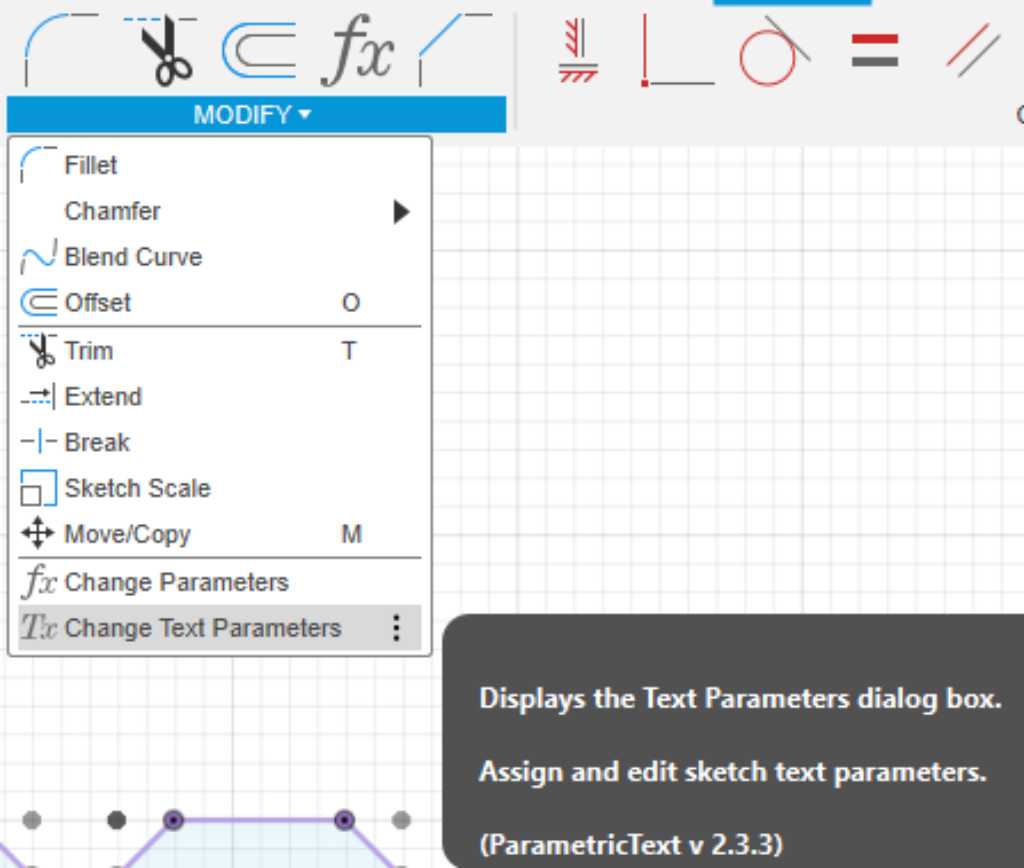
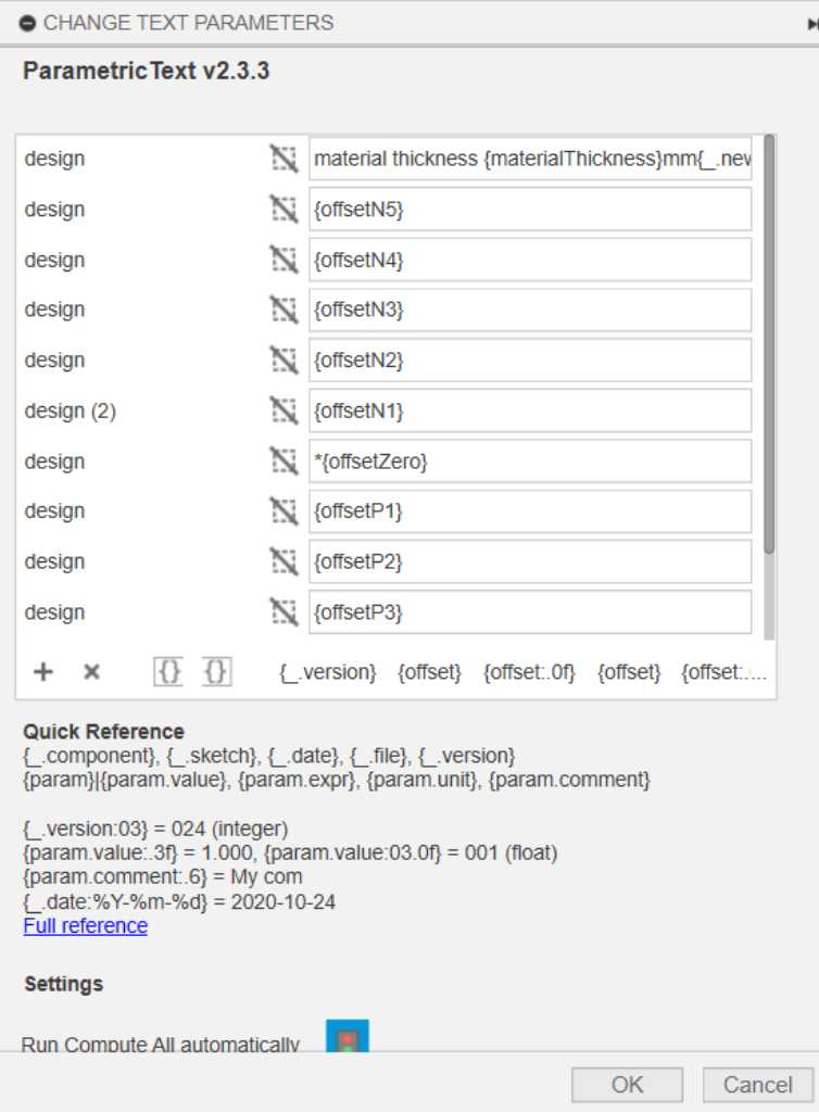
I wanted to engrave the offset values on it but didn’t want to manually type it in. So I used a Fusion addin called ParametricText. The documentation can be found here.
The addin creates an extra element in the modify menu called “Change text parameters”:
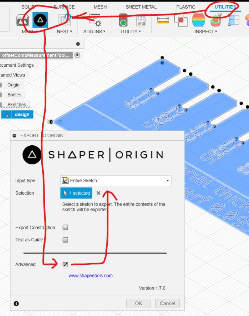
Unfortunately when saving this sketch as DXF, Fusion also exports all construction lines. I looked this up on the internet and this is a frustration to everybody. A 5 year old post on reddit pointed me to an addin from shaper tools and that works perfect! It creates a Shaper icon in the Utilities tab. Click this, select ‘advanced’ and use ‘entire sketch’ as ‘input type’. Now you can select the sketch and it outputs an SVG without construction lines in a folder of your choosing.
Importing this into Illustrator does nice! In our fablab this is interesting, because we can separate laser processing based on colors. That makes life easy.
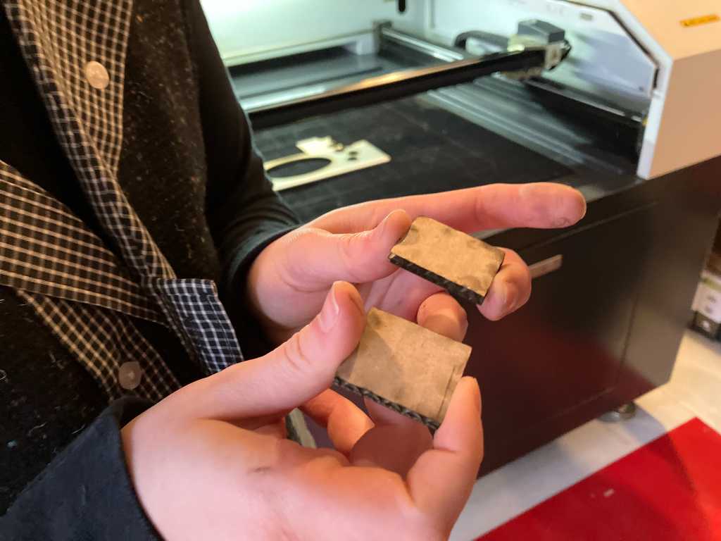
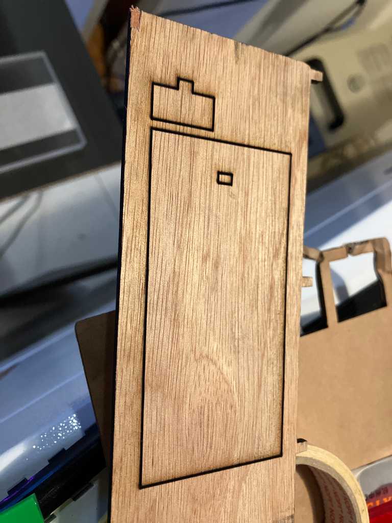
Focus test
So Edwin quickly folded a laser focus test tool from cardboard. At the same time Vera and I made a similar one in Fusion:
Did it work?
Well, the lines are all much too wide.
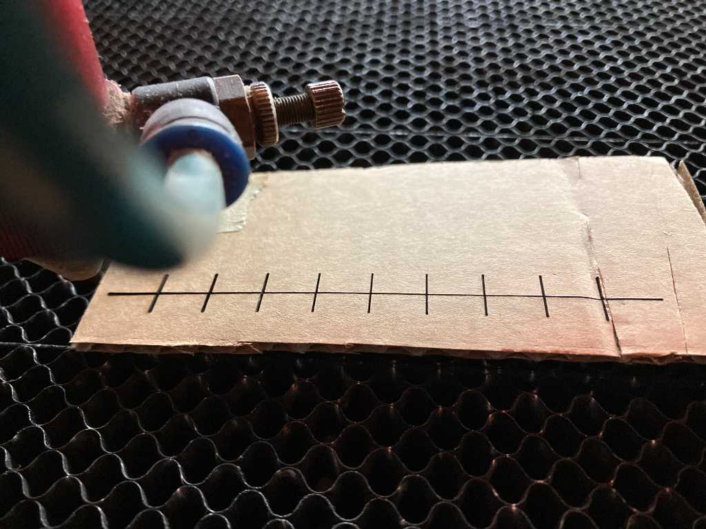
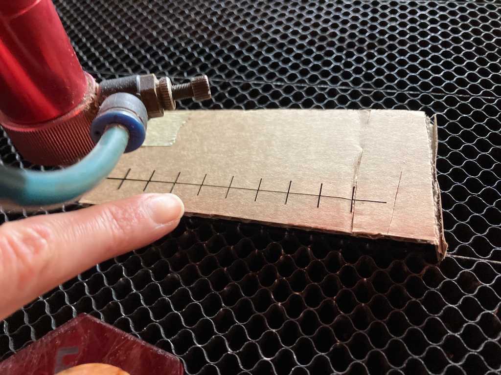
Although this is the smallest cut, it’s not good.
Troubleshooting
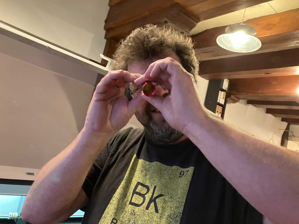
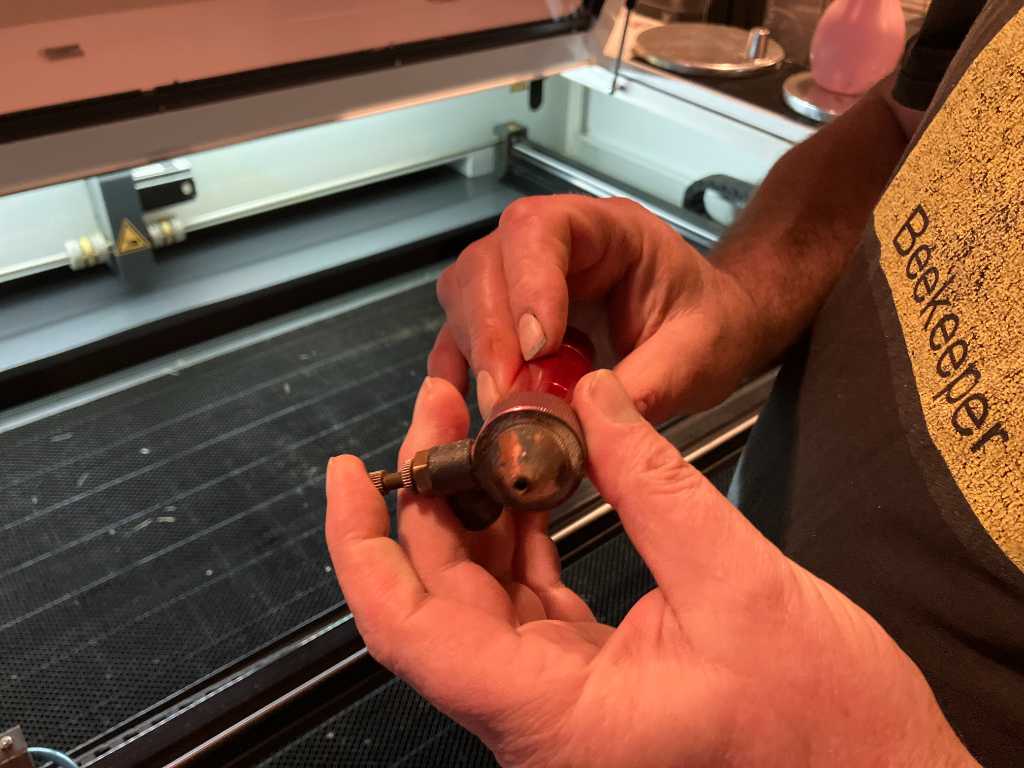
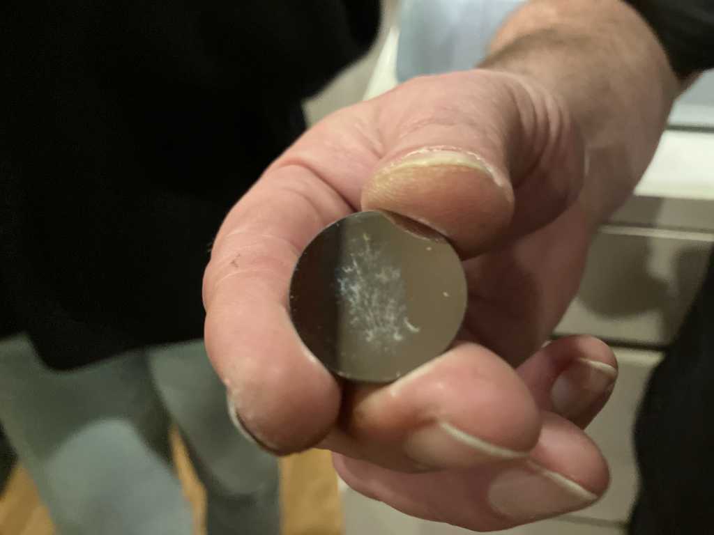
So let’s take it apart.
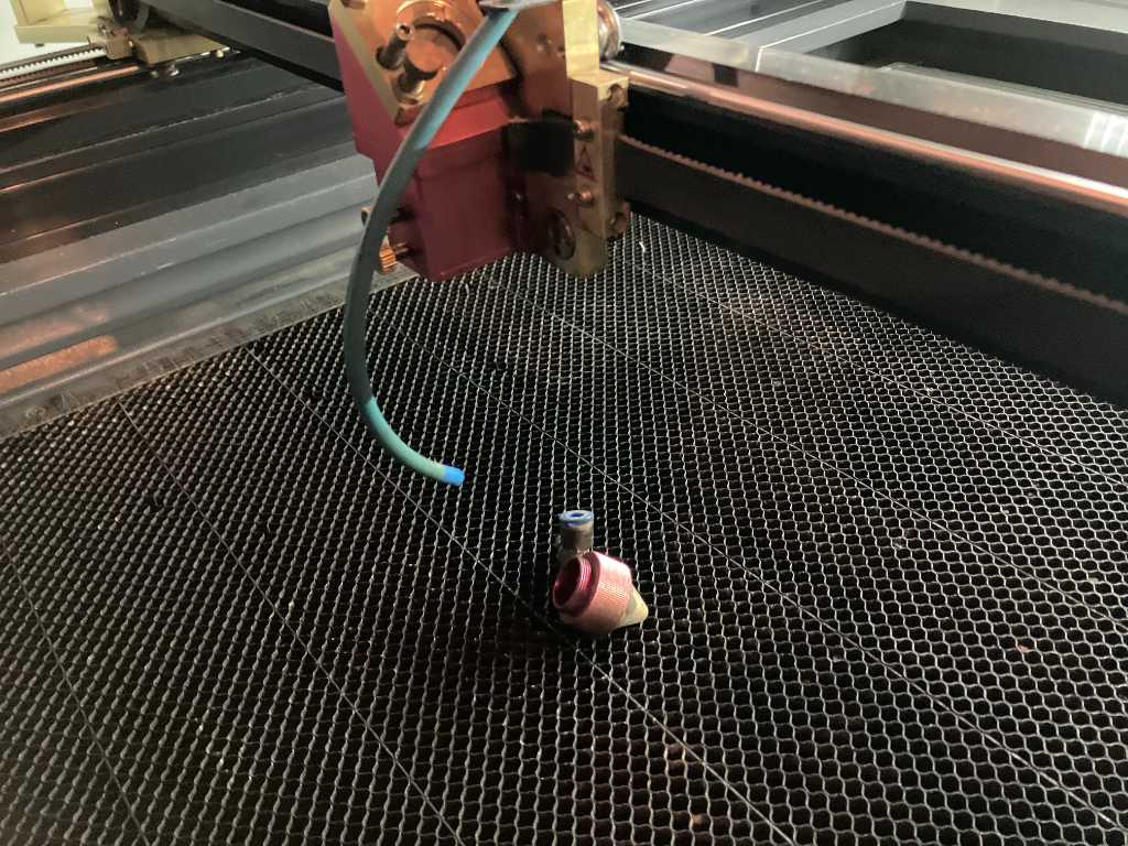
The lens is dirty. #fail
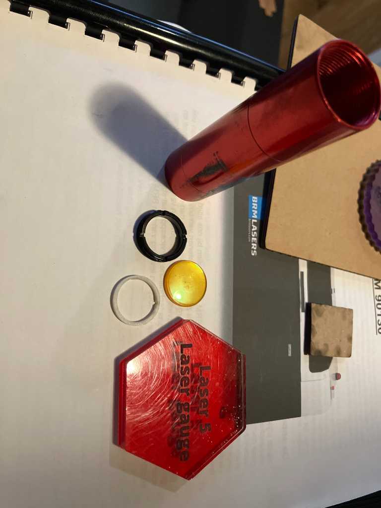
The lens assembly consists of the red aluminum tube, the actual lens itself (yellow), a white spacer and a black nut that keeps the lens in place. The red piece of acrylic is the lens focus tool.
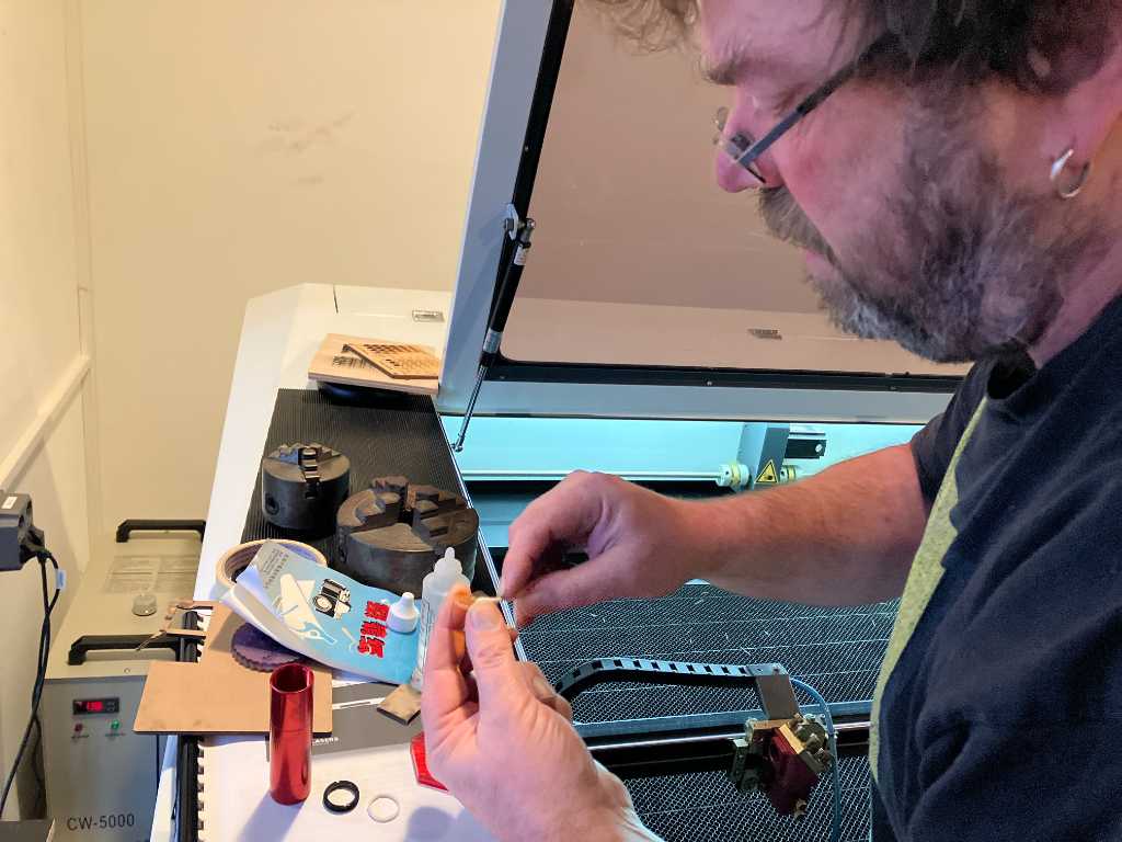
But now it gets interesting. It doesn’t seem that the dirty lens is the only issue. Troubleshooting time: Henk has the idea that the focus distance is incorrect as well. From my experience with machines of different brands, the focus distance should be much larger as well. Does depend on the lens obviously, but still.
So Henk swapped sides of the tube that holds the lens. The lens can be placed on two sides where the distance between lens and workbed if different. So maybe this was wrong?
Tried the focus test again after reseating the lens:
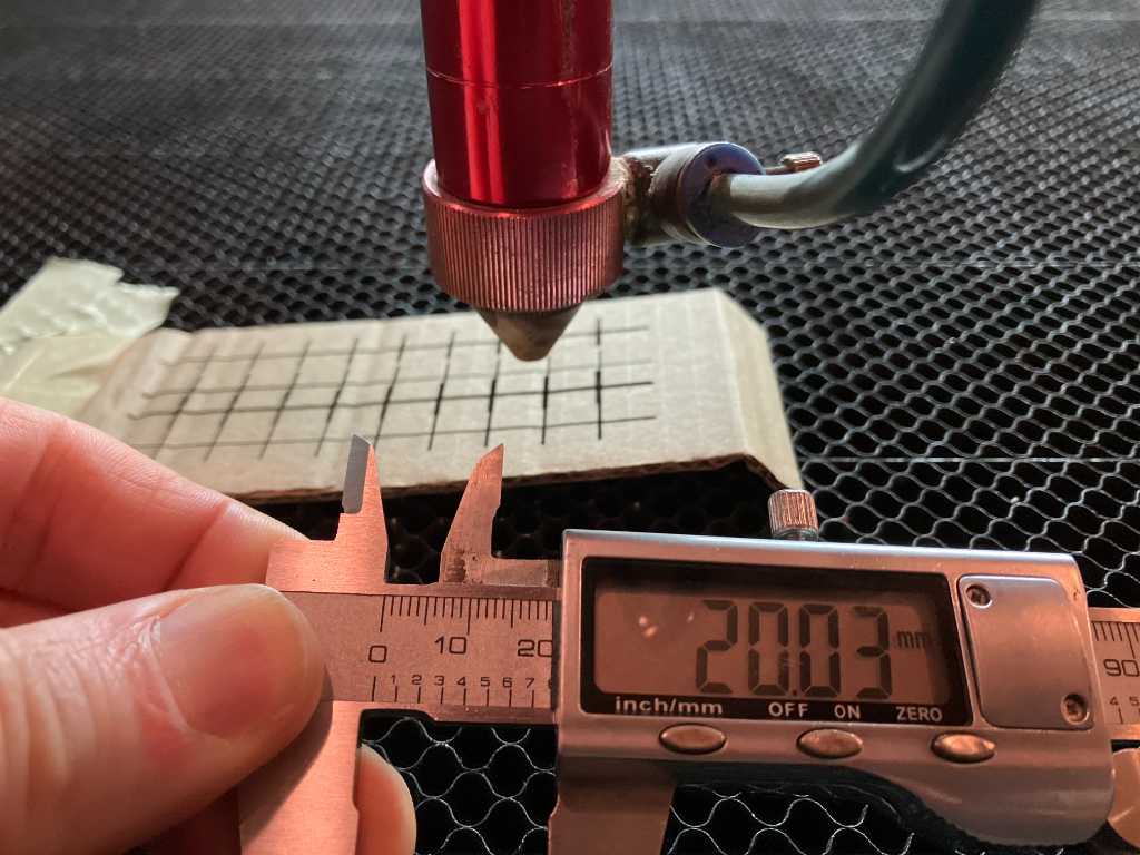
Best focal distance is 20mm lens-to-material. But we don’t have a focus tool that is this exact. No worries:
New kerf test:
We now have 96.98mm. So with this test, the kerf is 0.3mm. Better, but still quite large. Let’s do another focus test. This time with our fusion designed model.
And now we run into biiiig issues. The laser doesn’t even cut through 3mm of plywood. Something really bad is going on :-(
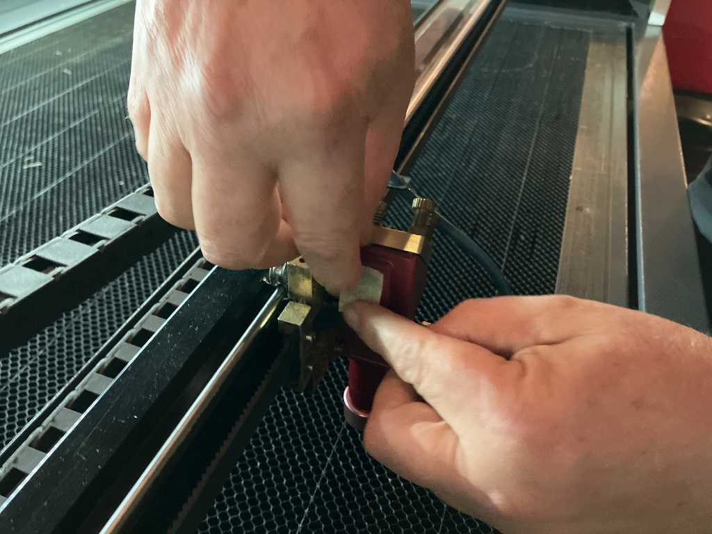
After more troubleshooting we find out that the tube becomes hot! That’s a wrong signal. This should never ever happen. Maybe the mirror(s) need alignment?
So we’re going to test mirror alignment with an piece of tape. We’re going to shoot a short burst of laser energy. If mirrors are aligned properly, the laser should hit the center of the circular hole exactly:
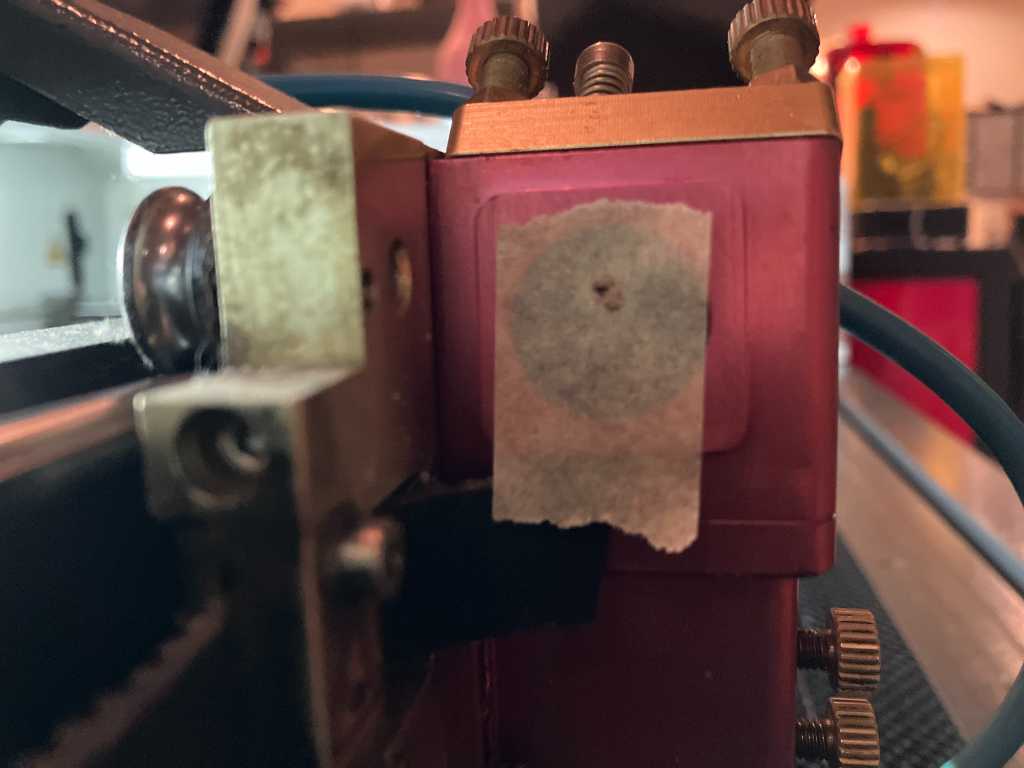
But no. It’s way off. After spending lots of time on aligning the mirror, it still wasn’t very good. Last troubleshooting step found another error: Dirty mirrors:
So that were many issues that all accounted for a single outcome: No proper lasercuts for us today. But the tools we made did allow us to discover there was something seriously wrong. The troubleshooting started because of the kerf that didn’t give expected results. Next our focus test confirmed something was wrong.
In the very last minutes of our day at WAAG, fellow student Joe was able to lasercut a working pressfit comb. Time to call it a day and have a drink!
Link to repo
Individual assignment
Vinyl cutting
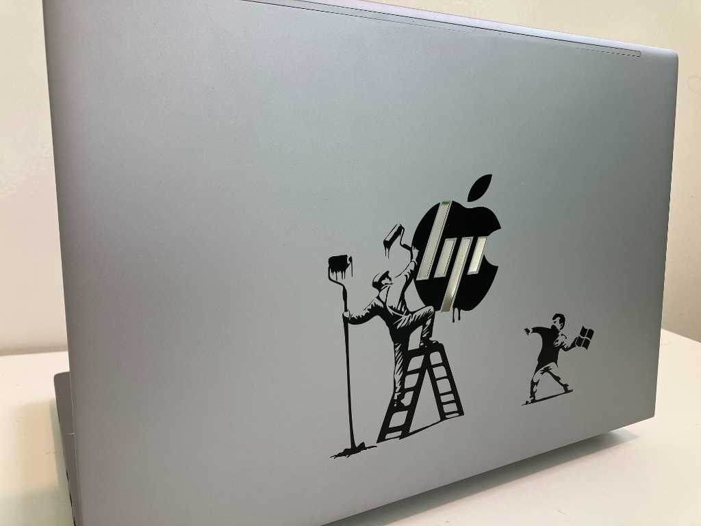
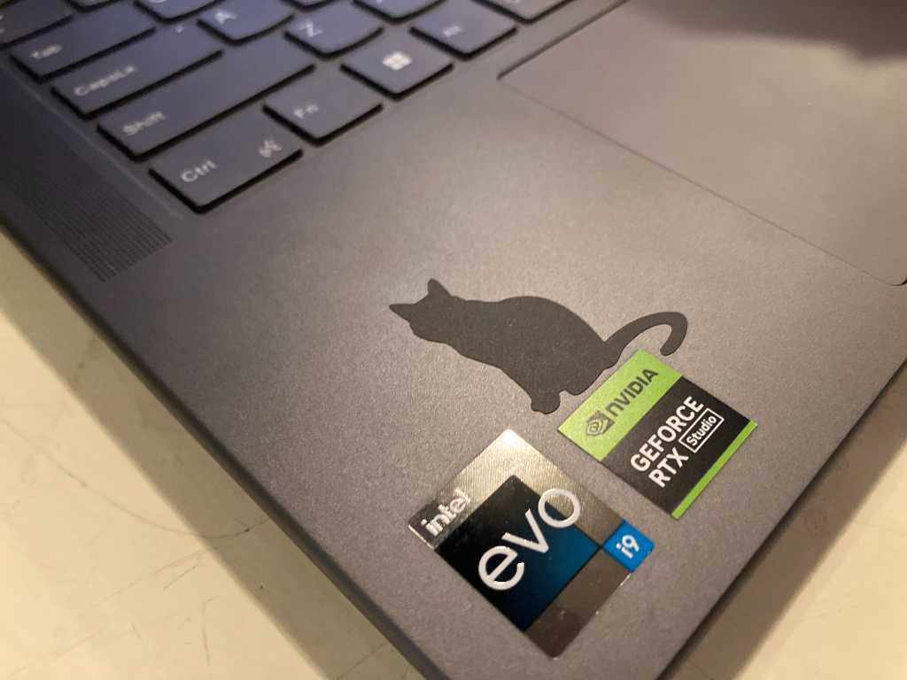
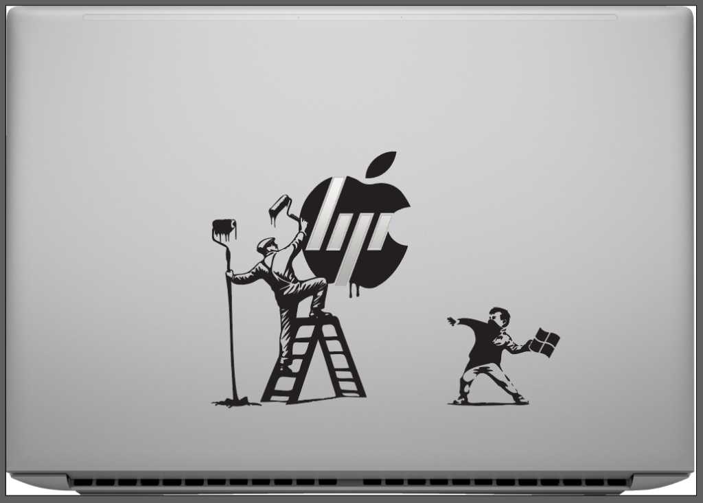
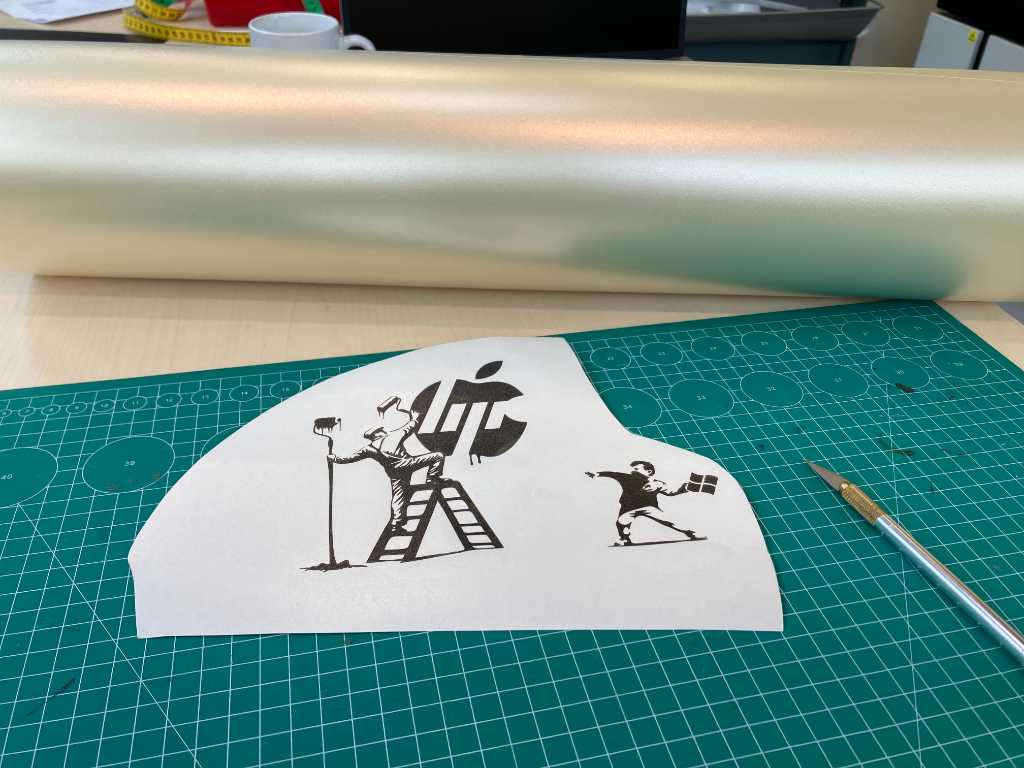
A custom sticker on your laptop proofs you’re part of the lucky few. I was given an HP laptop by my University. Although I’ve been using Macbooks for over 15 years, I had no saying in this. So let’s make some humor out of it.
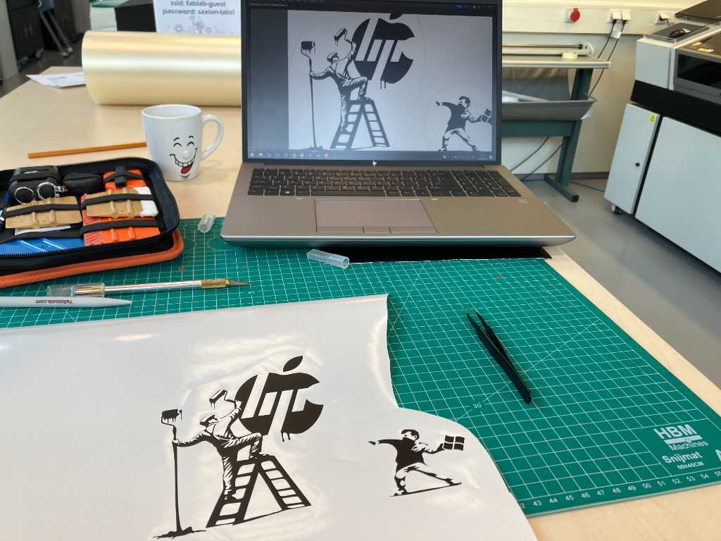
I had Copilot AI design some images of what I wanted to do.


Copilot AI: create a black and white drawing in the style of Bansky where there is a painter on a ladder holding a paint roller, painting the hp logo. the Painter is out of balance and almost falls of his ladder because a little boy throws an apple at him. the apple is in the style of the apple logo
and
a black and white image in the style of bansky of a little boy throwing rocks
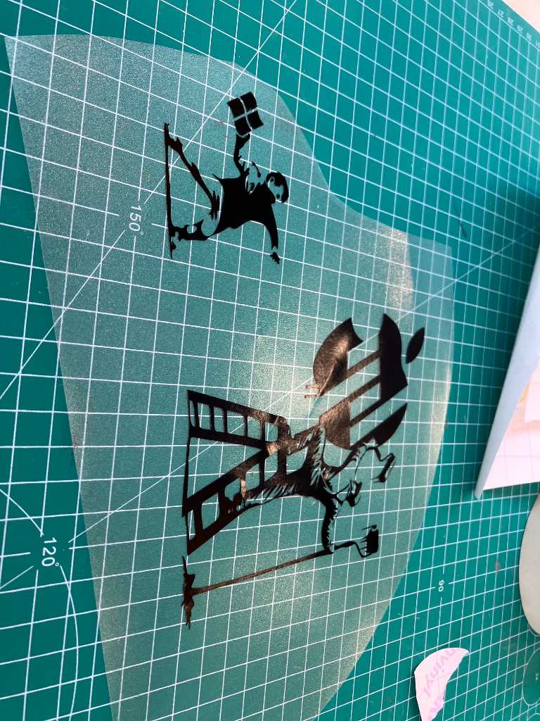
Next I found a high-res picture of the lid of my laptop that helped to get the right dimensions and I found an SVG of the Windows logo. I combined all these elements in Illustrator, worked hard on it, and this is what came out
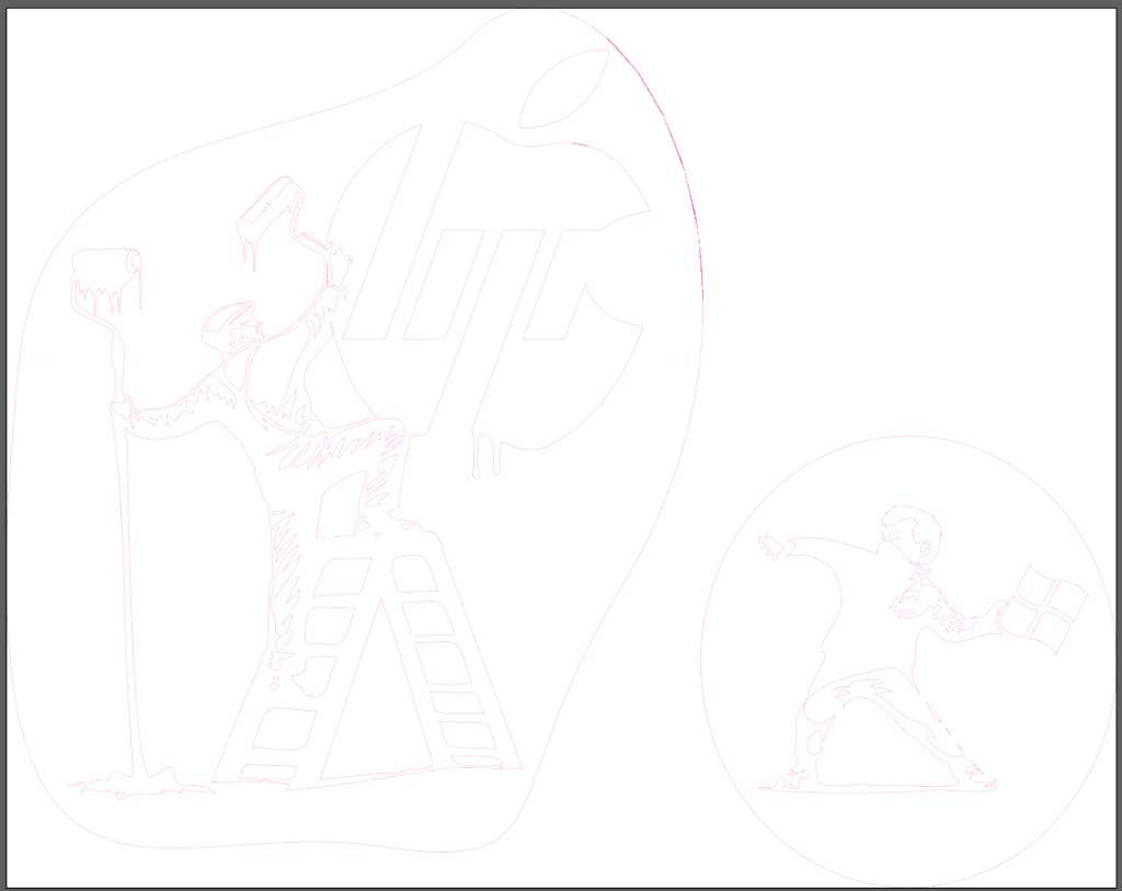
I converted the outlines to the specific swatch color and name that is required to cut using the Roland Truevis print-and-cut machine that we have in our fablab. Based on Bas’ advice I also places a shape surrounding the image to aid with weeding later on.
I’m using black vinyl that we have in the Fablab. Although our Roland Truevis print&cut machine can also do full color prints, I wanted real black. And black vinyl is always more black than printed black.
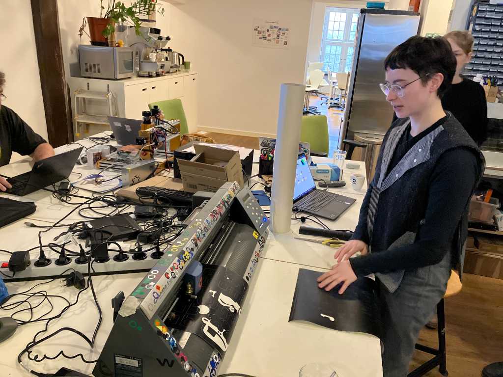
A picture of our print&cut machine is below. On the left various rolls of vinyl, stickermaterial and other foils.
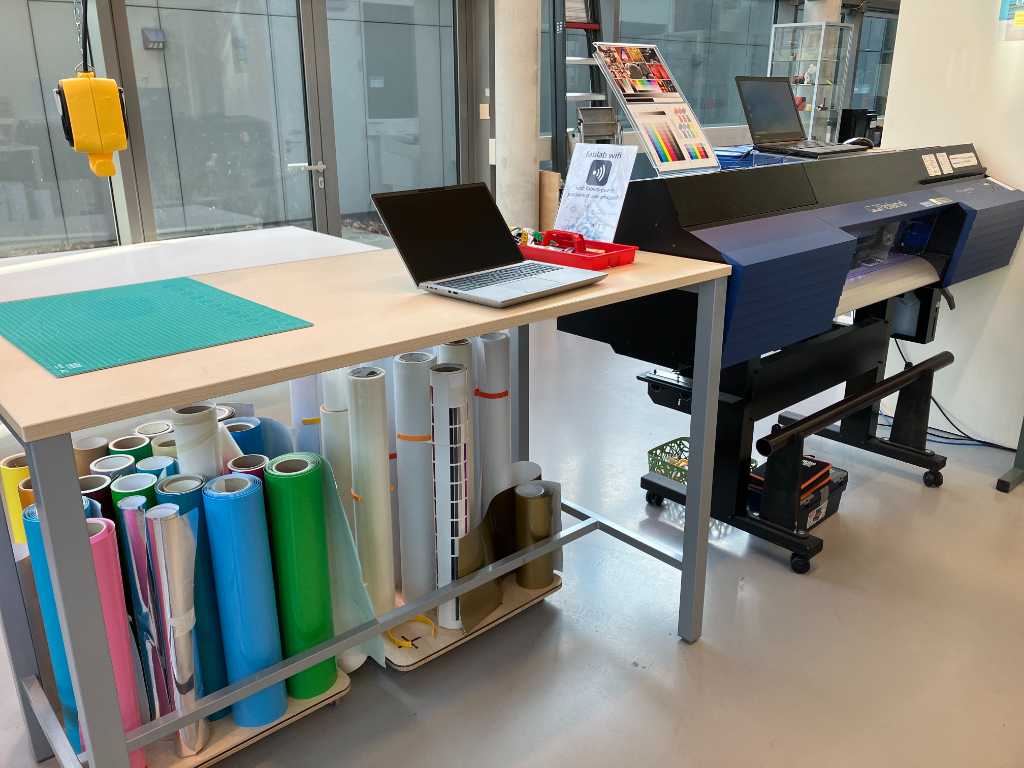
First thing to do is check the cutting power. The Roland can create cutsamples. I tried a few, had to replace the cutting knive as it wasn’t sharp anymore and eventually ended up with a force of 70gf (grams force).
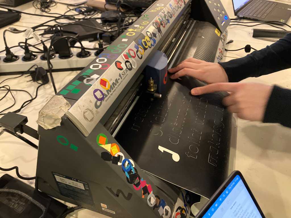
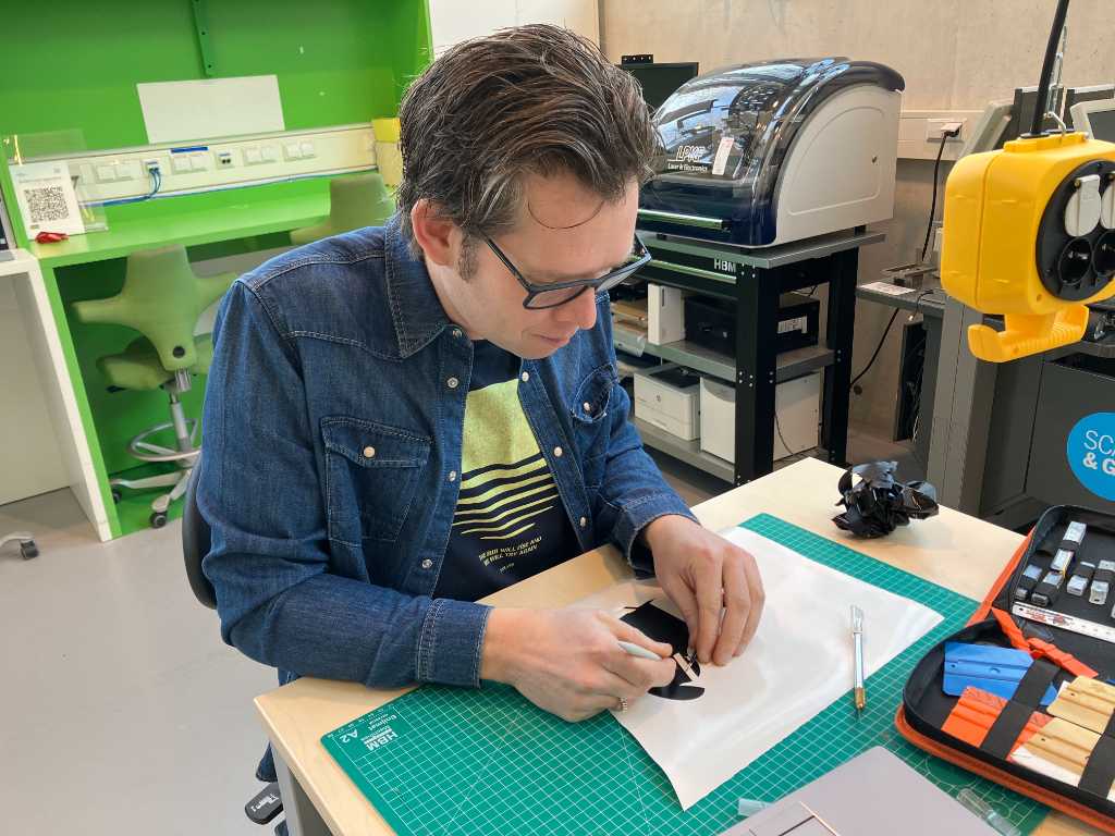
The machine in action:
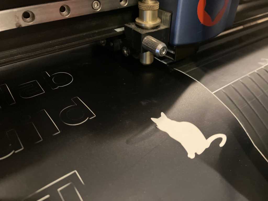
This requires lots of weeding…
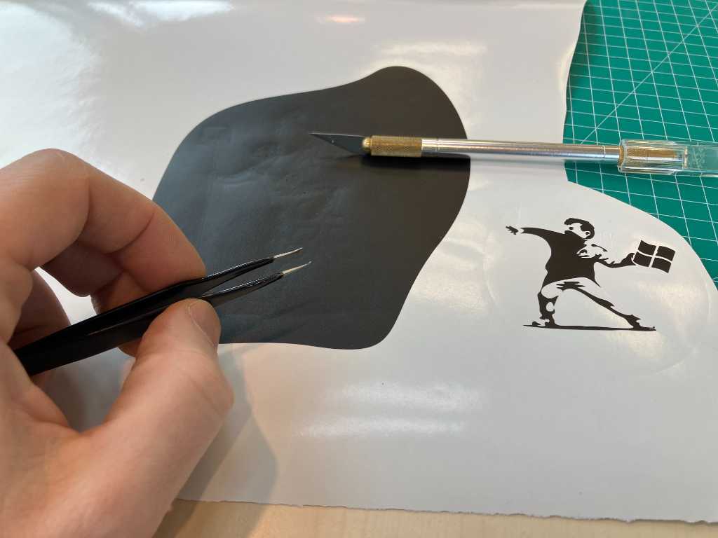
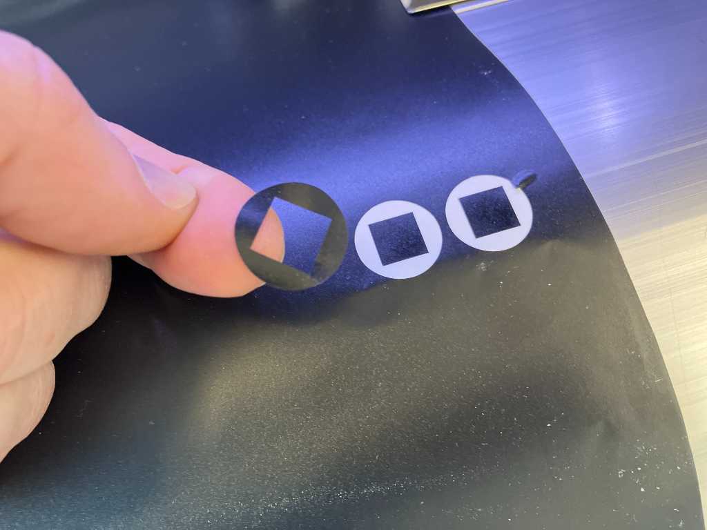
But it’s getting there. Now add some transfer tape to be able to get it onto my laptop:
Ready to be applied!
Nice!
Laser cutting
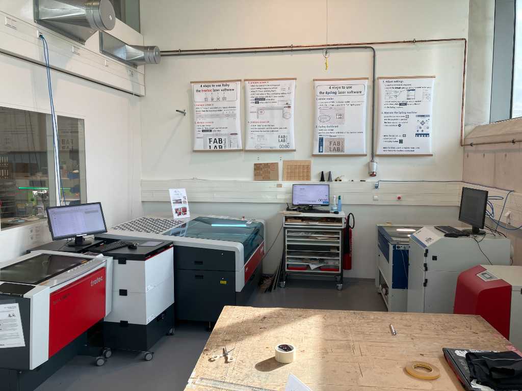
These are the lasercutters that we have in our fablab. A Trotec Speedy 300 flexx (with 60W CO2 and 20W Fiber laser), a Trotec Q500 (80W CO2. not very good at engraving, but great for big cuts) and an Epilog Fusion Pro 36 (80W CO2).
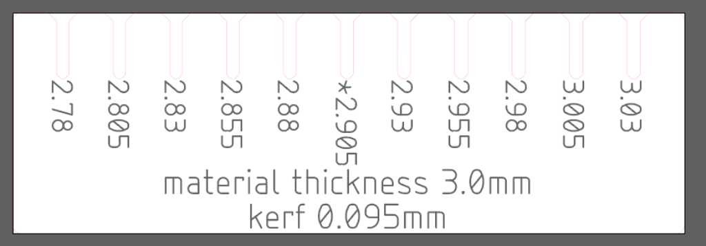
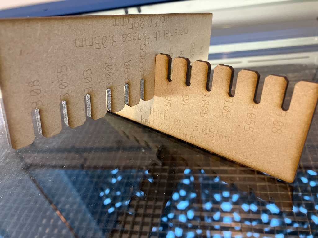
Kerf and offset Epilog
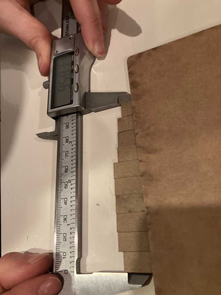
Using Vera’s kerf measurement design I measured the kerf on the Epilog Fusion Pro 30 in our Fablab in Enschede. This is with 3mm MDF.
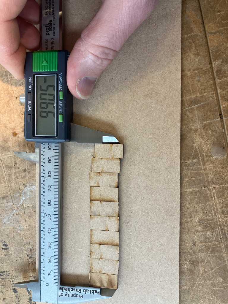
This means a kerf of (100-99.05)/10 = 0.095mm. That’s a great kerf!
So I updated my pressfit testcomb with this kerf and 3mm MDF:
Great fit when using 0.035 offset.
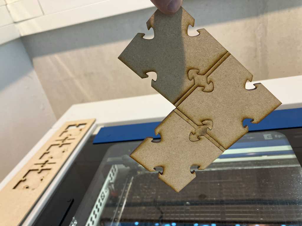
Construction kit design
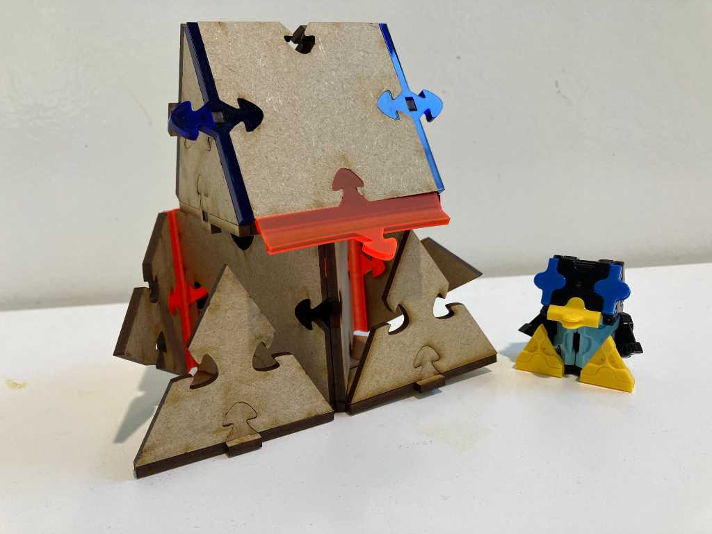
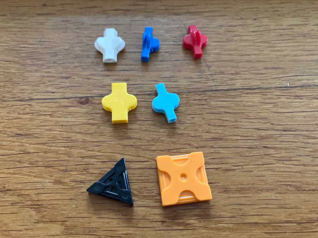
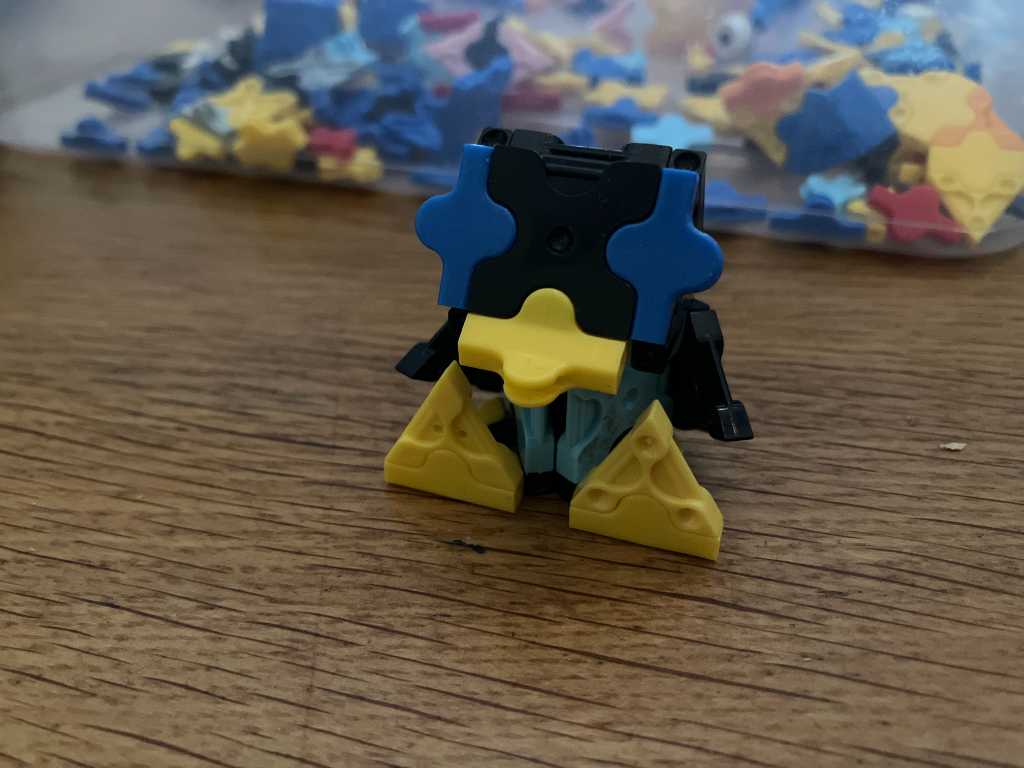
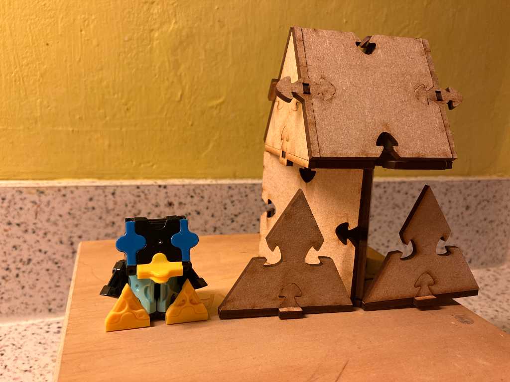
My idea for the pressfit construction kit is based on laQ blocks. My son got a such a kit years ago and he likes it a lot. The idea is that you can create 3D objects using only 7 types of blocks.
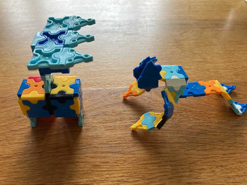
I want to find out if I can make Tux, the Linux Penquin. Hence the name of my construction kit: tuQ. I made it in Laq:

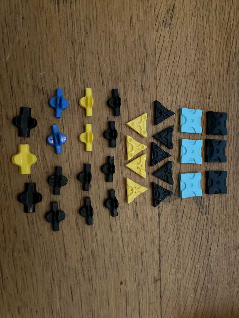
Required blocks for Tux:
- 6 squares
- 9 triangles
- 8 90 degree interconnects
- 4 3-way interconnects
- 3 120 degree interconnects
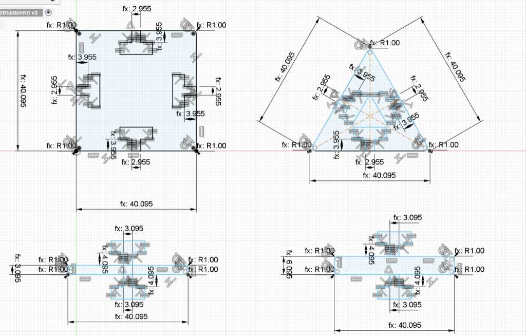
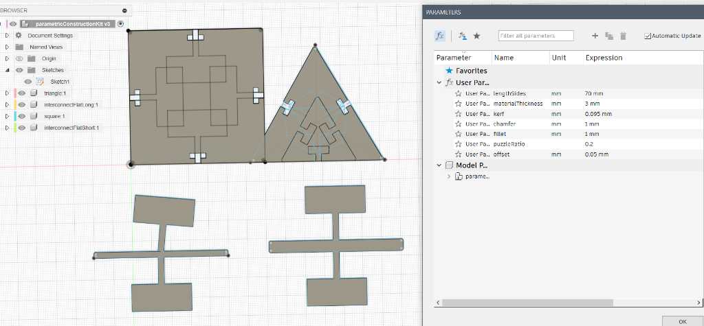
So I started to draw in Fusion.
I thought I had it all figured out, but #fail. When I started to change the parameters, this is what happened:
That certainly does not how it supposed to be.
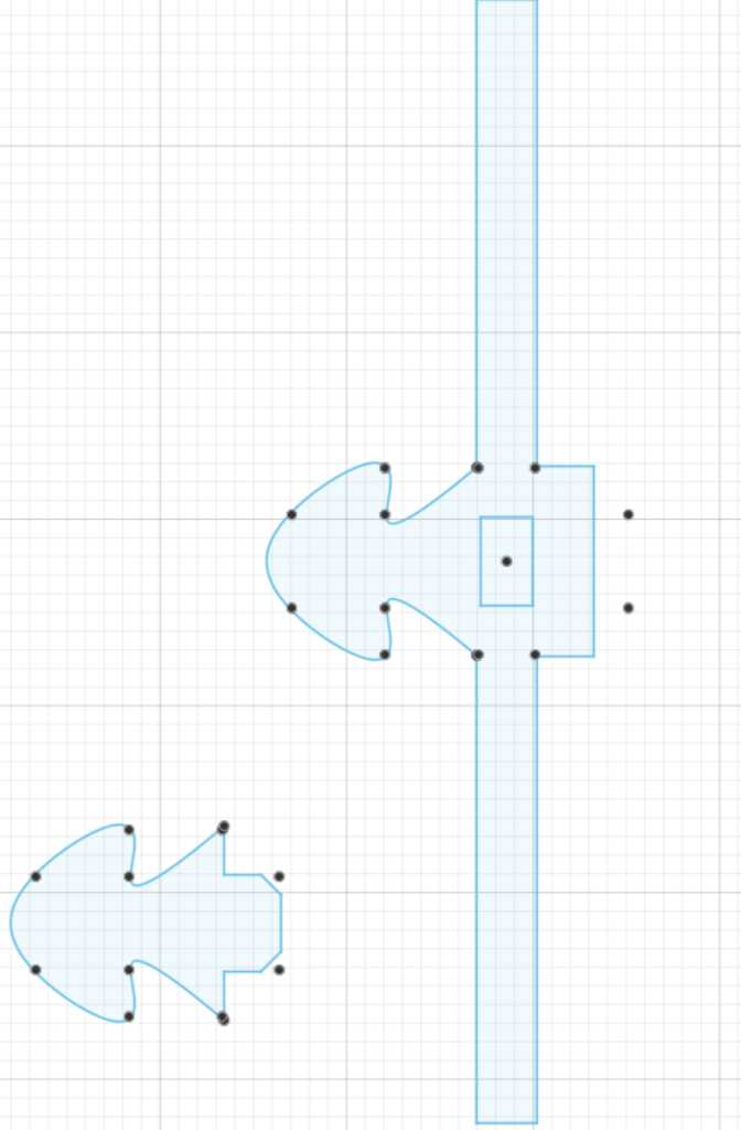
Apparently I did something wrong in setting the constraints. I noticed on more occasions that when I copy certain parts of sketches, not all constraints are copied over. Most probably this is not a bug, but this is my ignorance. It has something to do with me rotating the copy. See image below. The drawing on the left of the origin I did manually, setting all constraints. It is fully constraint, which is indicated by the black lines. The copy on right side of the origin is also fully constraint. I copied the left one and only added the constraint to the origin. So far the expected behavior. The top one is a copy that I rotated 90 degrees and also constraint the same point to origin. As you can see, clearly different:
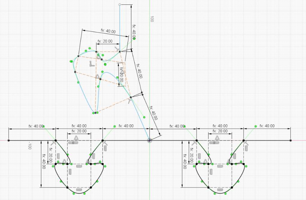
You can see that the constraint symbol of horizontal/vertical constraint is not applied to the rotated copy. I think this is the issue. So I should get rid of this constraint in the original. And instead apply a perpendicular constraint. If I then copy, things should workout.
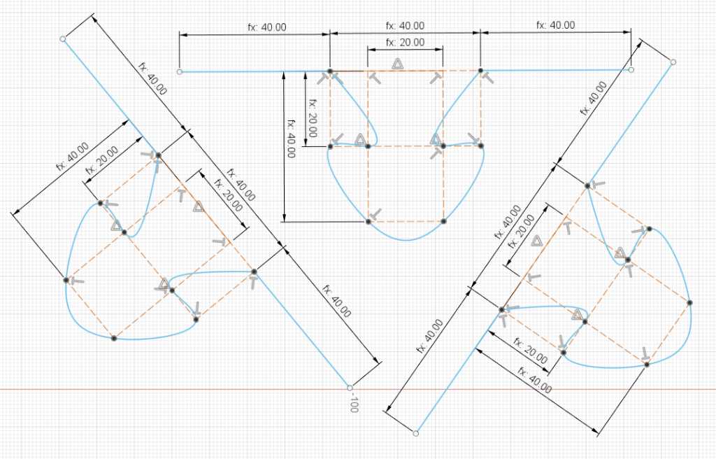
And that worked! Finally this gave me a fully constraint piece:
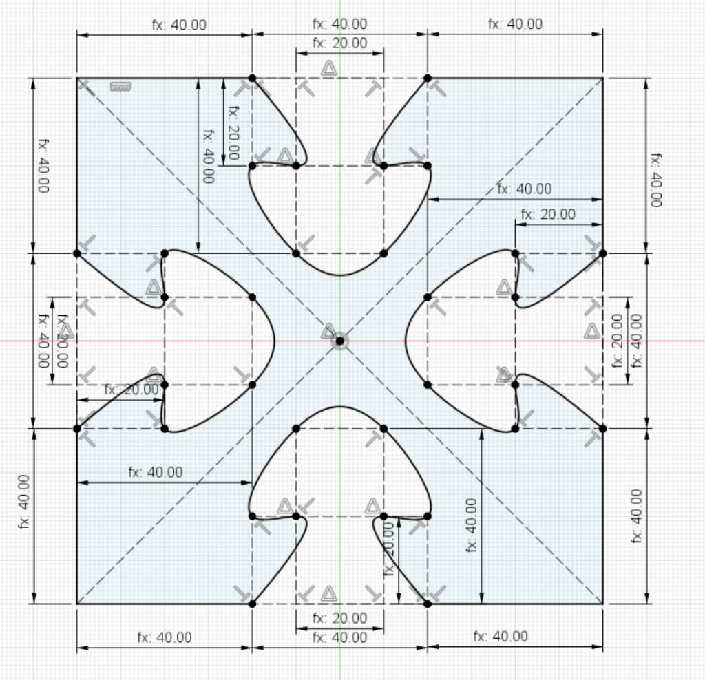
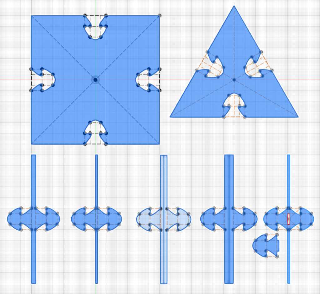
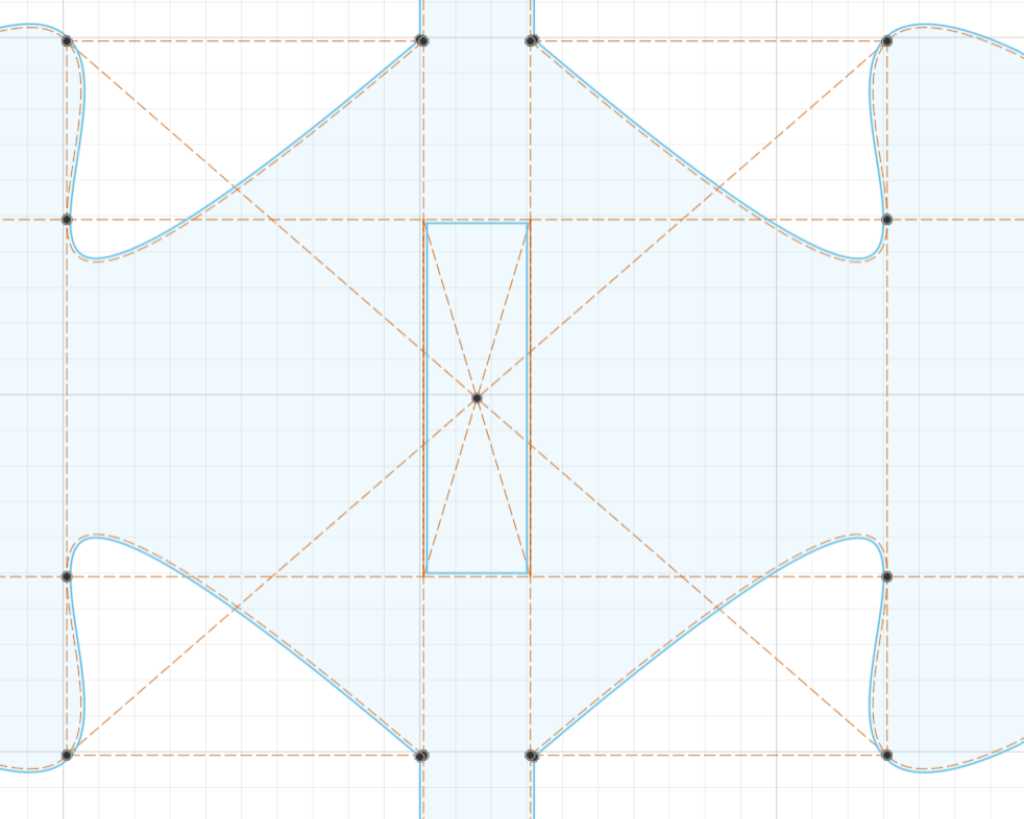
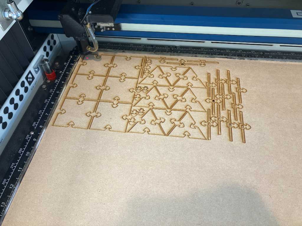
Here are all the designs I made. Ready to cut and play. Also a closeup where the distinction can be seen from an inner cut and an outer cut. Blue lines are cutting lines which are offset. Orange dashed lines are the originals and some construction lines.
Cutting tuQ
Spiral 1
These are cut on our Epilog Fusion Pro 36 (80W CO2) out of 3mm MDF. The cut settings:
- Speed 26%
- Power 100%
- Frequency 10%
So the try-out works. I am able to cut my design. It fits nice and tight. By using the 3-way interconnects, I can even create 3D shapes. That’s spiral 1!
Spiral 2
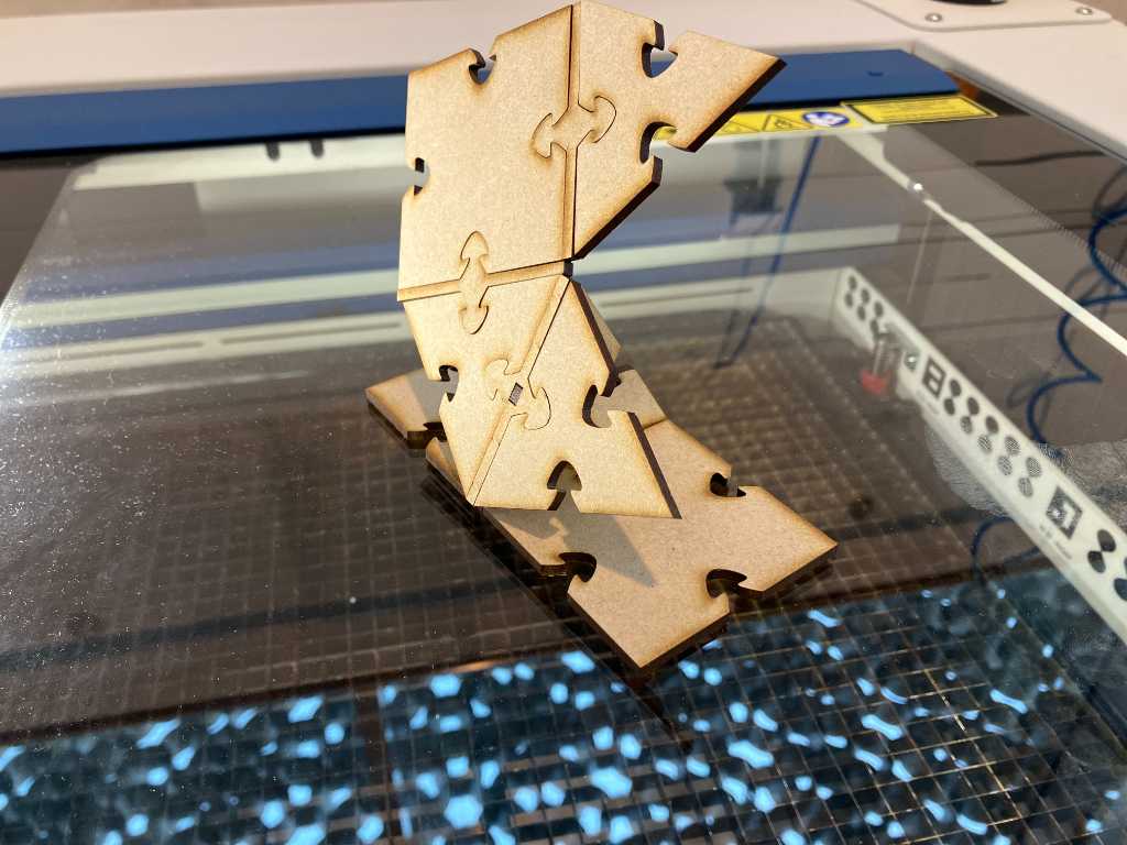
Now let’s go for spiral 2: tuQ
To be able to get a 90 degree interconnect, I designed a small insert:
Spiral 2 done! Here’s tuQ next to little tuQ:
Spiral 3
Now for spiral 3 I only have a few hours. I was very interested in the acrylic bending origami that Neil showed. Basically cut a piece of acrylic, put the laser out of focus and apply laser-‘heat’ so the acrylic bends and gravity pulls it in an angle. I wanted to see if I can do that too.
The idea is to create a 120 degree interconnect for tuQ. The final, working, design looks like this:
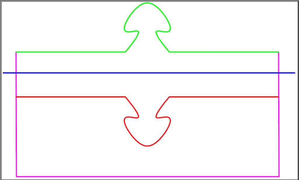
Red line is cut first. Then the purple line is cut. That means a piece of acrylic will fall down, leaving space for the red interconnect to bend down. Next the laser is put out of focus and the blue line is ‘cut’ with low power, essentially heating it up over a larger area. When the red interconnect is bend, the laser goes back into focus and cuts the green line.
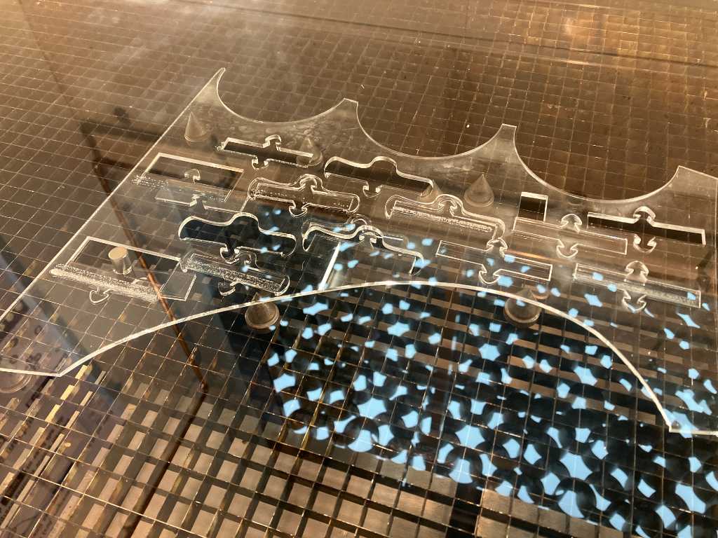
But it doesn’t work at all. With the laser in low power, it doesn’t bend. With the laser higher power, these ugly half-molten lines appear.
I think it doesn’t bend because of the shape of the interconnect. It gets stuck in the leftover material. So I designed a curvature around it. That didn’t help.
The piece doesn’t drop. The head creates bubbles. It’s terrible. Lot’s of tries, redesigns and laser-parameter tweaking.
Instead of a curve, I now have a rectangular shape. That helps, because the parts drops making space for the interconnect to bend. But it doesn’t. I think there are 2 reasons:
- the interconnect has too little weight so gravity doesn’t pull hard enough
- the air assist blows cold air onto the area the laser tries so hard to heat up. Those two don’t go well hand-in-hand. But I don’t want to turn of the air-assist. I’m afraid for bad consequences for the machine/lens.
So I decided to play it rough:
- 40% power
- 20% speed
- 40mm out of focus
- 12 passes
- 2 magnets on either side of the interconnect for additional weight
Adding the magnets means: Cut the purple and red lines (see design above), wait for the laser to go out of focus, pause the lasercutter, wait for smoke to be extracted, open the lid and connect the magnets. After that close the lid and continue.
Although this largely makes a deep cut into the acrylic, it also applies enough heat to make it bend!
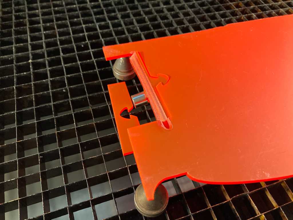
So this finally got me the tuQ I wanted to make:
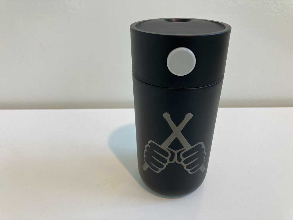
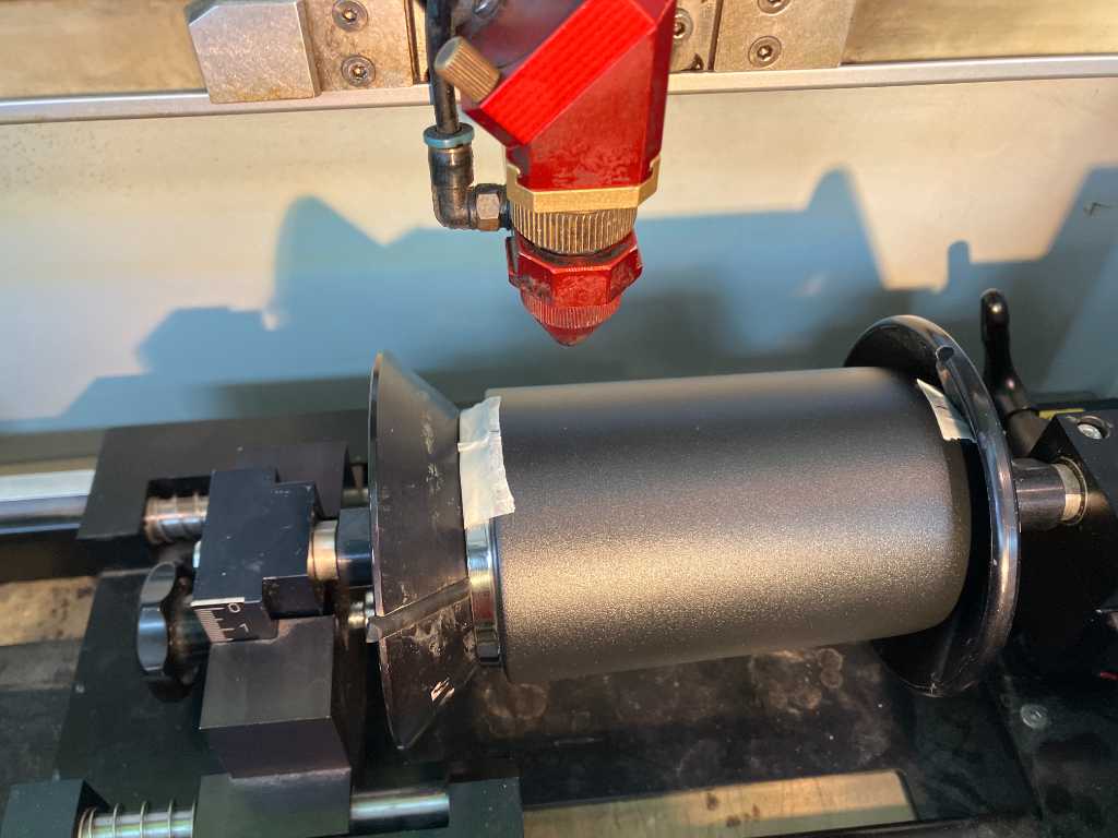
Rotary engraving
A fun thing to do is rotary engraving. We have a rotary attachment for our Trotec Speedy 300 flexx.
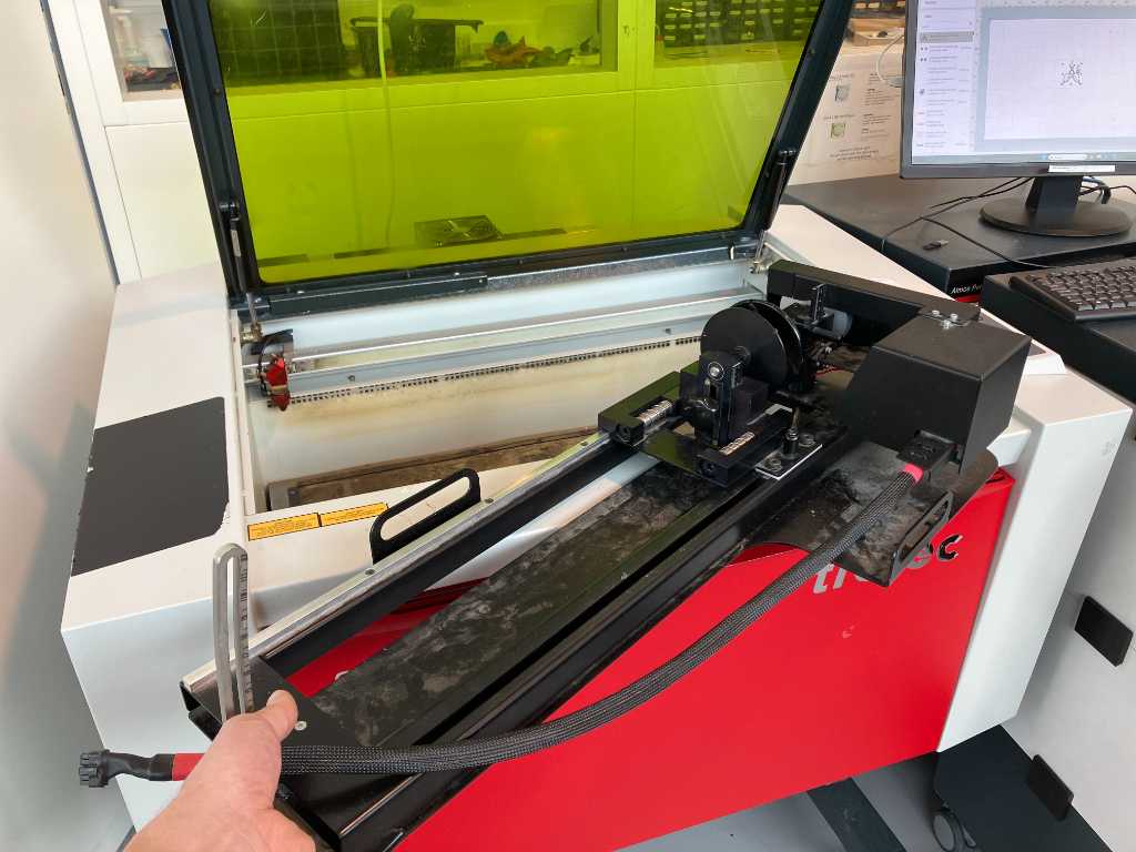
And I have a thermo coffee mug that I use to have a nice coffee in the train to Amsterdam Fablab WAAG. It’s made out of anodized aluminium so a perfect target to engrave.
It’s actually quite easy. Put it into the rotary tool. Use the alignment screws to the the top parallel to the laserhead (the mug is tapered, so need to adjust for that). Next measure the diameter of the mug and apply that value to Trotec Ruby software. I used the following settings:
- speed 20%
- Power 100%
- No dithering
- rotary diameter 72mm
Done: My personal cup of coffee. In my travels to Amsterdam I’m going to like this one the most.
Link to repo
What I learned this week
Successes
I designed a parametric pressfit comb in Fusion in just a few minutes. I was happy about that, because one of my learning goals in Fabacademy is to become more proficient in Fusion. This success was very welcome.
I was able to create an interesting vinylcut design using AI and Illustrator. I’m not good at drawing, but I can edit quite well. So I found out that AI can be my personal drawassistent. The weeding was interesting as well. I never did such a small vinyl cut thing.
For lasercutting, it was interesting to see that when identifying kerf and offset, and parametrically accounting for that makes the actual fabrication of your lasercut design a lot faster. Once defined, always a good fit. Unless your mirrors are dirty.
Fails & Fixes
Lasercutting at WAAG didn’t work out as expected. The troubleshooting we did is something that can occur anywhere with any lasermachine and, although time consuming, I kind of enjoyed it :-)
Fusion contraint solving was frustrating. There are so many constraints that can interfere. And they’re all small little symbols.
Also I was not able to make the acrylic bend the way I wanted. I had to go rough because I ran out of time. Still pretty nice result.
Remember this for next time
Keep a close eye on a lasermachine. Do not take for granted that ‘it just works’. Regularly check if lenses and mirrors are dirty and properly aligned.
Double-check Fusion constraints. Try to change parameters and see if the design actually resizes properly.
Fusion Configurations are pretty neat. It allows you to create sets of parameters that are easily recalled.
Various
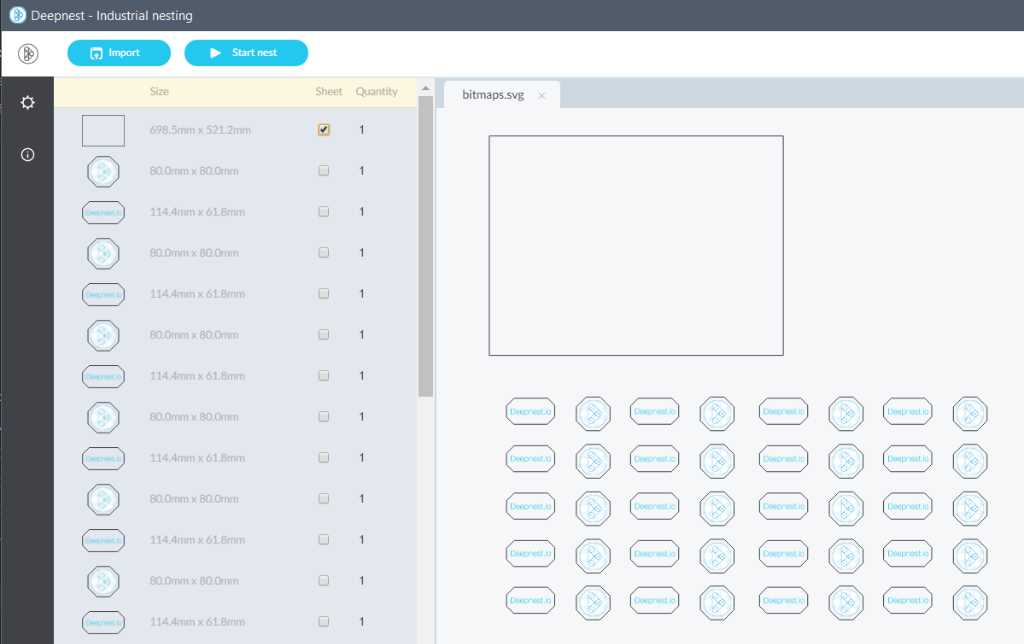
deepnest.io
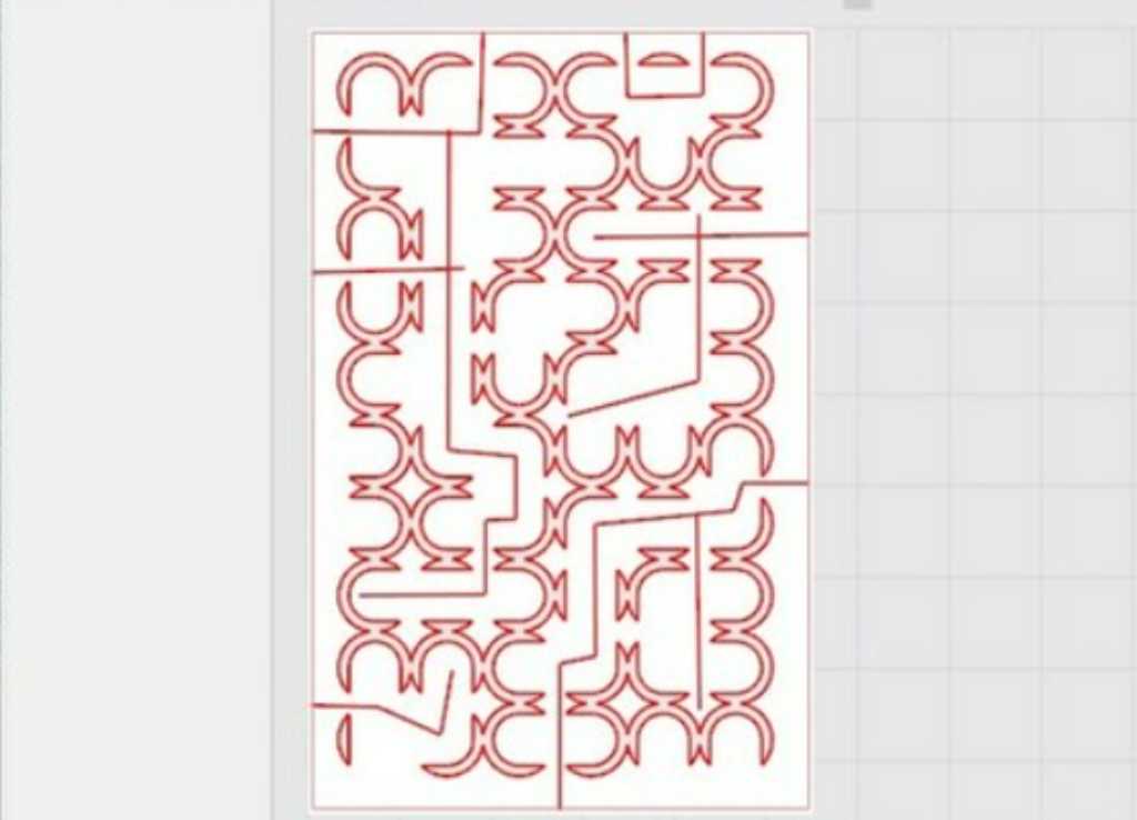
deepnest.io is a very interesting little piece of software. It imports SVG, DXF and CDR files of the parts that you want to cut (including a rectangular shape that represents the sheet that you want to cut it from). Next, you select this sheet and hit Start Nest.
It’s going to place all parts in the most optimal way on the sheet, as to optimize your cutting time and material usage. It’s even trying to opimize for cutting lines, meaning when possible it places objects next to each other so on the cross-section you only need 1 cutting line. Clever. It’s really this easy and should be included in everybody’s workflow.
First thing to do is to go to settings and set the software into metric. Because who needs imperial.
This screenshot is one of the provided samples. I already selected the sheet (checkbox on the left hand side).
Next, click Start Nest and wait…
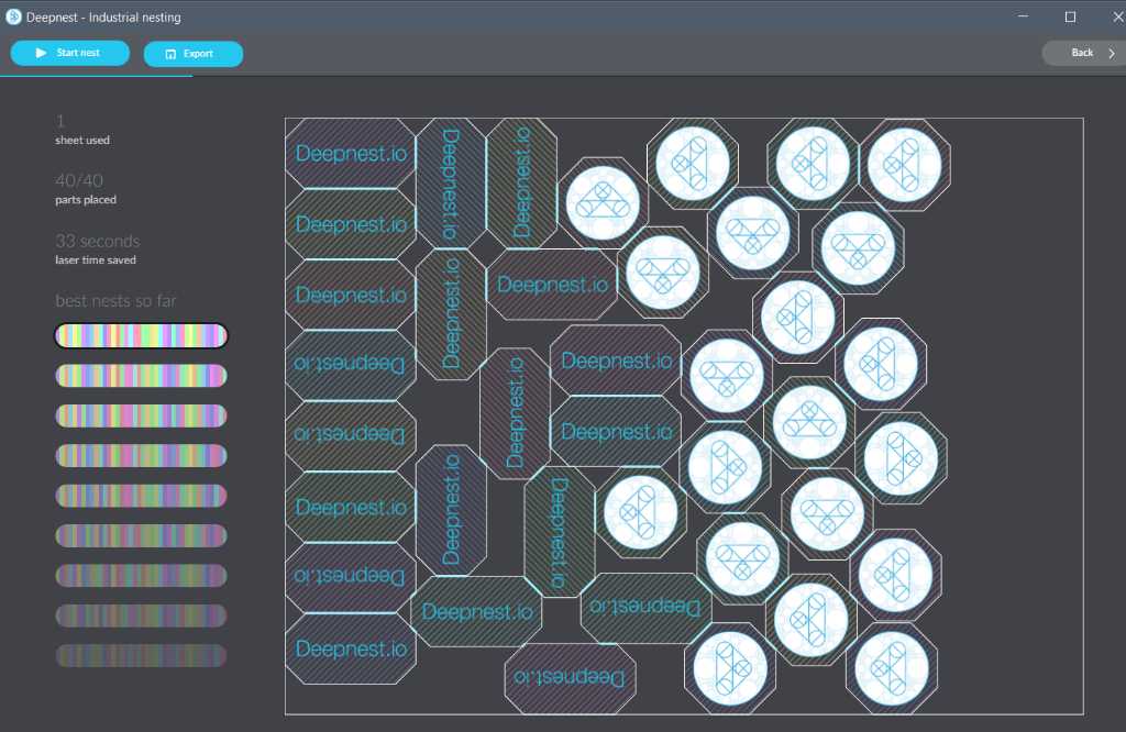
Deepnest will continue finding better ways to fit until you hit the stop button.
On the left hand you can select which one you prefer. Next you can export as SVG or DXF file.
What’s also nice is that you can import multiple files and it will fit all those parts the best way it can.
SVG standard?
Strange thing in the SVG standard:
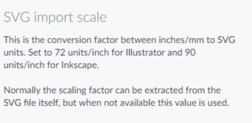
This is a screenshot from the settings page of Deepnet. Apparently different SVG programs treat SVG units differently. I didn’t know that. I thought it was just a unitless format. But there’s a difference if you export SVG out of Illustrator and export it out of Inkscape. In the SVG source file (in the header) there is no header tag that sets this SVG unit-to-DPI.
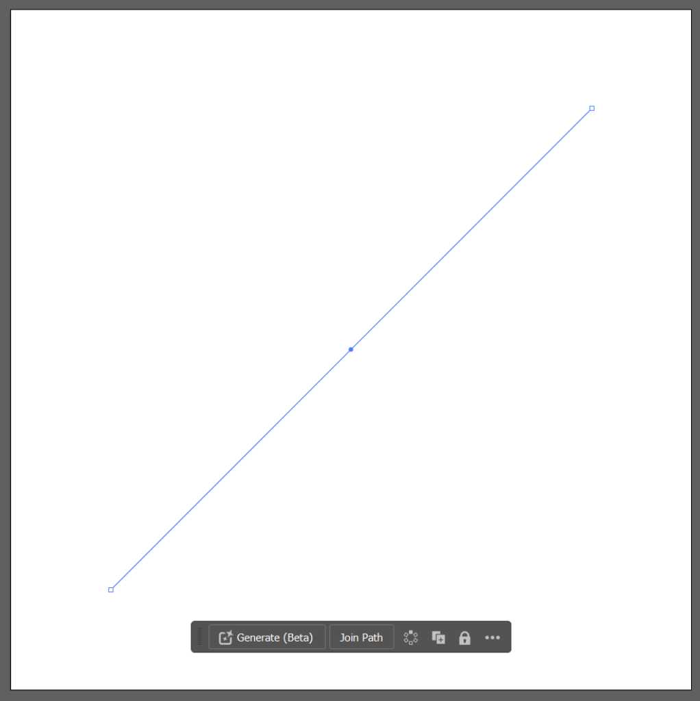
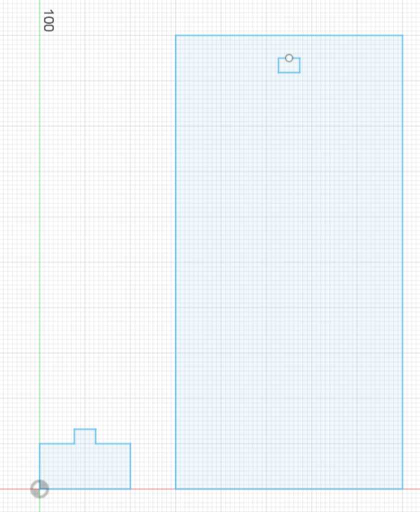
Taking the above image (100x100mm, line of 100mm, linewidth 0.01mm) the Illustrator SVG output is:
<?xml version="1.0" encoding="utf-8"?>
<!-- Generator: Adobe Illustrator 28.2.0, SVG Export Plug-In . SVG Version: 6.00 Build 0)  -->
<svg version="1.1" id="Layer_1" xmlns="http://www.w3.org/2000/svg" xmlns:xlink="http://www.w3.org/1999/xlink" x="0px" y="0px"
     viewBox="0 0 283.5 283.5" style="enable-background:new 0 0 283.5 283.5;" xml:space="preserve">
<style type="text/css">
    .st0{fill:none;stroke:#231F20;stroke-width:2.834646e-02;stroke-miterlimit:10;}
</style>
<line class="st0" x1="41.5" y1="242" x2="242" y2="41.5"/>
</svg>
The SVG of the same image done in Inkscape:
-<?xml version="1.0" encoding="UTF-8" standalone="no"?>
<!-- Created with Inkscape (http://www.inkscape.org/) -->

<svg
   width="100mm"
   height="100mm"
   viewBox="0 0 100 100"
   version="1.1"
   id="svg1"
   inkscape:version="1.3.2 (091e20e, 2023-11-25)"
   sodipodi:docname="100x100.svg"
   xmlns:inkscape="http://www.inkscape.org/namespaces/inkscape"
   xmlns:sodipodi="http://sodipodi.sourceforge.net/DTD/sodipodi-0.dtd"
   xmlns="http://www.w3.org/2000/svg"
   xmlns:svg="http://www.w3.org/2000/svg">
  <sodipodi:namedview
     id="namedview1"
     pagecolor="#ffffff"
     bordercolor="#666666"
     borderopacity="1.0"
     inkscape:showpageshadow="2"
     inkscape:pageopacity="0.0"
     inkscape:pagecheckerboard="0"
     inkscape:deskcolor="#d1d1d1"
     inkscape:document-units="mm"
     inkscape:zoom="0.73382404"
     inkscape:cx="252.78539"
     inkscape:cy="254.14812"
     inkscape:window-width="1328"
     inkscape:window-height="864"
     inkscape:window-x="0"
     inkscape:window-y="38"
     inkscape:window-maximized="0"
     inkscape:current-layer="layer1" />
  <defs
     id="defs1" />
  <g
     inkscape:label="Layer 1"
     inkscape:groupmode="layer"
     id="layer1">
    <path
       style="fill:none;stroke:#000000;stroke-width:0.264583px;stroke-linecap:butt;stroke-linejoin:miter;stroke-opacity:1"
       d="M 12.682641,88.39902 87.317358,11.600979"
       id="path1" />
  </g>
</svg>
Putting these 2 together in one SVG:
<?xml version="1.0" encoding="utf-8"?>

<svg version="1.1" id="Layer_1" xmlns="http://www.w3.org/2000/svg" xmlns:xlink="http://www.w3.org/1999/xlink" x="0px" y="0px"

   viewBox="0 0 283.5 283.5" style="enable-background:new 0 0 283.5 283.5;" xml:space="preserve">

<style type="text/css">

  .st0{fill:none;stroke:#231F20;stroke-width:1;stroke-miterlimit:10;}

</style>

<line class="st0" x1="41.5" y1="242" x2="242" y2="41.5"/>

    <path

       style="fill:none;stroke:#000000;stroke-width:0.264583px;stroke-linecap:butt;stroke-linejoin:miter;stroke-opacity:1"

       d="M 12.682641,88.39902 87.317358,11.600979"

       id="path1" />

</svg>
results in:
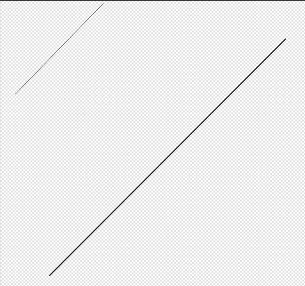
created in editsvgcode.com
A you can see there’s a big differences, although the lines are drawn similarly as a 100mm line.
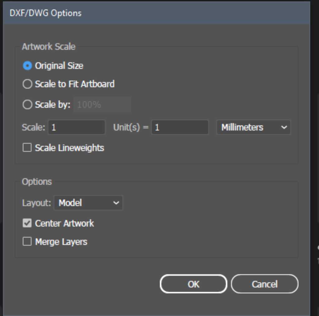
As mentioned on many places on the web (for example here) Illustrator uses 72 DPI (72 dots in one inch, which is the standard for PDF as well) whereas some other programs like Inkscape and kiCAD use 96 DPI. The way to get things to match is is to scale the imported image to 75% (because 72dpi/96dpi = 0.75).
Nadieh posted another Illustrator SVG export issue here: gitlab issue. Gist of it: Uncheck responsive for web checkbox. See images below (taken from fablab WAAG documentation).
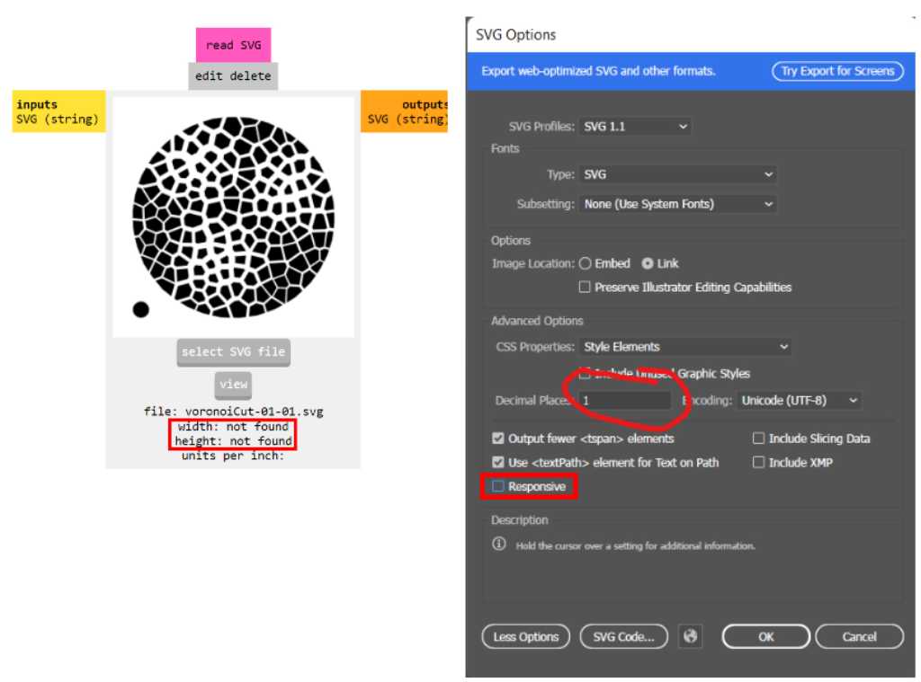
- When exporting SVGs from Illustrator, the SVG file usually doesn’t contain a width
and a height. This causes mods not to read the SVG file. One way to solve this problem
is to open the SVG file in Illustrator and save it again **without a check mark next to _Responsive_**.
What this accomplishes is that the dimensions of the SVG image
becomes absolute and not relative to the dimensions of the medium it is viewed in.
- Another thing to pay attention to is the **decimal places** of the svg. For maximum
quality, this should be set to 7.
Illustrator workflows to remember
Remove overlapping lines
Select the paths that contain overlapping lines.
Object -> Live Paint -> Make
Object -> Live Paint -> Expand
Ungroup
Cut a line
Use the scissors tool. It is under the eraser tool (press&hold eraser icon). Or press keyboard shortcut C.
Scissors can only cut an anchor point. If you want to cut a path mid-line then first add an anchor point using the Add Anchor Point tool (keyboard shortcut = or +).
If you can’t cut there might be another path on top that doesn’t have an anchor point. Lock this path in the layers pane will fix this.