2D & 3D modeling
This page is about everything related to design and modeling mechanical parts. Most of it is related to the assignment 3 of the second week, but along the way new learnings and updates will be added.
2D tools
Basically there’s the distinction between pixel based applications and vector based ones. I’m already familiar to certain extent with a couple of them, like paint and photoshop for the first group and 2D CAD-programs for the second. The ones I will document here are the new ones.
pixel based:
- GIMP
vector based:
- Inkscape
- Cuttle
GIMP
I had a look at GIMP during the second week, but it looked quite inaccessible to me. It look s quite like photoshop and that’s not my favourite application either. In week 4 I did use it for making the changes in my circuit board. After a bit of trial and error it wasn’t that hard, but it has so many features that for a user like me it’s a bit overqualified for the simple jobs I want to do.
For the circuit board mentioned above, I downloaded a simple hippo drawing from internet. After importing it into GIMP I drew a thin line around the the edges with the pencil tool. After that I filled in the outside using the bucket tool. This way I created a file usefull for importing in mods for milling the board outline. You can find the result below:

Later during the course I hade to return back sometimes to GIMP, becaause for some reason (not yet clear) the SVGs coming out of inkscape were not correct when opened in mods for milling my boards. Converting the to PNGs in GIMP sometimes helped (mods also has a tool for importing PNGs).
Inkscape
I used Inkscape to make my vinyl cutting designs. It also took me a while to get used to. What is confusing sometimes are basic GUI priciples that are different for every application you run into. With basic principles I mean the way you start and stop commands and the way selection tools work. In the end it’s just a matter of perseverence, rely on duck duck and trial and error.
Nice thing of Inkscape is of course that it’s free and open source. I used it quite a few times during fabacademy, but the SVGs it produces are sometimes unexpectedly faulty. I had a lot of trouble with them when importing in mods for our board milling machine and turned in the end often to PNGs instead. So if anyone has a tip for a better vector based 2D tool, let me know.
I used Inkscape for the sticker design for the 2D cutting week. It’s just a simple three character text, so easy to create. But I did encounter some issues there. More about that in a chapter fo the cutting page:
Cuttle
For the computer controlled cutting week I explored a new tool: Cuttle. In the tutorials it seemed quite easy, but what this doesn’t show, is the details, that contain many devils. It took me quite some time to get what was going wrong and on top of that, some of the UI is quite misleading.
To start wit the first one, if you want a polygon, the menu says “polygon from edge” and shows in the icon two point at the end of one of the edges. If you do that, for a triangle you end up with a smaller edge than wanted. My edge was defined 140 and it turned out 121-something.
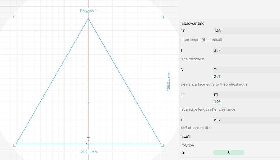
After a while I discovered that the dimension you give for a polygon is the diameter of the circumscribed circle.
3D modeling
Fusion360
First start in 3D modeling was an instruction by Michelle about Fusion360. This is one of the main products of Autodesk. Because I have some experience with old versions of Autocad it looked familiar. Biggest change since then is that they now also enable parametric design. With a bit of learning on the go, it won’t be too hard to use that. Here is my firat design try-out.
Further down below you can find more about design in fusion in the chapter of the foldable trolley.
Rhino
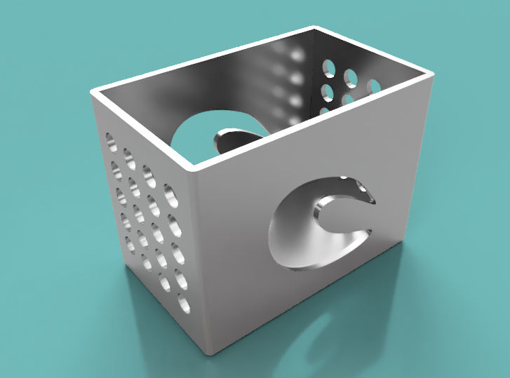
Because it works without cloud, I wanted to give Rhino a try. It has a friendly 90 days evaluation licence available. So I downloaded it from rhino3D.com, watched a bit of tutorials and gave it a try. My main interest is in designing in solids. I want to create constructions, parts and assemblies. Turns out Rhino is primarily a surface modeler. It does use NURBS, which is good, a drilled hole should not be faceted, but when creating solids, it creates their surfaces. My example below shows the problem. I created a box with some holes and was able to delete a surface and the box turned out to be empty.
FreeCAD
We had an instruction about FreeCAD to get us started. Nice feature about FreeCAD is that it works with a spreadsheet to manage your parametrics. But I had at the start problems to understand its user interface. It didn’t come to me intuitively. After a bit of effort I was able to do some design, but ~I still didn’t like it. The way it works generates a cornucopia of constraints and even in a small design it’s already generating a load of conflicting ones. For me this doesn’t work, so for now I’m not going to do more effort.
OpenSCAD
Our fellow student Bas gave us a very good instruction for OpenSCAD. This tool is much more my liking. Despite not being a programmer I was quickly able to follow its design principles and it has many advantages. Unfortunately it has one big disadvantage for me, it uses polygons, so the quality of the surfaces depend on the number of facets you define. If your into mechanical engineering, you don’t want your bearing hole to be faceted.
Blender
Last tool I want to discuss is Blender. I had downloaded it already some years ago and it didn’t come to me naturally. So at that point I decided that it had a learning curve that’s too steep and let it go. But Ferdi gave us a very good interactive instruction and I do think it’s a nice tool. But it’s not really made for engineering purposes, but for visualisations it’s super I think.
Comparison
I’ve made a list of aspects that are inportant to me for the choice of tool.
| aspect | Fusion360 | Rhino | FreeCAD | OpenSCAD | Blender |
|---|---|---|---|---|---|
| kernel | NURBS | NURBS | NURBS | Polygons | Polygons |
| solids or surfaces | solids | surfaces | solids | ? | surfaces |
| UX (for me) | ++ | ++ | – | ++ | +/- |
| needs cloud | yes | no | no | no | no |
| open source | no | no | yes | yes | yes |
| pricing | monthly | buy | free | free | free |
Conclusion for now is that I stick to Fusion360 for my mechanical design and if I have time I will try to make a rendering and animation in Blender.
Trolley
At this moment I haven’t decided on a final project yet. Therefore I turned to the old product idea for a foldable trolley I had to boost my 3D modeling skills. When I investigated this idea, I didn’t use 3D models to figure out how the foldable parts should work (see the sketch on the foldable trolley page). Now I can use the 3D modeling assignment to simulate the mechanism.
Modeling
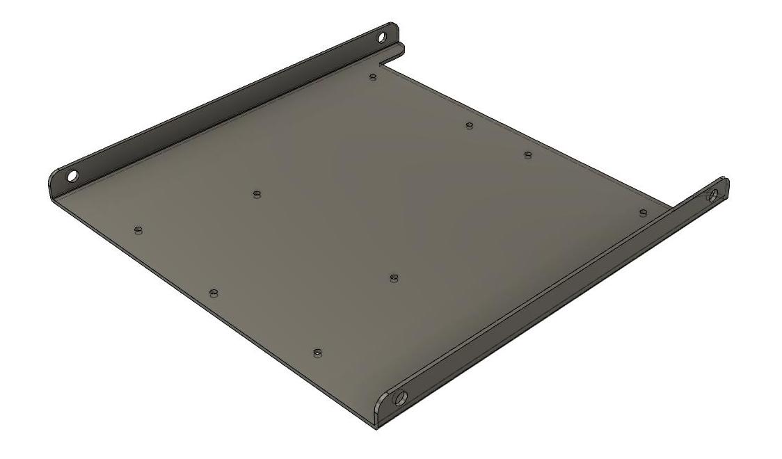
For modeling I turned to Fusion360. At first sight it looked familiar to me, but the devil is in the details as always. Making a 3D model isn’t that hard. I hardly needed any tutorial for that. A simple model like this one for the base plate is easy to make.
Here’s a short video of the design of the wheel. Basically I swiped a sketch over 360° and cut out the holes with other skeches.
BTW: for anyone interested, the tutorials of fusion are fairly good. Their site is pretty crappy, so you will only find it from the help function in fusion, but here’s a link.
The difficulty came when making multiple parts and assembies. The easy way I started with was to just create separate bodies. But that doesn’t work properly, because Fusion automatically merges different bodies into one if they have touching faces. That’s not always what you want.
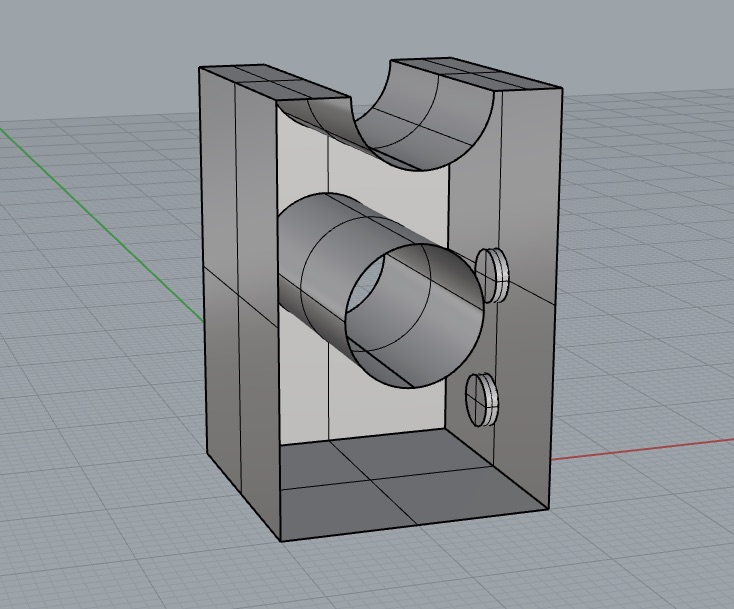
But you can also create new components. In that way they won’t be merged and you can draw these with new bodies at the right location, like the bearings on the base plate in my case. Or like the example below, that is representing the handle of the the trolley and is made up out of four parts.
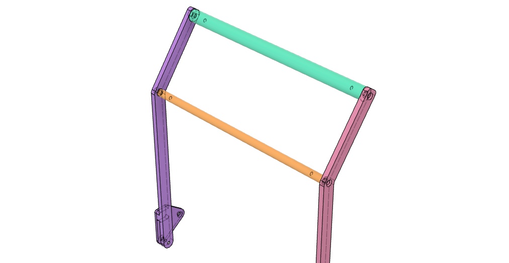
But this creates weird behaviour when making an assembly model. In assembly you can join parts together and give them degrees of freedom constraints. If I import the 4-parts model of the handle and apply that to one joint of the handle, only that part is aligned and tha others are not even when they had constraints in the original 4-parts assembly where they came from.
To solve that I have looked into more detaails of the joint commands. By using the “joint as built” you can assign a joint status to components that are already in place. Default it is set to “rigid”, but you can assign any other type with degreas of freedom too. So I’ve first made rigid joints in the subassembly of the handle and then updated the model.
The final model archive can be found here: trolley assy v5
Rendering
The rendering I did for this first modeling was only within Fusion360. I have assigned some materials, mostly alunimium and rubber for the handle and made the following picture with the coloured model as an insert.
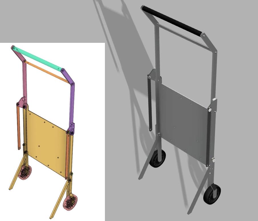
Animation
In the render picture you can see that the link beams are not yet connected to the wheel swing arms. The link beams are not exact the right length and when using the “joint” command it didn’t connect them and moved the swing arm in place. It returned an error for conflicting constraints.
I wasn’t able to figure out how to solve that, so I made a work around. It’s easy to sketch a component in place, so I created a plane at the location of the left link and redesigned the link with the exact length from joint to joint. Now I was able to apply the “joint” command without error. The result is this animation.