3D Scanning & Printing
Subject for week 5 is scanning and printing of 3D objects. Part og that is a group assgnment to characterise our 3D printers.
Group assignment
We have split up into 3 groups to investigate all 3 filament printers we have: - Ultimaker 2 - Prusa i3 Mk3 - Creality Ender-3
Ultimaker 2
Our group took a look at the Ultimaker and made a testprint. Most items of setting up the printer are easy and can be done almost without prior information. Some small remarks: - the filament feeder has a strong spring loaded transport mechanism and you have to push the little knob up to release it. - the filament has a bigger diameter than for the other machnes: 2,85 mm - it’s not a direct drive, so the transport line from motor to nozzle is quite long
We also had some mishaps at the start:
- the first Z-leveling was wrong so there was only a thin layer to almost none printed (more about that below)
- we had an error saying “printing outside area”, because we forgot to chose the right printer in prusaslicer to turn the SLT model into G-code
Most difficult part is leveling the Z-axis. The software will guide you through the process, so that not the issue, but they use a very close tolerance. To deal with that one needs to pay attention to the next issues:
- it levels on 3 points and before calibration all adjusting screws should be in a central position allowing adjustment in both directions
- the adjusting screws are spring loaded and it’s difficult to feel the exact clearance between plate and nozzle
- the force of the spring is varying much with the amount it’s turned in or out
- the last calibration round is done with a sheet of paper and if this is too thin, the nozzle will start too close to the plate
But finally we got it right:
Prusa i3 Mk3
The Prusa seems to be the most reliable and accurate machine at De Waag. Our fellow student were the first ones to finish the test print.
Creality Ender-3
The group that tried to run the Ender in the end had to give up. They did a lot of work on Z-leveling, which is even a lot harder than on the Ultimaker. When the finally had that right the model didn’t stick to the print bed and there seems something wrong with that.
Comparison
Eventually we had two prints to compare. The pink one is from the Ultimaker and the red one from the Prusa.
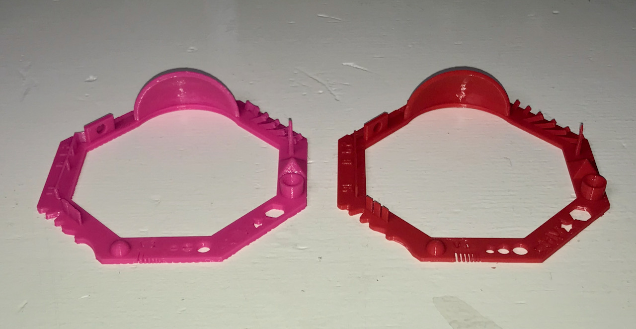
There’s a noticable difference between the two. The Prusa result is a lot better: - more detail - sharper contours - better overhangs
The causes we assume from the Ultimaker side is that we suspected at the start that the nozzle temperature was to low and raised it a bit (from 205 to 210 °C) as we dit with the bed temperature (from 50 to 60 °C).
3D Scanning
iSense
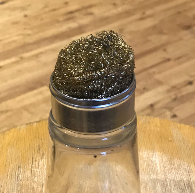
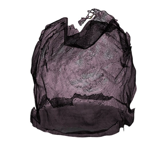
Scanning is part of the assignment, but the scanner here is totally outdated. It’s the iSense from 3Dsystems handheld scanner with accompanying special software. Performance is bad and you reach quickly the boundery of what’s possible. Notes on my trials: - shiny ogjects are hard to scan, it needs surface texture to scan properly - black objects are impossible to scan - rotating the object with scanner on a fixture doesn’t work (apparently it uses also background image as a rweference) - parts that are out of the center like a long flower will not be found
| objecct I scanned | result |
|---|---|
 |
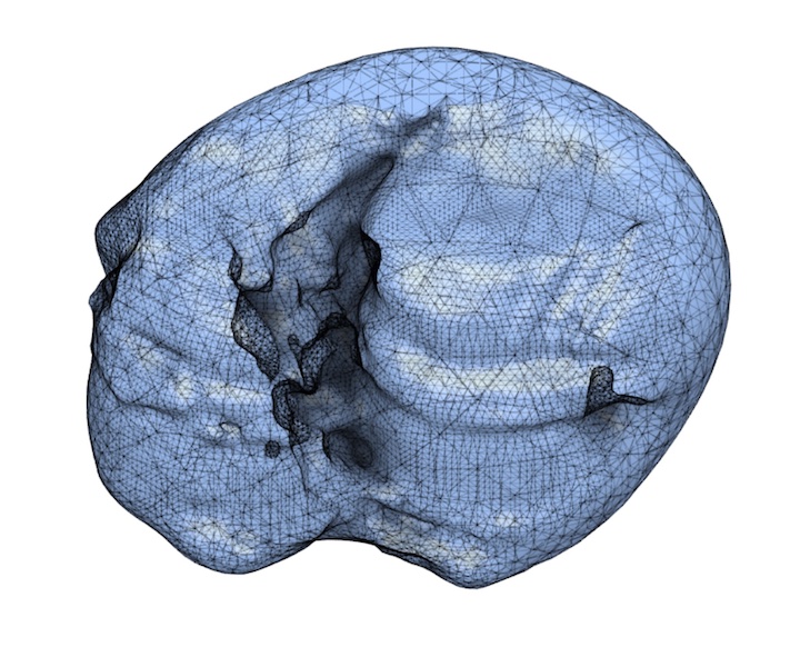 |
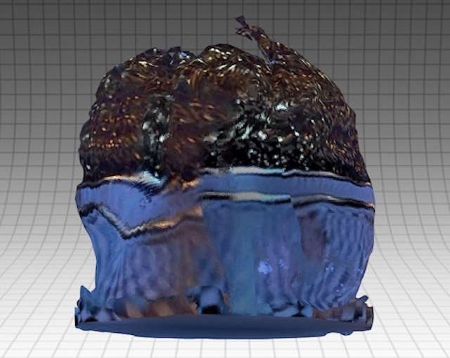
Qlone app
As an alternative I tried the phone app Qlone from EyeCue Vision. Her again I tried to use a setup holding the camera and rotating the object. Here it worked, because the reference for the app is the printed reference sheet on which you place the object. This reference sheet can be downloaded frmo this page or from within the app. You just place the object in the middle of the sheet and the app will show you the proceeding results of the scanner.
It has better results and looks good on your phone, but the model is still not very accurate. To make it realistic the texture is in the app automatically maped on the mesh, but when exporting the information is not integrated in the OBJ file.
| model in the app | model from OBJ in Fusion |
|---|---|
 |
 |
3D Printing
For my 3D printing assignment I have designed a locking mechanism for my foldable trolley project. The design of the trolley was already in Fusion360, so I have added there the locking mechanism. For details see the chapter on the trolley page.
Generating G-code
To generate the G-code I used prusaslicer. It has predefined settings for the Prusa i3 MK3, which is by far my favourite tool for 3D printing. The interface is easy to understand and I didn’t need to adjust much. On the settings page I have listed the parameters I used.
Slider Test
The sliding mechanism should have as less tolerance as possible. To try out what is achievable, I made a small test object. I started with a gap of 0,2 mm on all sides of the sliding rail. It’s a mechanism you can’t produce with subtractive production as you can see in this section analysis.
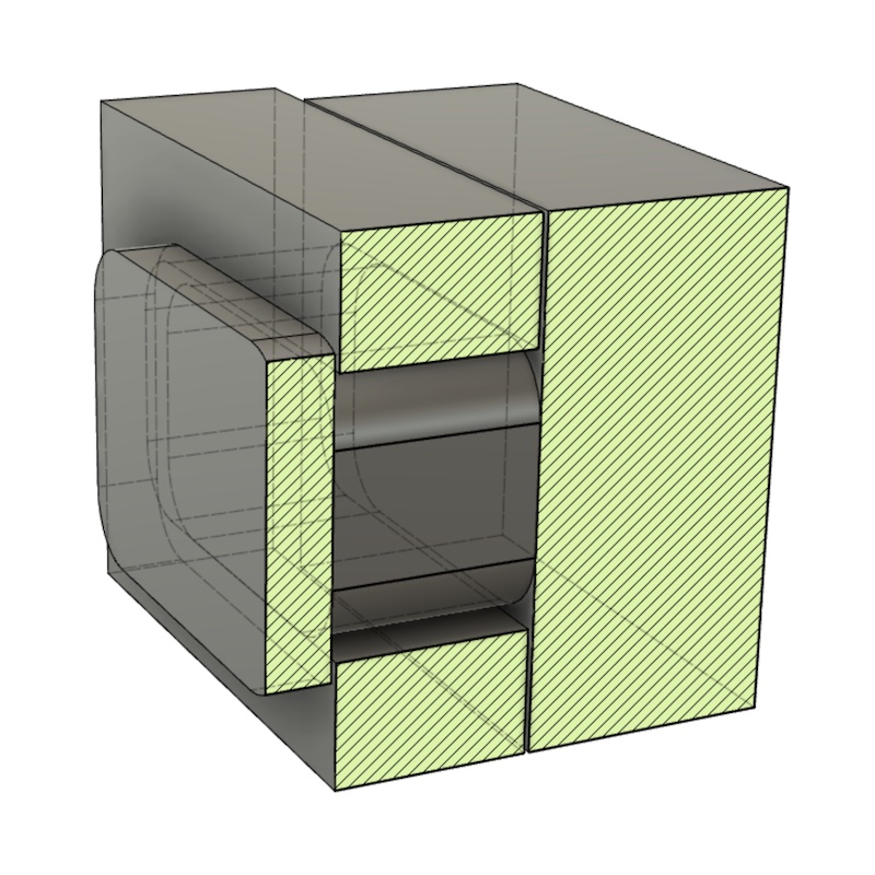
Because it should be a bit flexible, Henk suggested to use PET. If you look at the materials table this is a workable choice, though PA (nylon) might be better on wear resistance. Disadvantage of PA is that it will absorbe more water.
Anyway, the first test failed as you can see in the pictures. When trying to loosen the slider, it broke into 3 pieces. What it also indicated to me is that PETG is more brittle than expected.
| pic 1 | pic 2 | pic 3 |
|---|---|---|
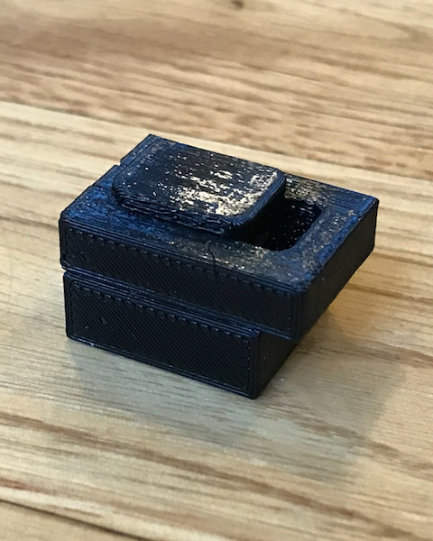 |
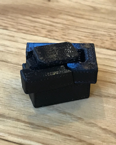 |
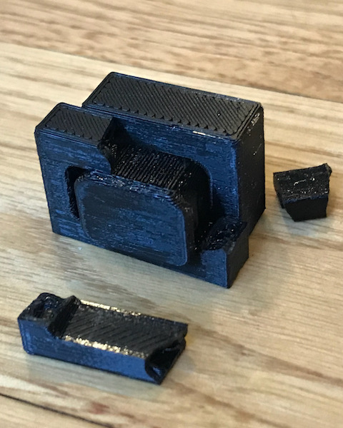 |
Solution to this was to djust the gap, so I increased it to 0,25 mm. It’s not much, only 25 % more, but it worked. I carefully released the slider by pushing it with a limited amount of force in a vice. The result is shown in the small video.
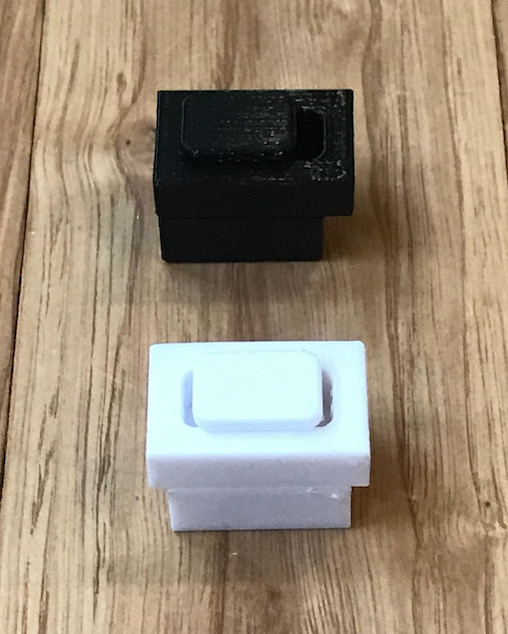
But at some point Henk suggested another material: Iglidur PF i150. This is material specifically for low speed repetitive movements and has less friction and less wear. In the defaults of the Prusaslicer there’s no preset for this material. I’ve used the PETG-settings as a basis and adjusted the parameters according to the specs found on the material specification of Iglidur. The specifications are a bit generic, but it worked ok for the print to adjust mainly the following:
- Change bed temperature to 50 °C at first layer and 55 °C for the other layers
- Change nozzle temperature to 240 °C at the first layer and 250 °C for the others.
The result is in the picture with the white version being PF and the black verion being the PETG. It was very easy to loosen the slider and the surface is much more smooth.
The latest versions of the this test are here:
For the rest of the story Please go to the trolley page chapter about the locking mechanism