Foldable Trolley
The foldable trolley is basically an add-on that allows you to unfold wheels and a handle bar. The design was reversed engineered during the 3D modeling assignment, so have a look at the simulation there to see how it works.
When I made the first prototype I drew a few sketches to check the folding principle and to get an idea of the dimensions.
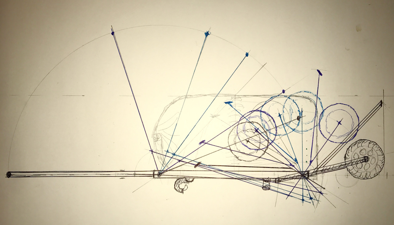
Based on this first prototype I did some reversed engineering (see the link above) to have a start for further development. This is how this prototype looks:
| folded with pannier | unfolded without pannier |
|---|---|
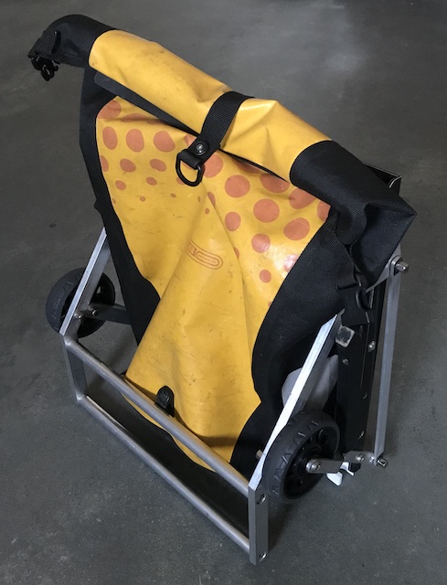 |
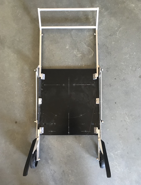 |
Locking Mechanism
The prototype works, but not good enough yet. It makes a rattling noise when you wheel it over the pavement. The main cause is the locking mechanism that has a lot of play. Combined with the use of aluminium frame parts that makes it very noisy.
The 3D printing assignment gave an excellent opportunity to improve this. I have designed a sliding lock that secures the wheel arm. Because the pivot of the handle bar link is perpendicular to the the hinge of it there’s no need to secure the handle bar separately.
Designing and printing this component was part of the assignment. In the slide test chapter you can find my documentation with the first results of a test version of the sliding mechanism.
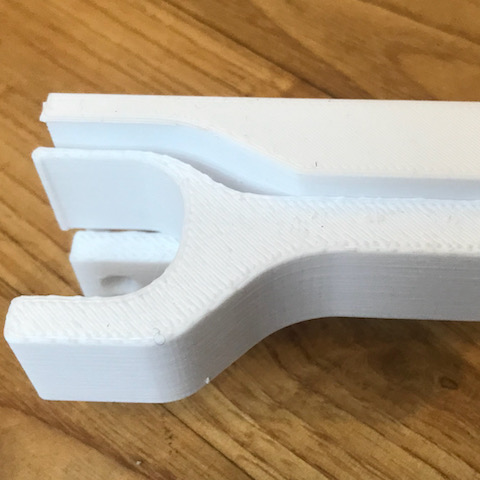
Sliding Lock
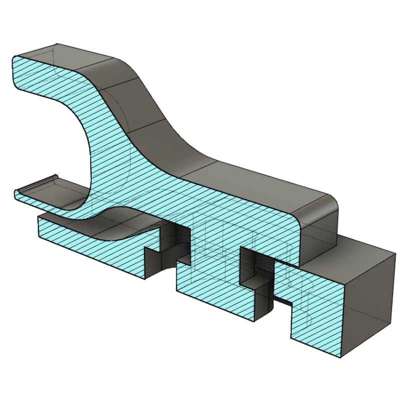
After the test version and all seemed to be working, I started on the component I wanted to make, the locking mechanism for the foldable trolley. How it should work is shown in the video taken from Fusion360.
This also is designed for 3D printing without any sub-components as you can see in the section analysis.
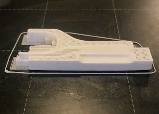
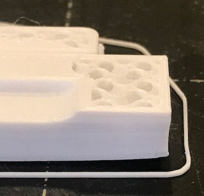
Unfortunately again some mishap. This part was bigger than the test slider, so after some time it showed warp on one edge as you can see below. Our deputy-instructor Michelle pointed out that I should have look at the troubleshouting page from simplify3D that has some useful tips & tricks. From there I added a brim of 10 mm and raised the bed temperature a bit to the max of 60 °C.
| whole print | warped end | final result |
|---|---|---|
 |
 |
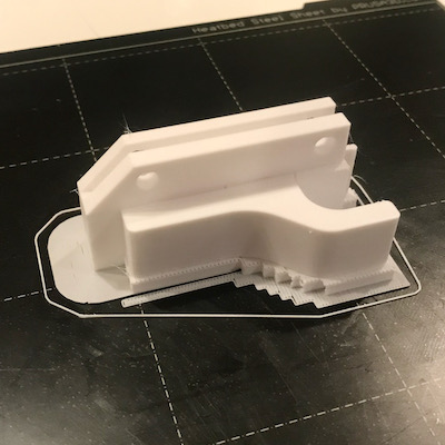 |
The final result is working like intended:
But some improvement is still necessary:
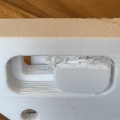
- The gap for the sliding part was 0,25 mm, but for the locking block it was 0,5 mm. This turned out too big to print without support. On the bottom part it had no surface to print and after doing some messy part, it started to get into it’s intended form. Improvement: reduce the gap to the some as the slider and use support for the open overhangs. Maybe a sightly lower nozzle temperature could assist too.
- There is a lot more play in the slider than with PETG. Because it loosened so easy, testing with narrower gaps should be tested to check what de limit is of the possible tolerances with this way of printing locked in parts.
- The support side is still quite rough. This side is most visual in the product, so it’s probably better to print it on the other side.
| overhang problems | rough support side |
|---|---|
 |
 |
I have to produce a mirrored version of this component too and will try out the ideas above when doing so. The result will added later here.
The CAD files used for this (latest versions):