Balance Bike
The balance bike has turned into a complete project now. I have been changing some parts on the way and I also came up with the idea to get the wheels rubber tyres during the wild card week. The end of this project should be a guideline for anyone who is interested to make one for her or his own (grand)children.
- For the basics of the machining please go to the balance bike machining page
- For the first test of the tyre go to the moulding & casting page
Design
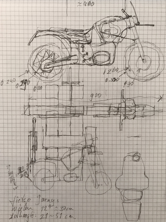
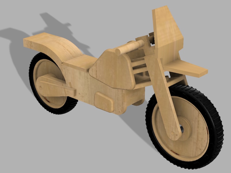
I started with a bit of sketching, or maybe doodling is a better word. For CAD I used Fusion360, just because it’s my fastest route to design something. And because my timeslot for the shopbot was already on Saturday I had only one day to complete my design. It was a long day, but here’s what it looked like after rendering.
| sketch | render |
|---|---|
 |
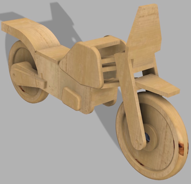 |
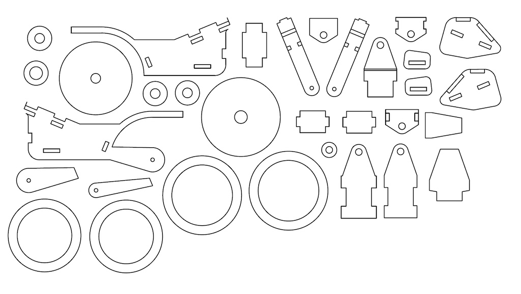
This version wasn’t complete yet, but all parts that have to be milled are there. I will make some parts like the wheel axles and the handlebar with manual techniques.
What I miscalculated is the time you need to generate drawings. There’s probably a faster way, but I had to create a view for each part and hide all others manually. It’s not difficult, but a lot of work and you have to do it in a structured way for not forgetting any component. BTW: I left out a few, but they are just rectangles and it’s faster to cut them with my table saw.
The latest version of the design files are downloadable here:
First Results
The assembly is also quite time consuming. Because of the inaccuracy of the fit holes, I have to do a lot of post-processing using sandpaper and files. Sometimes I also forgot to include some features. Like for the wheel, I should have included drill holes for the dowels to connect the rims. Now I had to do that by hand. BTW: I used the fillet milling bit in my workshop to change the appearance of some parts.
Design Changes
There are some parts I changed along the way when assembling the bike:
- I made the front mud guard a bit longer, just for aestheticaal reasons;
- The wind screen recieved an angle of 15°, also from aesthetical considerations;
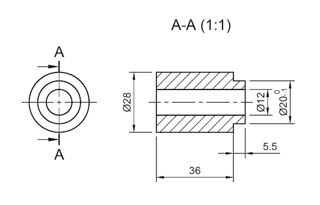
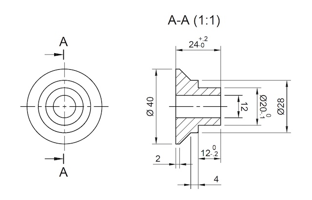
- I designed bushings for the front and rear wheel and ordered them from a lathing company (see drawings);
- The handle bar construction seemed a bit to weak to me, so I added two screws going from bar down to the top plate;
- Not in the model yet, but I added a construction to be able to change the height of the saddle;
- And BTW: at a furniture refurbishment shop they added foam and leather for the seating.
| front wheel bushing (2x) | rear wheel bushing (1-sided) |
|---|---|
 |
 |
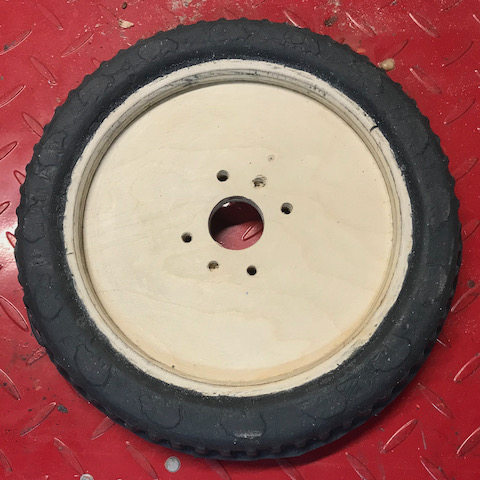
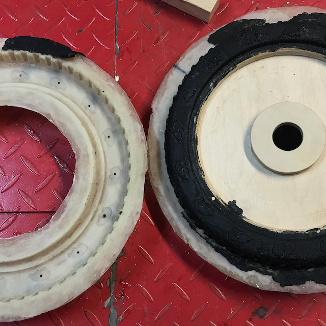
Casting the Rear Tyre
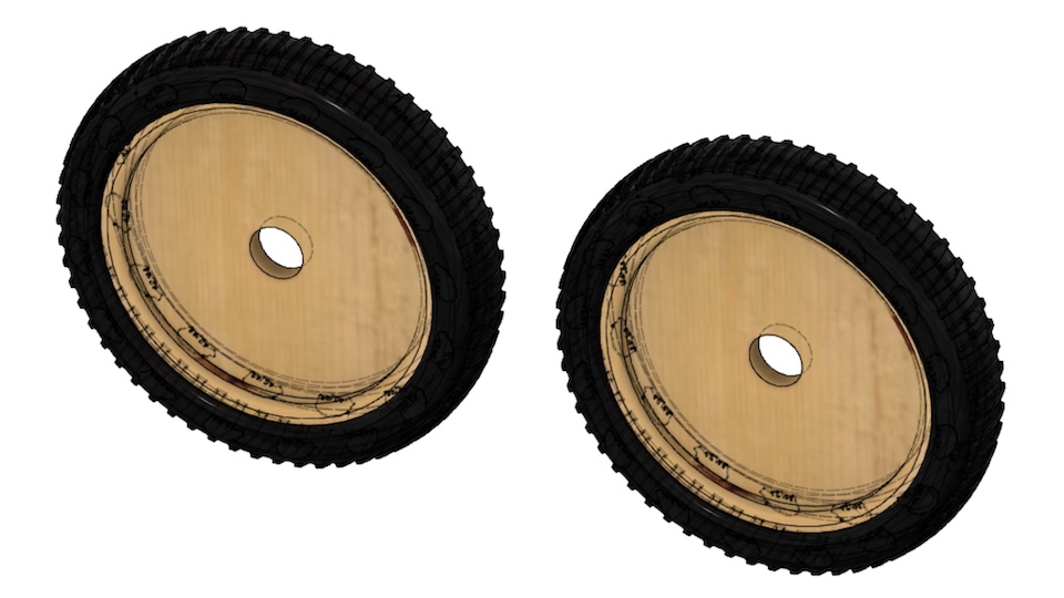
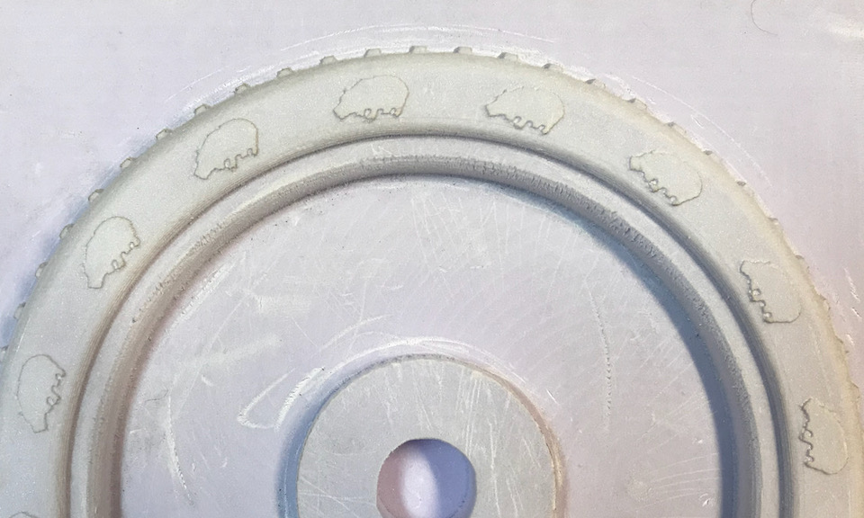
For the finishing touch I want to give the balance bike real rubber tyres. And of course with a tough off road like profile and hippos on the side. I made a designe in fusion and imported them into the assembly of the bike. The design looks smashing, so that’s a start.
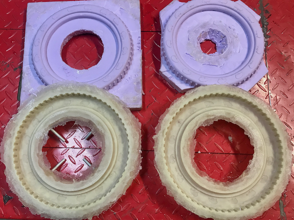
Test Mould
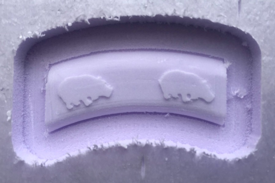
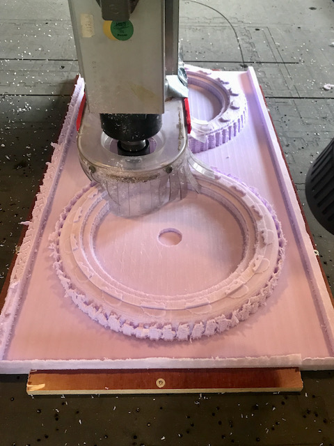
The idea is to make moulds from epoxy composite that I can clamp on the outside of the wooden rim of the wheels. Inside these moulds I will inject the K-flex rubber I used in the casting and moulding week. In that week I experienced that the details of the hippo were too tiny, even for a milling bit of 1 mm. To check how it worked with a bigger design I created a cut out and tried to mill that on the shopbot. The result is not fabulous, but I decided it was good enough. Later I might 3D print a paint stamping tool to fill in more details.
Designing the Mould
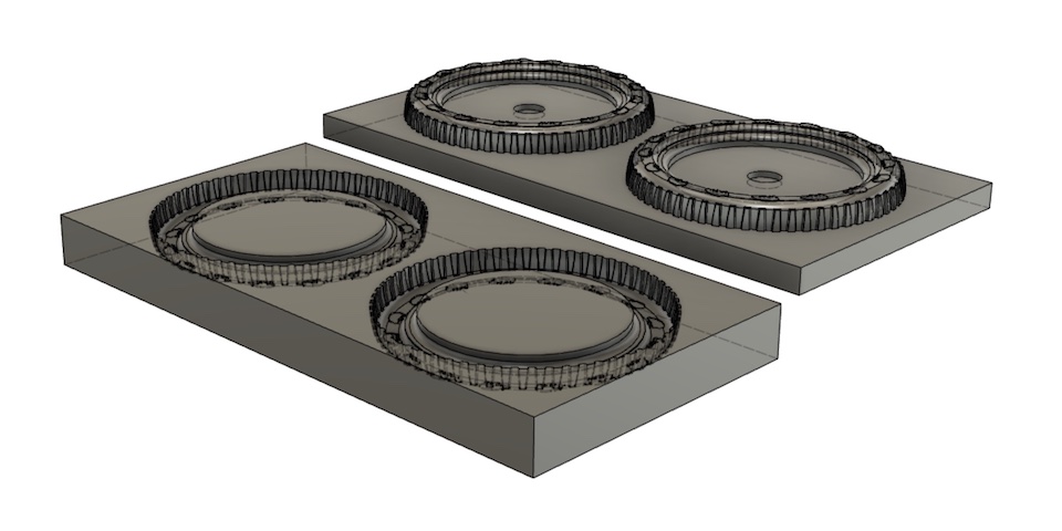
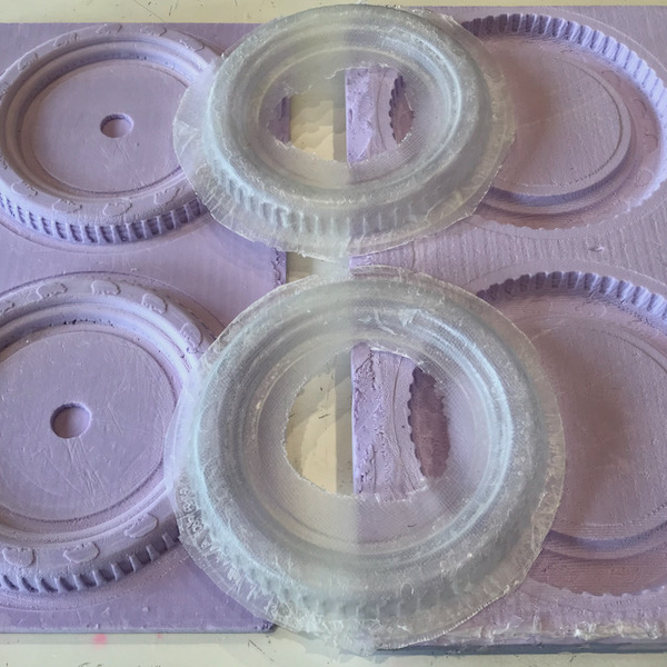
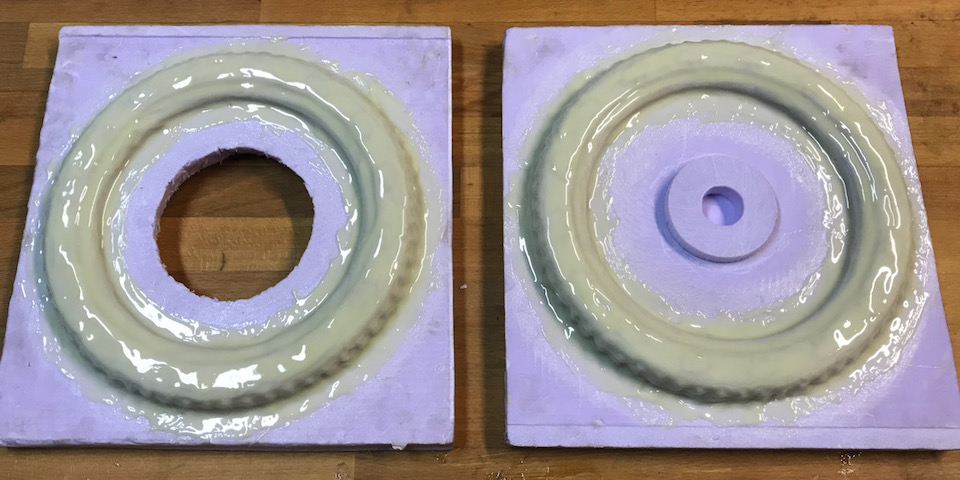
For the final moulds I exportes the tyres, wheels and rims to separate models. I removed all the unnecessary stuff like bearings and axles and turned them into two separate moulds for each side, because I wanted the hippos to run in the same direction. Based on my experience with epoxy and glass fiber I expect to run into problems to get the composite deep enough into the corners of the mould, so I decided to make a counter mould. Below are some screenshots.
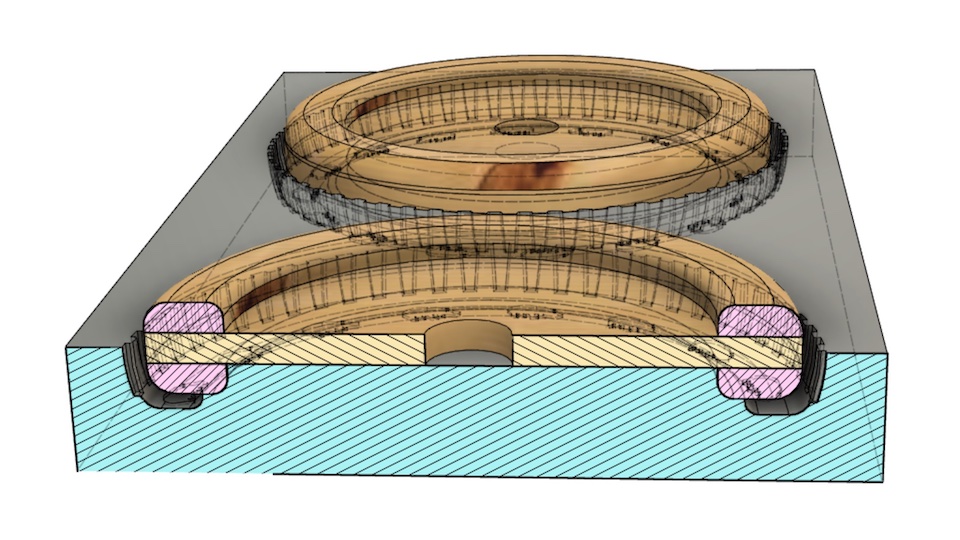
In the cross section below you can see the intended gap that will be filled when casting the rubber.
Making the Mould
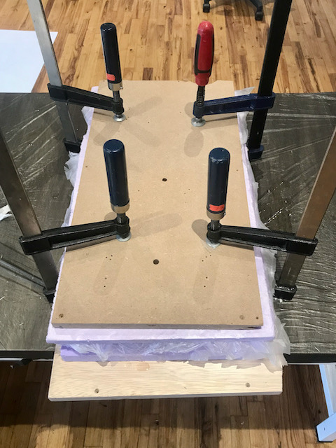
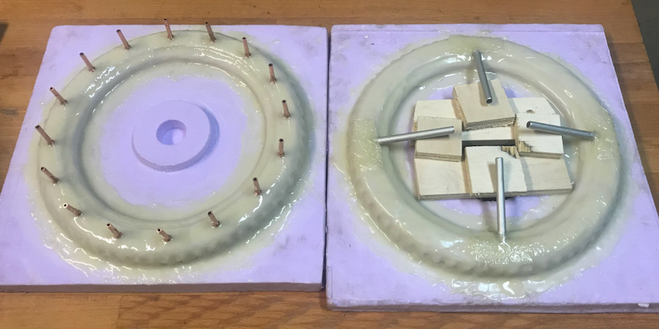
Using the positive to create a negative version is easy, but after that I had to create an offset to give room for the layers of composite material. It’s not hard in fusion, but I ended up with a quite complicated design that has a lot of different faces. To make counter moulds for 4 positives would cost me hours in tweaking. So I took the lazy approach. The mould material is made out of foam, so there are no large forces involved. I will create a toolpath for a 1 mm bit and mill it eventually with a 3 mm bit. This will give room at the sides and the height is adjustable anyway.
| milling the positive mould | clamped moulds after epoxy |
|---|---|
 |
 |
| all moulds | detail of the mould |
 |
 |
First Casting
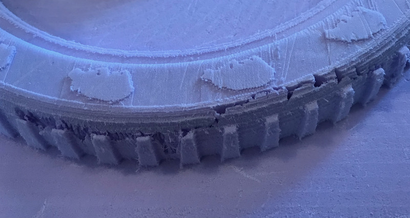
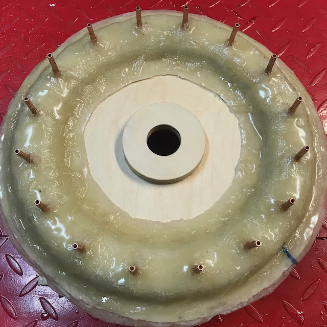
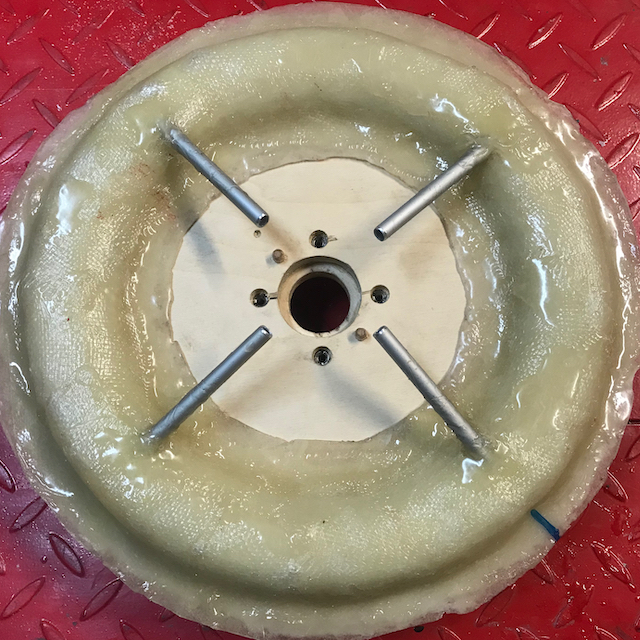
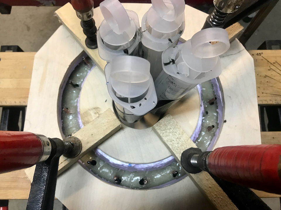
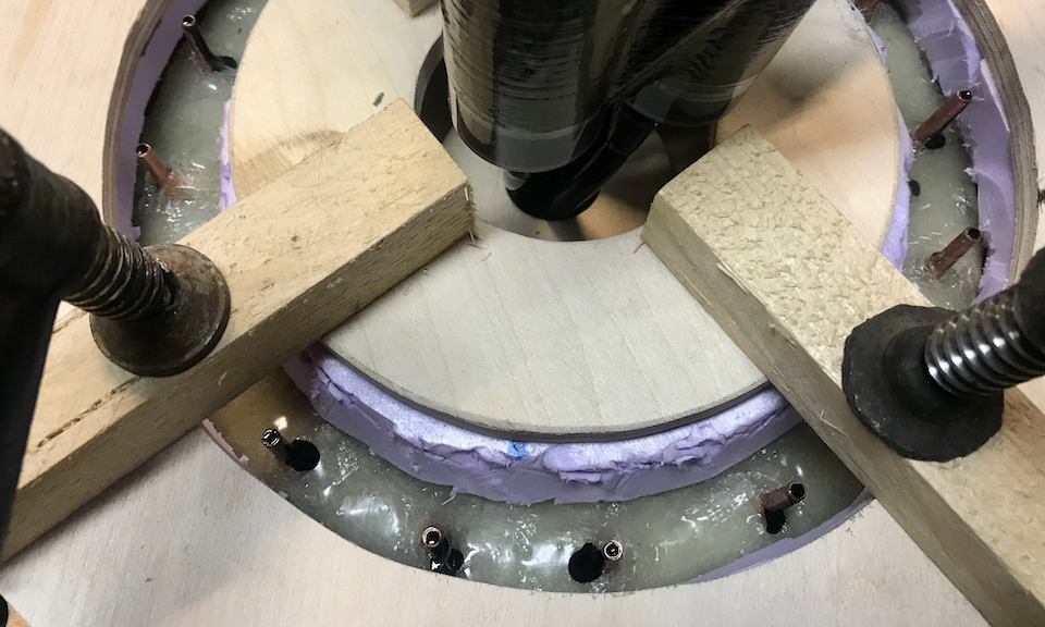
The first casting was based on my small test tyre in the moulding aand casting week. The learning was, that the mould wasn’t completely filled, so I bought big syringes to press the rubber in. I modified the epoxy moulds by adding runners made of aluminium pipes and down sprues from silicone tubes. The syringes fit on these tubes, so I started casting with KX-flex 60. From fusion I knew that the volume of the tyre was around 0,45 l, so I prepared a little extra and made 0,6 l mixed part A and B. Pot life was specified as 2,5 minute, which is short, but doable as I experienced with the little test tyre. But no, it wasn’t! after pouring the rubber into the syringes, which took less than half a minute, I tried to push the first syringe and it barely moved. The other ones where stuck too. The material was already too cured to push into the mould.
| runners in the bottom mould | clamped around the wheel with the tubes added |
|---|---|
 |
 |
| after pouring into syringes | result: casted syringes |
 |
 |
Learnings and 2nd Casting
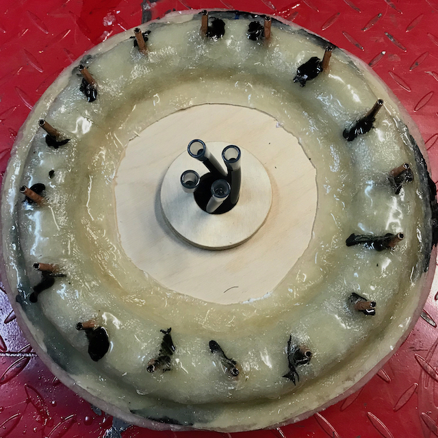
To understand what went wrong here I turned to our local vendor Form-X. Should have done that before I started, that’s learning 1. :-P In hindsight the story is logical. KX-flex is a urethane rubber, that cures with an exothermic reaction. The pot life should specify the amount that it’s valid for. With large qualtities the produced heat will speed up the proces and shorten the pot life. They recommended an other rubber called Formlastic 60. Alternative Vytaflex 60 would probably work as well. Pot life is 40 minutes aand the only downside is that its viscosity is a bit higher. But with the syringes I managed to push the mixed rubber into the mould, but I did need some force.
| result side 1 | result side 2 |
|---|---|
 |
 |
The top side is suffering from some air bubbles that got trapped. I drilled small vent holes, but apparently not enough. So this is an improvement point when I do the front tyre.
What I also learned from the man from FormX is that the epoxy we used for the mould is not the right choice for glassfiber reinforced moulds. This material, .... is used for thin layers of encapsulation, e.g. if you want to protect a PCB against moisture. In his opinion one should first brush two layers of gel coat on the positive to capture the details and when it’s still just a bit sticky add 4 to 6 layers of galsfiber with epoxy of type … So that’s the second improvement to add for the front tyre.
But the bike looks fine for now. I also had the seat covered with a piece of black imitation leather. Good enough to show during the final presentation.
Design Files
Design files in Fusion are to big for this repo, so here are the STLs of the mould and te counter mould.
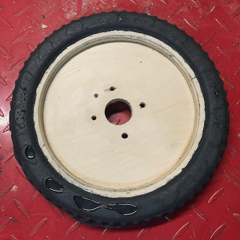
Front Wheel
Well, now the front wheel tyre has its turn. I already milled the counter mould, but with the new information about how to make the epoxy glassfiber reinforced mould I don’t need it. That is, for making the mould, but for support during clamping during the casting it will prove useful. Here I also used fusion to generate the G-code for the shopbot. Below a picture what it looks like.
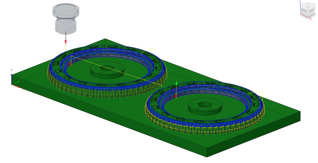
Milling the Mould
The rough cut was done fast and smothly using a 6 mm end mill. Then came the first finish and something strange happened. It took me some frustration, investigation and an estimated guess to find out what was wrong. When the program started it didn’t drive the Z-axis. The coordinates in the program changed, but the spindle didn’t move up and down. Comparing the G-code from the different runs first didn’t give a clue. They didn’t seem wrong or even different. At some point I noticed the only big difference was the line with the tool number. The working programs had a tool number of 1 and 5 and the faulty one had tool 23 (see line 11 of the code below).
 ' 1002
 ' front wheel pos mould
 SA
 CN, 90
 IF %(25)=0 THEN GOTO UNIT_ERROR
 &PWMaterial = 50
 &PWZorigin = Part Surface

 ' Contour1
 C7
 &Tool = 23
 C9
 TR, 10000
 C6
 PAUSE 2
 JZ, 65
 J2, 22.411, 154.777
 MS, 15, 8.333
 J3, 22.411, 154.777, 65
 J3, 22.411, 154.777, 45.197
 M3, 22.411, 154.777, 42.2
Just trying a lucky hunch I changed 23 into 3 and that worked! Apparently the shopbot program we use at Waag gets fucked up by a toolnumber of 2 digits. We should try later what the exact conditions are, but for now this works. pffft…
Unfortunately in this investigation an accident happened. Because of a faulty Z-axis the positive mould was torn by the milling bit. Luckily it wasn’t wood I was milling, so no machine damage or worse, peronal injury was caused. I think I can repar it and went on with the next milling runs.
But eventually I decided to re-do one half mould, because I discovered a flaw in the 3D model. I want the hippo’s on both sides of the wheel in the same direction and apparently forgot to mirror it for th front wheel. I found a nice new circular milling strategy in Fusion too, so this last one is the best result so far.
Making the Mould
For the mould of the front tyre I’m going to use a different material. First I wll apply gel coat, Smooth-On EpoxAcoat, and for laminating I will use Epoxamite. They are especially for moulds like this. The EpoxAcoat will capture the details and the glass fiber reinforced Epoxamite wil give it strength. Because the model is made of styrene foame, I didn’t want to use release agent spray, so instead I used vaseline to cover up a bit the small cracks in the material.
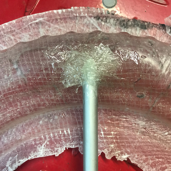
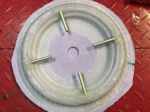
When the gel coat is still soft, I added vents and runners and used a two component epoxy glue to make sure they will stay in place. The vents were made of brake line tube of 4,75 mm with trumpet ends that are made with a special tool for making conections in car brake lines. The runners are made of 8 mm aluminium tube. In the rear wheel casting I ended up having trapped bubbles on the top side of the tyre, so now I used one vent on every hippo.
The total has now about five layers: 2 gel coat layers, 2 glass fiber layers and one glass cloth (woven material) layer. Removing the moulds from the model was a bit difficult and I had to use quite a bit of force. But with this amount of layers it’s strong enough. Both on the outside and on the inside I used a Fein multitool to cut off the fibers and rough parts sticking out.
| applied gel coat |
|---|
 |
| added runners and vents |
 |
| finished mould |
 |
Casting Rubber
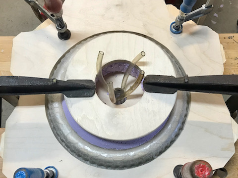
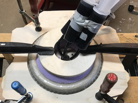
Now the casting process can start. First stage is assembling the moulds with the wheel in between. Then adding tubes, syringes and clamp the whole assembly together. This time I used an other type of urethane rubber, because I wasn’t satisfied with the colour of the Formlastic I used for the rear tyre. It continued to appear grey, no matter how much black colourant I added. So again by recommendation of the company FormX, I turned to vytaflex 60.
| mould assy top side (vents) | mould assy down side (runners) |
|---|---|
 |
 |
| clamped mould (after casting) | clamped mould detail |
 |
 |
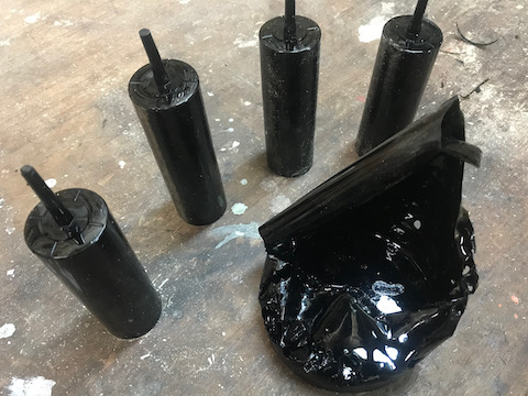
| mould assy after casting | opening the mould |
 |
 |
| casting rough | casting after cleaning |
 |
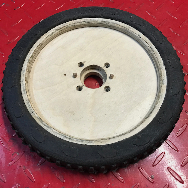 |
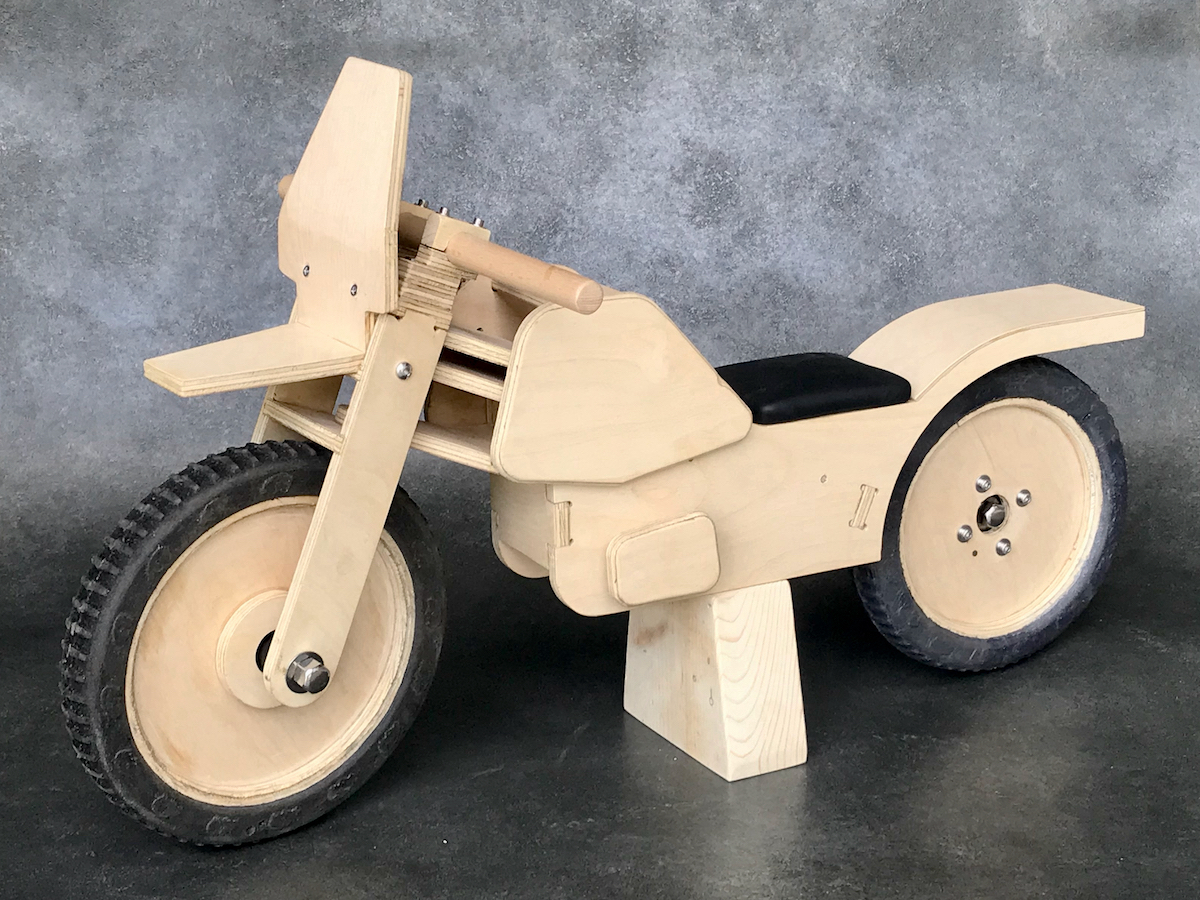
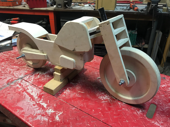
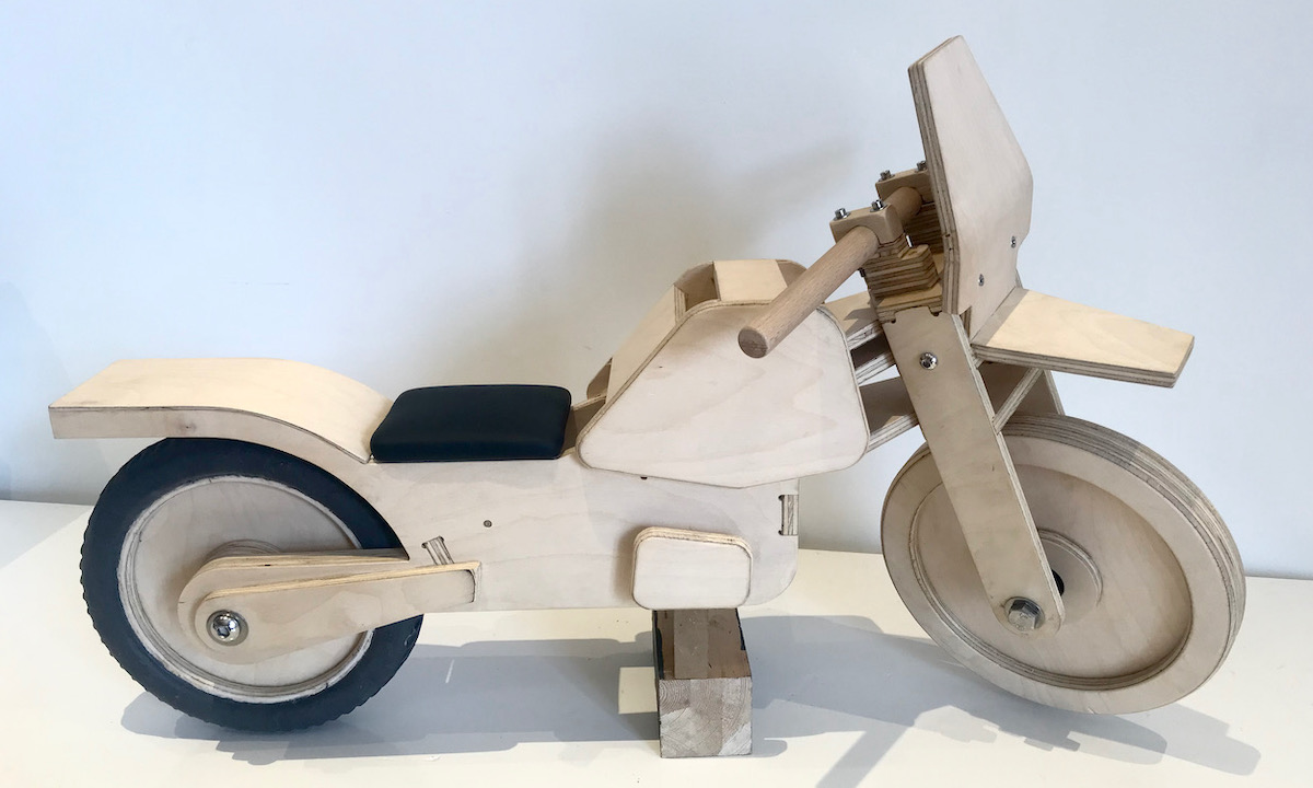
Final Result
No words needed for this paragraph, the hero shot says it all.