2,5D Machining: ShopBot
The ShopBot is a powerful machine. Making mistakes can be very dangerous, so Henk ordered us not to, and he is absolutely right. I’m used to working with machinery and have been using metal milling machines and lathes, but only hand operated ones. In CNC you have to plan ahead and check and double check if your program has any mistakes. Certainly for a new machine it’s necessary to let someone else review your toolpaths.
Group Assignment
After the instruction we did some investigations in the behaviour of the machine. I wanted to have look on the effect on dimensions of climb and conventional milling. When I use my own milling machine I seldom use climb milling, because it’s very difficult to control the movement of the hand held machine or when it’s table mounted, to keep in control of the material.
As a mechanical engineer I know the dis- and advantages of both and also that climb milling tends to drift away from the cutting line and conventional tends to drift towards the cutting line. I made in VCarve two simple squares of 100 mm and used the test set up from the instruction to try them out. They were milled on the outside and should measure exact 100 mm after milling.
The result was as I expected and as predicted in the previous paragraph. But I didn’t expect the difference to be this big:
- climb cutting: the square was 100,6 mm (0,6 mm wider)
- conventional: the square was 99,4 mm (0,6 mm smaller)
The Shopbot seems less stiff than I would expect for milling with a 5 mm endmill in relatively soft material.
Balance Bike
For the individual assignment I designed a balance bike for my grandson. On this page I go into the details of working with Vcarve and the shopbot. But the balance bik itself eventually led to a whole project of its own, so I made a special page for that in the projects section.
VCarve
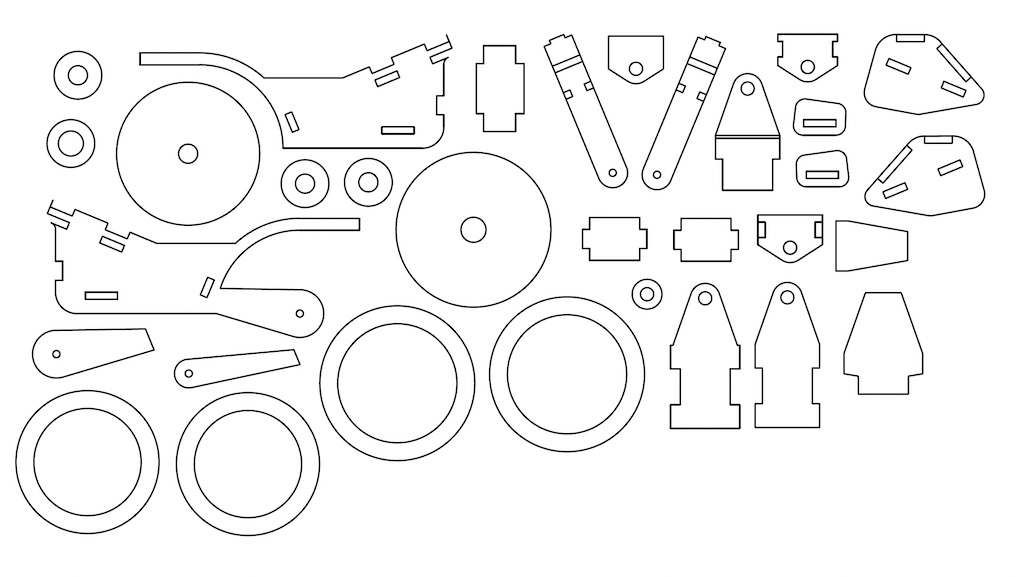
First step for the shopbot is to crteate Gcode. That is possible by importing DXF, DWG or PDF in VCarve. As recommended by Michelle I used DXF. This seemed to work perfect and I just did a quick rearrangement to do a bit of manual nesting.
What I also did was a new check of the dimensions with offset for the climb milling. I made 2 rectangles again, this time 80 mm and milled them on the outside with -0,2 and -0,3 mm offset. It turned out that I really needed -0,3 mm offste, but this depended on the direction. In X direction this offset was perfect, but in Y it even wasn’t enough. Unfortunately there’s no separate setting, so I left it at -0,3.
The export turned out not that good. To make a good toolpath VCarve needs closed vectors. The export from Fusion had lots of flaws. There were double lines, closed vectors at the wrong place, or not closed at all. Simple forms like the wheels were no problem, but when pockets coincided with profiles there were big problems. Sometimes they were even difficult to find and if I could keep reference points I sometimes just deleted lines and drew them again fresh.
VCarve has a nice feature of automatic T-bone and dog-bone fillets, which is much faster than doing it in Fusion. But with applying this tool I discovered even more flaws, because some corners the tool just didn’t understand. This was in the end my result in the 3D toolpath simulation view:
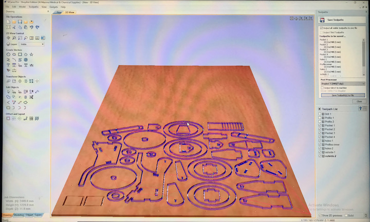
To summarise my VCarve learnings and general guidelines:
- Make sure your vectors are correct and closed
- some exports have double lines, vectors closed in the wrong path or not visible open ends
- correct them in VCarve by using the “close” tool
- The Z-level is zero on the top of the sacrificial layer
- Make sure you set the right material thickness and safe Z-level (thickness + > 6 mm)
- Include in VCarve the locations where you want to screw your material on to the sacrificial layer
- make drill holes on these spots with only a couple of mm depth in cutting
- make a separate file for those drill holes, you need to screw the material before the “real” job
- For the profile cuts, use tabs:
- use them about every 200 mm length or one on each side
- take into acount the grain of the material; tabs in side parallel to the grain have less strength
- take into account the size of the cut out; a piece of 30 mm or less can break loose and get catapulted out by the milling bit.
- Make sure the rest of the toolpaths is in the right sequence:
- first drill holes
- then pockets
- then inner cuts
- finally outside cuts
- Export your design to VCarve to generate the G-code for the ShopBot
Safety First
I’ve made pictures of the steps you need to take to operate the machine and made notes for steps I’m not yet familiar with. But safety first!
- Make sure there’s always someone else around when you operate the ShopBot
- Check if the machine is completely free and that there’s no debris or tools on the machine
- Check if the suction installation is working properly and switch it on before you start milling
- Notify people around that the machine is going to start and make sure they stay away from it
- If something unexpected occurs:
- first hit the space bar to pause the machine if a spinning spindle is not a problem
- if it’s a real emergency hit the emergency button on the right side of the machine
- if you notice sparks during milling:
- stop the machine immediately
- run to the dust collection system and ope it to check for burning smell
- in case of fire, use the fire extinguisher that’s in the pathway to the dust collection
- even if you don’t smell anything, remove the bag, seal it and get it outside
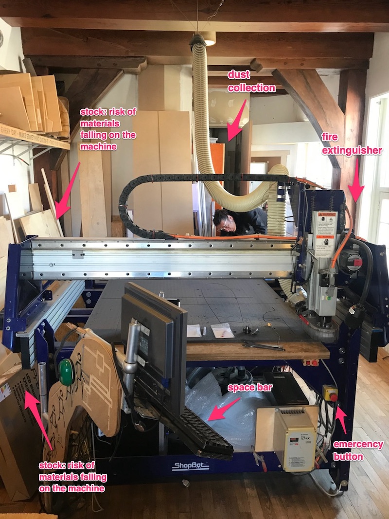
Below is a picture of the room with the ShopBot and with markes safety items.
Operating the machine
How the machine mechanically works is familiar to me. I know the X, Y and Z, how a collet woks and how to change a milling bit.
VCarve runs on several computers at De Waag, so after finishing it needs to be loaded on the ShopBot computer with a USB stick. So now we can start the machine. On the ShopBot the sequence is:
- home the machine in X and Y
- move it manually by hitting the “K” button (arrows and pgUP and pg DN)
- move it to a spot where your material will be
- check if the Z-level detector works
- perform the Z-leveling
- move it up manually and remove the contact plate
- move it away to make room for your material
- move it to your the home pasition of your material manually (job home)
- take a picture of the position of job home relative to the machine home
- start the drill patern for the screws
- this doesn’t work for small size materials
- in that case there’s risk your material will move when drilling
- move the machine manually away from your material
- drill screws in the marked spots
- start your milling job
- for safety keep your hand near the space bar to stop in case something happens
- after milling, move the machine away again
- unscrew your material
- make sure there are no screws left behind
- clean the bed with the vacuum cleaner
For the basic settings I made a separate section on the overview page, so I can find them easily later. You can find it in the ShopBot settings.
Results
The assembly is also quite time consuming. Because of the inaccuracy of the fit holes, I have to do a lot of post-processing. Sometimes I also forgot to include some features. Like for the wheel, I should have included drill holes for the dowels to connect the rims. Now I had to do that by hand. BTW: I used the fillet milling bit in my workshop to change the appearance of some parts.
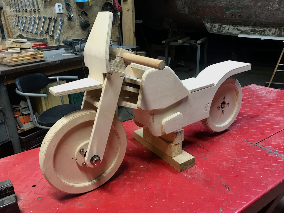
Reactions on the result are very positive. Some say I should make a business out of this. What I might do if I have some time, is to document the whole thing a bit more in detail with all the fabrication files and make it available for anyone who wants to make a copy or an adapted version. Please go to the balance bike page for the full story.
3D Machining
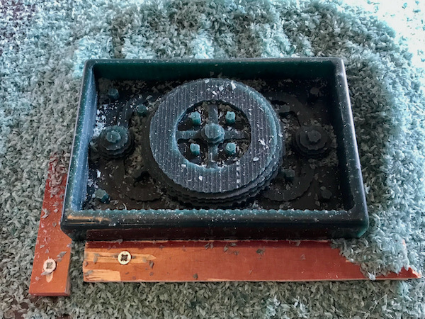
For the Moulding and Casting week we had to mill the positive model to cast the mould from. Details about the design can be found on that page.
For the machining part there are no real difficulties. VCarve is familiar by now and I know how to change tooling and to level the machine. For the attachment of the wax blok to the sacrificial layer we use duoble sided adhesive tape and a wooden support on all four sides to prevent movement in X and Y directions (see pictures below). For the settings – see basics on ShopBot settings page – I used a low speed of 10 mm/s to reduce the effect of the shock wave that occurs due to absence of deceleration of the ShopBot axis drivers.
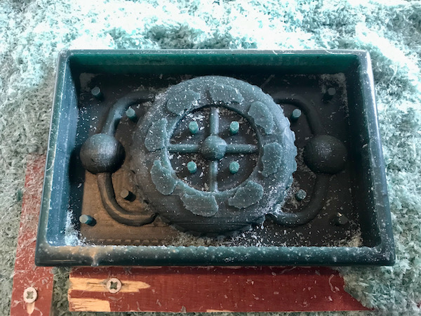
| positive mould rough cut | positive mould finish |
|---|---|
 |
 |
There were some noteworthy learnings however:
- When leveling in Z, the machine moves down to the contact plate and immediatelu releases from the contact again. If the contact plate is not firmly pushed to the surface the contact will persist and the machine will give an error.
- The surface of the wax block is very wobbely before the first milling. After the rough cut the zero of the surface will change. I solved it by moving the spindle back to the origin and measuring the gap with a makeshift feeler gauge and used that between the contact plate and the surface for the leveling after the tool bit change. But a better way is to make flatten the top of the block first and to do an extra Z-leveling.
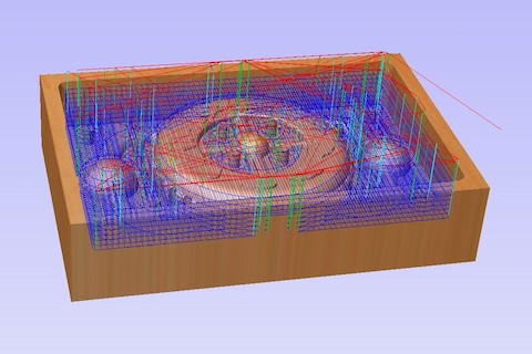
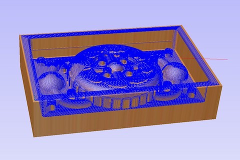
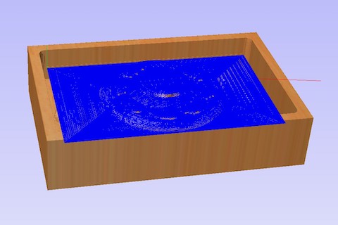
For the rough cut I used a 4 mm milling bit and for the finish I used a 3 mm one. Because the features of the hippo are very small I decided to make a superfinish toolpath with a 1 mm milling bit for just the hippo parts. It is probably also possible to select parts in VCarve for this toolpath, but it took me too long to figure out how. Therefore I just made a new model for the superfinish that avoided interference with the lower parts of the model. This is necessary because the shaft of this milling bit is 3 mm and would collide with the sides if it would plunge deeper than 10 mm into a vertical wall. Below are the pictures of the toolpaths.
| rough cut | first finish | superfinish |
|---|---|---|
 |
 |
 |
My final learnig was that even the 1 mm bit was too big for the tiny features, so after 10 % of the milling job I decided to abort it. For this test model I will keep just the “ghost-like” hippos. For the final version I might do in the wild card week I have to make sure the hippo design meets the dimensions of the milling bit.
For the rest of the process, please got to: