Noise Drum (final project)
For now, let’s assume my final project will be about making a noise drum. As already mentioned, the main goal was to learn about systems that are part of electric vehicles. The first draft can be found on the introduction page of my Projects section.
In preparation for the final design I started using the weekly assignments to do some experiments and research for the sub-systems I need. One of the main ones is the motor driver. I wanted to learn how a Variable Frequency Driver (VFD) works by designing one for my drum drive. In the end I didn’t manage to get it working and used a simple DC-motor driver. But I have done a lot of research and documented that on the input and output devices page.
Components, Requirements and Calculations
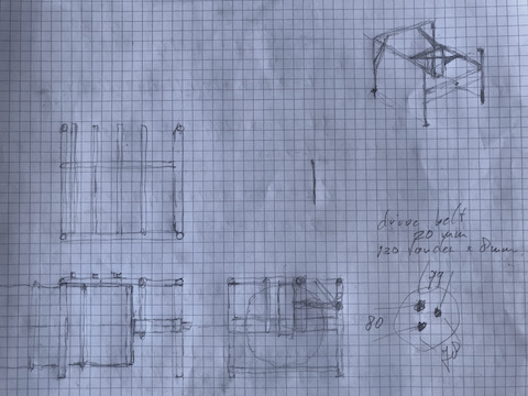
Based on the first sketches I made this PBS (product breakdown structure).
- Drum
- Drum Axle
- Drum - made from 60 l oil drum
- Noise Rings - on the outside of the drum
- Horn - from composites or from steel plate welded on the open end of the drum
- Drum Drive
- Motor Driver - power board with mosfets and gate drivers
- AC Motor - probably a large BLDC motor
- Coupling - 3D printed flexible coupling from motor shaft to drum axle
- Noise Drives
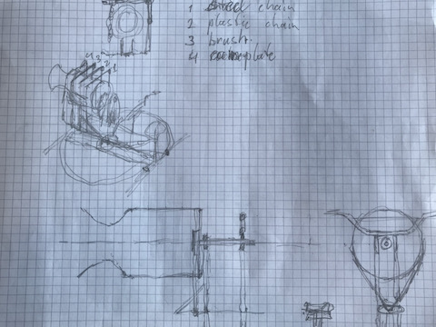
- Noise Chains - to produce different sounds
- Metal Chain
- Plastic Chain
- Brush “Chain”
- … something else
- Links - construction to drive the chains towards the drum and back
- Servos - to drive the links
- Control
- Motor Controller - 6 outputs: PWM
- Speed Control Handle - 1 input: 1~3 V
- Noise Controller - 4 outputs: PWM
- Noise Selector - 4 inputs: TBD
- Central Control Unit - probably all above combined in one board with SAMD21 or SAMD51
- Battery
- Batteries - depending on the voltage level needed for the drum motor
- BMS - optional: battery management system
- Frame
- Basic Frame
- Secondary Frame
- Control Unit Plate
- Drum & Motor Support
- Chain Frame
- Handle Bar
- Seat
I will try to use as much left over materials as possible. I have alot of junk in my workshop. I probably don’t have to buy any material for the construction of the frame and I have enough bearings and bolts and nuts too.
Requirement Notes
Some general design considerations:
- drum torque:
- drum radius ≈ 200 mm
- chain force ≈ 10 N
- torque ≈ 2 Nm
- with 5 noise chains torque ≈ 10 Nm
- motor torque:
- reduction gear: 1 / 50
- torque: 0,2 Nm
- power estimation:
- max drum speed: 2 Hz (120 rpm)
- angular speed ω ≈ 12,6 rad/s
- P ≈ 126 W, calculate with Pmax = 150 W
Some basic requirements for the microcontroller:
- PWM pins motor - 6
- ADC input pins throttle handle - 2
- analogue inputs sound control - 4 (or less, depending on final choices of chains)
- analog outputs sound control - 4 (or less, depending on final choices of chains)
- I2C output to LCD or OLED - 1 (2 pins)
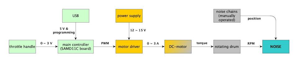
Block Diagram
For better understanding I drew a block diagram that shows how the main functions work together.
Final BOM
In the end I had to change my plan because I didn’t get the 3 phase driver running. The last week I quickly turned one of the older versions into a single mosfet driver board suitable for a DC motor. The final list of ccomponents and the part structure is captured below:
- Drum
- Drum - made from 60 l oil drum
- Axle
- Inner disk
- Outer disk
- Spacer disk
- Pulley 64 T
- Retainer
- Spacer shims
- Bearing adaptor ring 22 x 25 x 11 mm - 4 pcs
- Bearing retainer tube
- Mounting tube
- Bolt M8 x 12 with ring
- Bolt M8 x 70 with rings and nuts - 3 pcs
- Drum Drive
- Motor driver board
- Gate driver IR2112
- Mosfet IRF540N
- Capacitor 1 µF
- Capacitor 300 nF
- Resistor 5 Ω
- Connector 2 x 2 vertical
- Connector 1 x 2 horizontal - 2 pcs
- Motor assembly
- DC Motor MTI Torque Systems 2105
- Pulley 12 T
- Motor base plate
- Motor back plate
- Motor clamping plate
- Screw M6 x 70 with washer and wing nut - 2 pcs
- Drive belt - SKF TB01120 - 130T x 20 mm
- Noise Drives
- Grinding Chain
- Rectangular tube 25 x 25 mm - 100 mm
- Sanding tape - 400 mm
- Duct tape
- Metal Chain
- Rectangular tube 25 x 25 mm - 100 mm
- Anchor chain - 400 mm
- Wood Chain
- Rectangular tube 25 x 25 mm - 100 mm
- Plywood 12 mm - 200 x 25 mm
- Piece of rope
- Control
- Motor controller
- Throttle handle
- Hall sensor 1: 0.89 ~ 3.84 V (not used)
- Hall sensor 2: 0.44 ~ 1.91 V
- Power supply wire 2 leads
- Connector band wire 4 leads
- Frame Assembly
- Frame
- Legs pipe 1” - 4 pcs
- Connection beams 3/4” and 1”
- Chain gliders 20 x 20 mm - 3 pcs
- U channel steel 70 x 40 mm - 700 mm
- Nut high M8 - 2 pcs
- Bearing housing with rim
- Bearing housing with axial degree of freedom
- Bearing 6205ZZ - 2 pcs
- Screws M6 x 25 with washer and nut - 4 pcs
- Screws M6 x 30 with washer and nut - 4 pcs
- Handle Bar
- Handle bar mounting blocks - 2 pcs
- Socket head screw M8 x 40 - 4 pcs
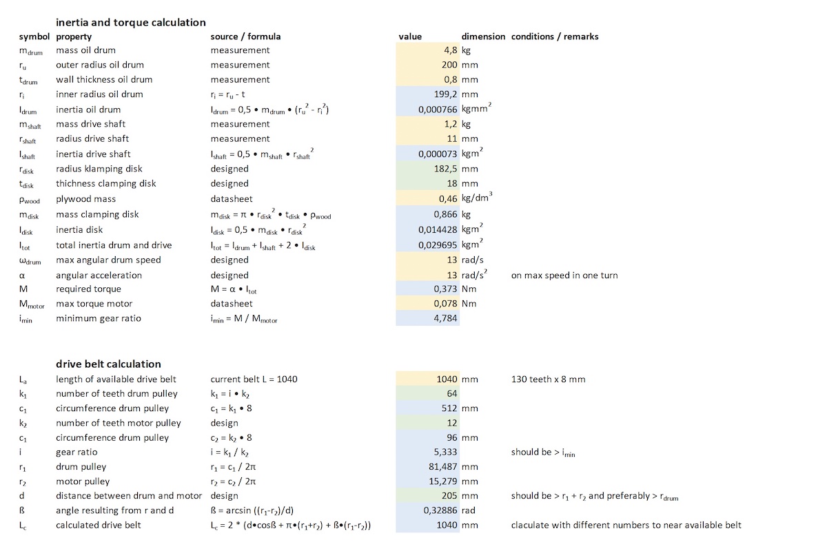
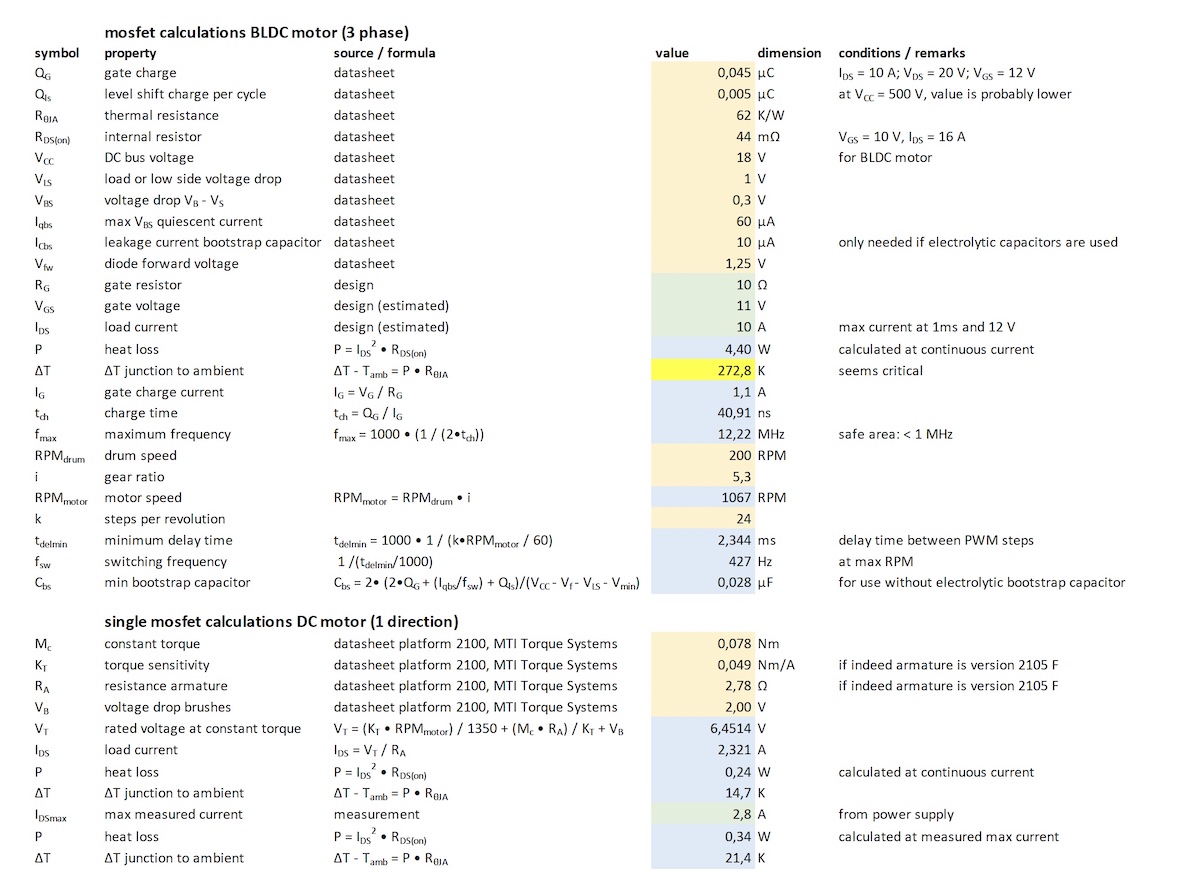
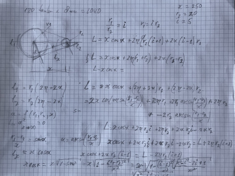
Calculations
For determining dimensions and estimate power consumption and heat dissipation I made some calculations in excel. The first sheet is related to mostly mechanical calculations and the second sheet deals with electronics. All yellow fields are fixed inputs from datasheets or fixed values components that I used. All green fields are estimated or design decisions from my side. The blue fields are resulting calculations from the other fields as input.
Assignment Week 17
The final project proposal should answer the following questions:
- What will it do?
- It will make noise by a clatter of chains against a speed controlled revolving oil drum
- Who’s done what beforehand?
- Nothing identical as far as I know, but the inspiration comes from mechanical art projects like Jean Tingelay
- What will you design?
- AC-motor controller board
- servo control board(s)
- central control unit
- drum construction and bearing
- steel support construction incl. seat and handle bar
- What materials and components will be used?
- a metal oil drum
- 2 left over bearings type 6205ZZ
- steel construction parts from leftovers
- a left over motorbike handle bar
- a BMW ride by wire throttle control handle
- a dedicated motor driver with 3 gate drivers and 6 mosfets
- a brushless DC motor used as 3 phase AC motor
- one or more servo motors
- steel and plastic chains
- a steel brush
- a control unit based on the SAMD family
- optional: I2C display
- Where will they come from?
- a lot from left overs in my own workshop
- electronics from Waag or local vendor Conrad
- BLDC motor from de Waag
- How much will they cost?
- practically no cost involved except some components like mosfets and gate drivers
- What parts and systems will be made?
- see above
- What processes will be used?
- welding
- 3D printing
- PCB milling
- shopbot 2,5D milling
- Arduino IDE programming
- What questions need to be answered?
- main question still is to get the 3 half bridges working
- How will it be evaluated?
- my central focus of fabacademy is to understand AC motor control, so if I’m not able to eventually construct a speed controlled device that reacts on the input of the throttle handle, I fail in my opinion.
Drum
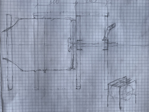
For the dum I bought a second hand oil barrel of 60 l. I removed one of the lids to make it open on one side. In order to create bumps, I hammered the circomference of the drum from the inside. This made dents that poke out on the outside wich will cause the chains to rattle.
For the shaft I used an old rear axle drive shaft from a van. The sheet metal is very thin, so in order to make it more rigid I made two disks that are mounted on both sides of one of the lids of the barrel. With the shopbot I cut them from 18 mm plywood which ensures that the hole for the shaft is exactly in the middle. I had to enlarge the hole of the inside one, because the shaft isn’t exactly 22 mm up to the base. To mount the shaft exactly perpendicular I used shims under the connecting three lips.
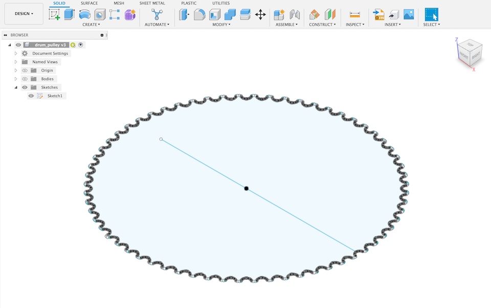
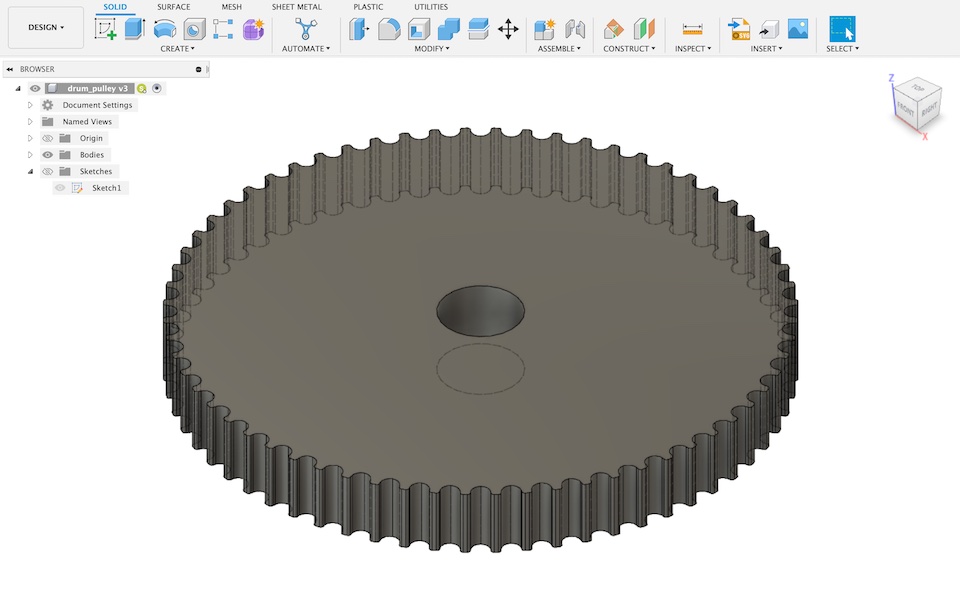
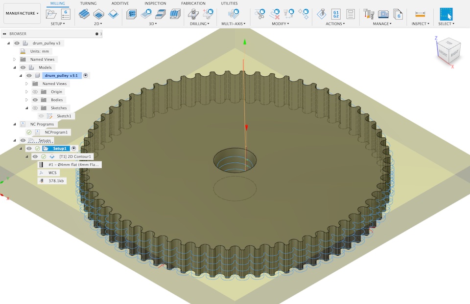
Drum Pulley
The pulley I used was based on an old SKF drive belt from a car cooling system I found which is 20 mm wide. Because the only plywood availbale was 18 mm thick I used a spacer of 3 mm on the inside towards the drum and a retainer disk on the outside. The amount of force is limited, so a pulley of 18 mm is strong enough.
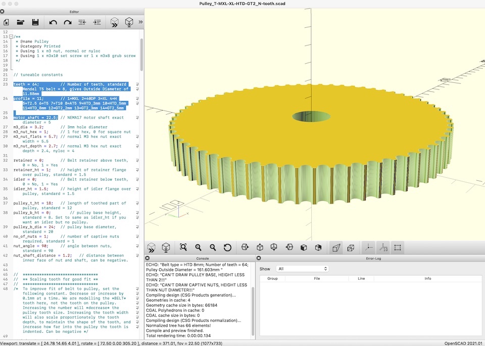
For easy construction I wanted to place the motor outside the drum. With a calculated ratio that should be around 5 or higher (see above) this limits the choices of pulley teeth number. The drive belt had a pitch of 8 mm, so I just made a hunch that the pulley generator in OpenSCAD from thingiverse would produce something useful.
I used the HTD 8 mm type and that worked, but to make the big drum pulley on the shopbot I had to use a work around. Within OpenSCAD I wasn’t able to find a quick way to export a 2D vector file to import in Vcarve. After consulting others at de Waag I eventually decided to just import it into Fusion and make a sketch based on the generated pulley. I turned that into a model aand used the manufacturing environment to generate the Gcode. BTW: I prefer Fusion to Vcarve for that anyway; it has far more different toolpath strategies.
| OpenSCAD | Fusion Sketch |
|---|---|
 |
 |
| Fusion model | Fusion toolpath |
 |
 |
Drum Drive
In the junk in my workshop I also had an old DC motor that might work for this application. I did some research on internet and found that it was made by Montevideo Technology Inc. They still make this type and the datasheet from the current version is probably not far off. The type I had was a small 2105 with a tachometer on the back end. It was still working and the brushes were still in good condition.
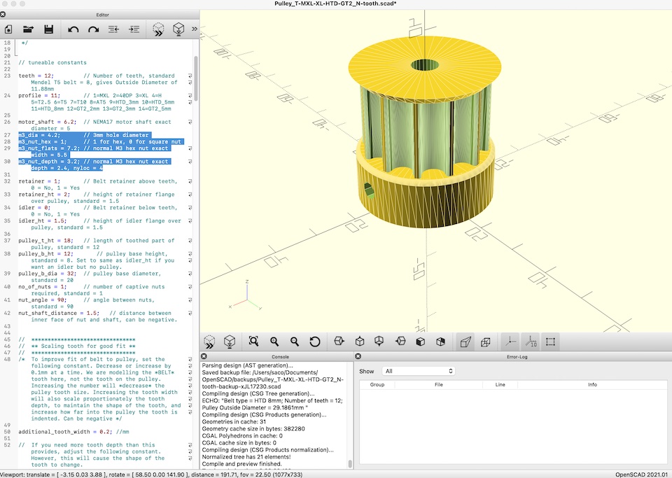
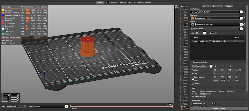
Motor Pulley
The pulley for the motor was small enough to print from an STL exported from the OpenSCAD pulley generator. Here I used a pulley base to screw it to the shaft of the motor, but 3 mm seemed a bit small, so I changed that to M4. Therefore I had to adjust the nut slot to the key width of 7 mm and nut thickness of 3.7 mm, of course with a bit extra for some play.
For generating Gcode I used PrusaSlicer with mostly the standard settings for PrusaPETG. In a previous project I experienced that the strength is sometimes not enough, so I used a different setting for the infill: a pattern of 3D honeycomb with a density of 25%.
| pulley in OpenSCAD | pulley in PrusaSlicer |
|---|---|
 |
 |
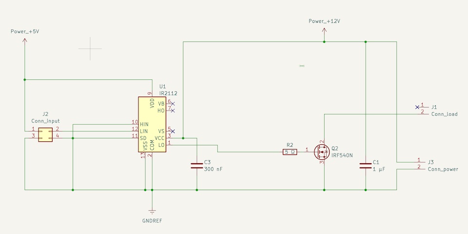
Motor Driver
The motor driver was a hacked version of the second version of my motor driver research (see the paragraph about that in the input&output section).
I removed the high side mosfet and the linked components and made sure on the gate driver the high input and the SD input of the gate driver were connected to ground. I decided to feed the logic of the gate driver with 5 V from the controller board. The schematics is in the picture below.
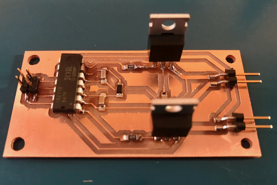
I re-used the original board, so to match the new set-up I had to make several patches.
| original board |
|---|
 |
| patched version |
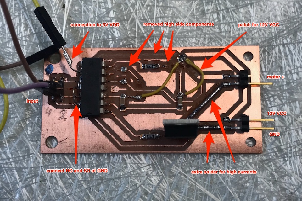 |
As you will see in the presentation video, I tested it first with a small solenoid to make sure the principle worked. The signal was very noise, but I had no time nor the components to add the right capacitors to reduce this.
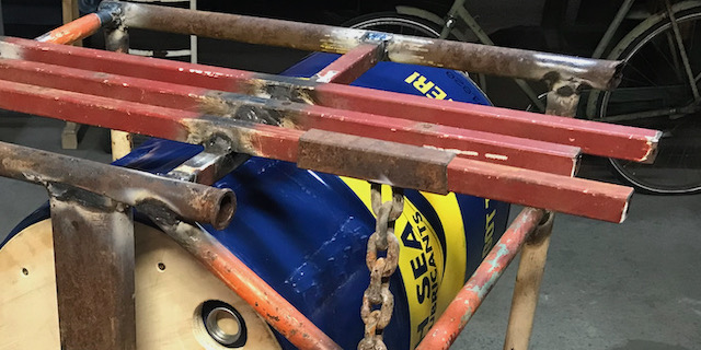
Frame Assembly
The frame was constructed from old material I had in my workshop Most of it is gas transport pipes and some parts are square tube 20 x 20 mm or 25 x 25 mm. For the mounting of the bearing housings I found a left over U-channel beam of 70 x 40 x 3 mm. The part I used near the drum was cut down to 70 x 25 x 3 mm because it needed some clearance from the drum mounting screws. The construction was not really carefully designed, but constructed based on some rudimentary sketches that actually look more like doodles and decisions on the go.
| some doodles | |
|---|---|
 |
 |
 |
 |
The bearings are two old 6205ZZ bearings (both side sealed) that are 25 mm on the inside and 52 on the outside. To fix them around the shaft I 3D printed 4 bushings. They are mounted to steel U profiles of 70 x 40 x 3 mm. The bearing housings are also a 3D print. One of them is closed, so one bearing has a fixed position and the other one is open to allow some play in the axis direction.
Noise Drives
To finish the noise drives was not possible anymore. Originally I wanted to use three servos with links to the chains so I could switch them on and off from the handle bar and control the amount of engagement. For now I just made the sliders from the square tubes and welded a chain to one of them and attached some wood and a strip from a sanding roll to the others.
Control
The control was quite simple. As mentioned before, I re-used my motor control board based on thye SAMD11C from the input & output devices week. I already knew the hall sensors from the throttle handle were working fine and that I could read the signal.
Only thing I had to add is to map the signal to the output PWM for the DC motor. I mapped it quite narrowly, because the motor only started running at a fair amount of current. To make sure the motor would stop when the handle was closed, I added a condition where the PWM output would be zero. The lines of code are just a few, as you can see below. The print commands were just for the initial check if the reading and the mapping of the sensor were correct.
// program for controlling DC motor single direction
// input comes from a throttle handle hall sensor

// definitions of output pins
// _dn is gate driver LIN
#define A_dn 5

// hall sesnro pin
#define hall_pin 2

int hall_val = 0;
int hall_map = 0;

void setup() {
// pinmode output to gate driver
pinMode(A_dn, OUTPUT);

// pinmode input from throttle handle
pinMode(hall_pin, INPUT);
Serial.begin(115200);
}

// testrun output
void loop() {
hall_val = analogRead(hall_pin);
Serial.println(hall_val);
hall_val = map(hall_val, 150, 1023, 150, 255);
Serial.println(hall_val);
hall_val = constrain(hall_val, 150, 255);
if (hall_val < 200) {
    analogWrite(A_dn, 0);
}
else {
    analogWrite(A_dn, hall_val);
}
delay(200);
}
Final Result
Design Files
Below you can find the links for downloading various design files:
Bearing Housing and Bushing in Fusion