Input & Output Devices
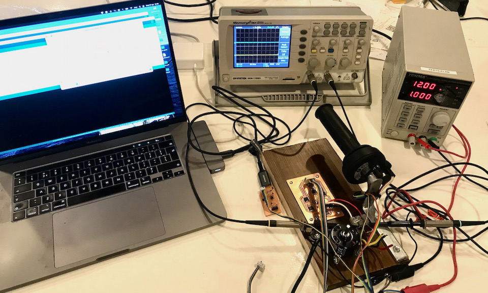
I combined the input and output devices into one page, because it is a preparation for my final project with similar set-up. Below thaere’s a picture of the test set-up with power supply and oscilloscope. I needed this to debug my output part, that wasn’t functioning right. More about that below in the output paragraph.
Motor Controller
The core of the system for my makeshift variable frequncy drive is the controller board. It should have an input to set the desired speed and an output to control the 3 phase moter based on that.
Motor Control Board
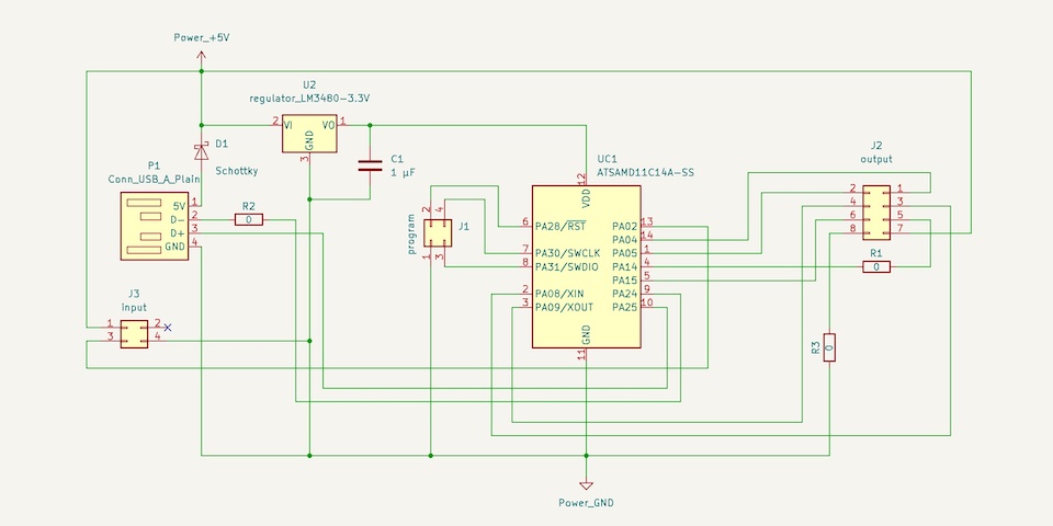
For the control board I used the SAMD11C. I needed at least 6 PWM outputs and at least 1 input to control the RPM of the motor. I also wanted to be able to directly communicate via USB. Below you can see the schematics with regulater USB protection with a diode and connectors for output, programming and input.
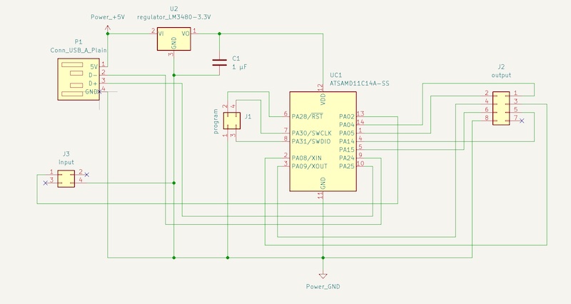
Later I made a patch to add 5V for the hall sensor (see below), which is now available on pin 3 of connector J3. For the final project I even made a second patch to make 5V also available on pin7 of J2.
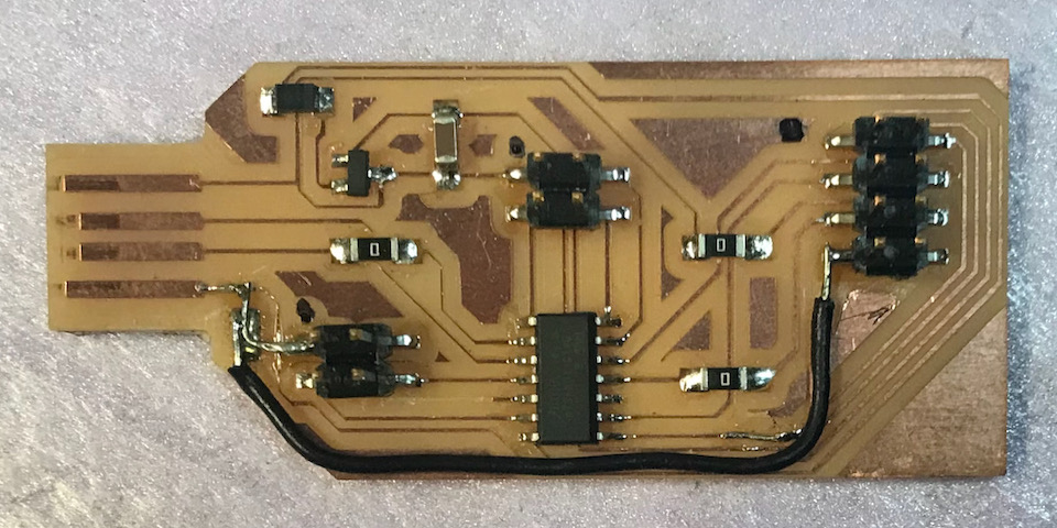
The final board doesn’t look fabulous, nut it works fine.
Throttle Control Handle
For the input device I wanted an electronic throttle control handle. Originally I wanted to make it from scratch, but I was lucky. The motor repair shop I visit regularly saved a throttle handle for me that had a faulty heating, but was still functioning. First action was to try to find a connector that fits on the pins inside. It’s of course special made for the bike and not available. But I managed to find connectors with the same pitch and was able to cut the plastics around it away just enough to fit into the slot.
But I didn’t know what kind of sensor it was. There’s no information available on-line about them. Some information stated that it should be a potentiometer, but measuring the resistence gave no results on any of the pins. Eventually I managed to open the casing and found a little magnet inside, giving a hint towards a Hall sensor. But why 6 pins than? Were they using some bus protocol? I just took a chance and put 6 V on the pins and read out the values on the left over ones. It turned out that there are 2 sensors inside for averiging the signal with separate power supply and different signal levels. And I also found out the function of the pins (see table below).
| cable colour | function |
|---|---|
| sensor 1 | |
| white | gnd |
| black | Vcc |
| red | signal |
| signal level @ 5 V | 0,89 - 3,84 V |
| sensor 2 | |
| white | gnd |
| yellow | Vcc |
| red | signal |
| signal level @ 5 V | 0,44 - 1,91 V |
Reading the Hall Sensor
For reading the Hall Sensor that’s inside the throttle handle I made a simple test program with Arduino.
// try-out version reading hall-sensor
#define hall_pin 2
int hall_val = 0;

void setup() {
  // setting pin for hall sensor
  pinMode(hall_pin, INPUT);
  Serial.begin(115200);
}

void loop() {
  // read and write hall sensor value
  hall_val = analogRead(hall_pin);
  Serial.println(hall_val);
  Serial.println("check");
  delay(5);
}
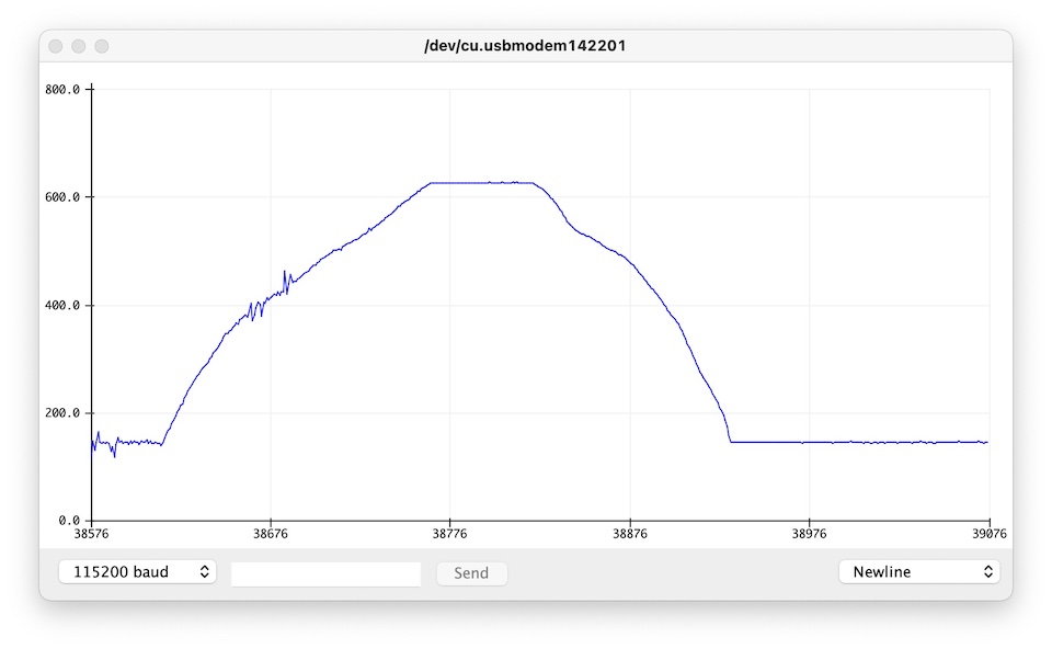
The result in the serial plotter is shown here:
Motor Driver
group assignment
For the group work we tried to measure the power consumption of a stepper motor. The stepper is able to operate at different voltages, so if the voltage oes up, the current should go down. And it more or less did, within some limits the power consumption was around 2,3 W. Ben made a nice detailed account of our session on his page.
The group work ended with a bit of fun. Benthe and I were playing around with the stepper motors and finally attached my phone on the top of the pulley of one of the motors.
3 phase AC motor
The outputs week was a good trigger to start investigating if I could drive a 3 phase AC motor. At de Waag we don’t have AC motors available – apart from the spindle of the ShopBot ;-P – so I did some research if other motors could serve that research goal. I investigated mainly Wikipedia, starting on the synchronous motor page.
My first idea was to (mis)use a stepper motor, so I could at least try to program two phase shifted waves and feed them to the two circuits of a stepper. As far as I could find, a stepper has basically two magnetic circuits and also permanent magnets that align the steps made. In the end it turned out that Henk had power combo with a brushless DC somewhere in his stack and that was perfect. Brushless DC motors are almost exactly the same as AC motors.
This type has 12 poles that are configured in 2 coils and 3 phases. Just what I need. It’s an outrunner with 14 magnetic poles, which is a bit different from a regular PMSM. Most likely this is done to reduce torque ripple, so I guess this won’t cause a problem. I want to drive it directly, so I desoldered the motor from the controller part. This was useless anyway, because there’s no documentation about it other than instructions how to program it when connected to you copter kit.
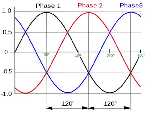
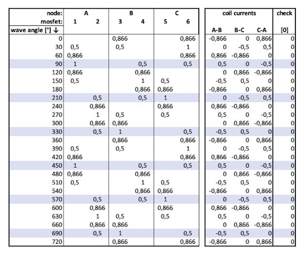
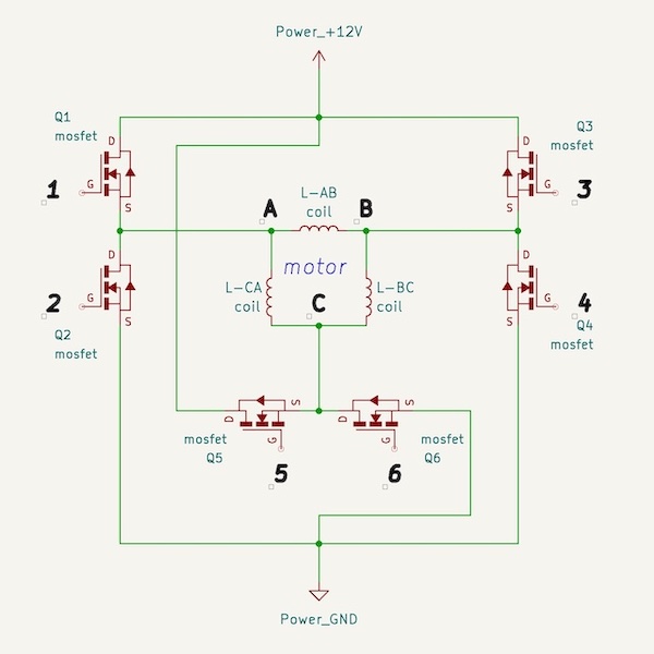
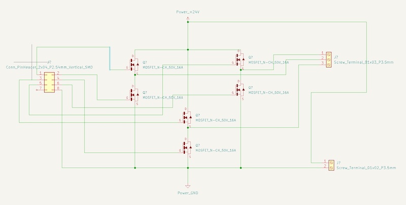
To be able to program the µC I need to understand better the way the currents behave. So I made a table representing the sine wave of the 3 phases and calculated the corresponding switch states of the mosfets and the resulting currents in the coils. In the last column I did a check, because the ∆ configuration is a closed system and the sum of currents should be zero.
| sine waves | current table | system schematic |
|---|---|---|
 |
 |
 |
When making the table I was triggered by something that could go wrong in programming. Excel functionality needs you to convert degrees into radians. The limited accuracy of excel led to an outcome that was not exactly zero. In the µC this could happen too and this could lead to switching on two mosfets on the same node, creating a short circuit. When programmng I have to make sure this is not possible.
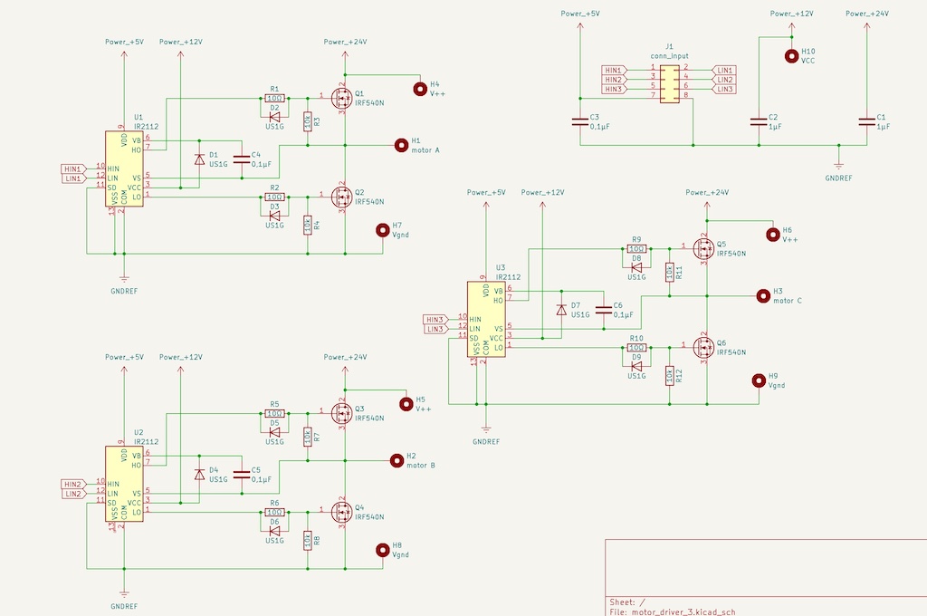
Motor Driver Board
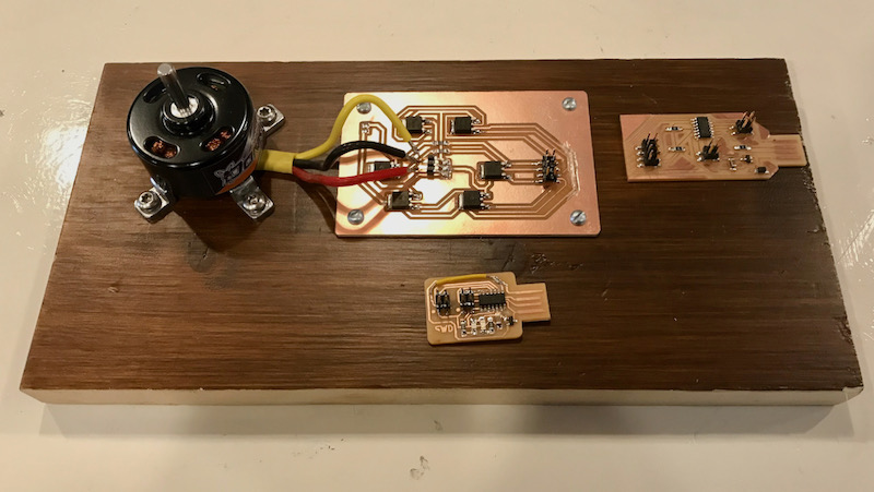
To be fexible and to separate the high power part from the low power I made a dedicated motor driver board. It has 6 mosfets, 2 for each connection of the motor. Below you can find the schematics.
For the complete set up with the control board I just used a some wood to screw it all together.
Programming
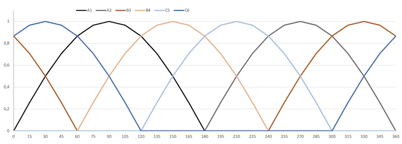
For the programming I converted the sine values into 8 bit values for each mosfet. The idea is to make a loop and use the analogWrite funtion in 24 steps with a value for each output pin.
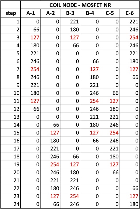
The picture on top is not the right representation of that table, it should be bar shaped, but it does show the phase shift. The bottom one shows the real input for two mosfets on the same coil node. My expectation is that the self induction of the coils will damp this signal and will probably make it more sine wave in effect.

The program uses tables to define the sine wave steps. Here’s the complete version:
// program for simulating 3 phase sine wave motor control

// definitions of output pins
// A, B and C are motor coil nodes
// _up is mosfet to Vcc; _dn is mosfet to gnd
#define A_up 4
#define A_dn 5
#define B_up 8
#define B_dn 9
#define C_up 14
#define C_dn 15
// hall sesnro pin
#define hall_pin 2

int hall_val = 0;
int hall_map = 0;

// definition of input pin when speed ctrl is active
// definition of initial delay
unsigned long step_length = 20;

// definition of arrays for sine values for all mosfets
int sineValsAup[24] = {  0,  66, 127, 180, 221, 246, 254, 246, 221, 180, 127,  66,   0,   0,   0,   0,   0,   0,   0,   0,   0,   0,   0,   0};
int sineValsAdn[24] = {  0,   0,   0,   0,   0,   0,   0,   0,   0,   0,   0,   0,   0,  66, 127, 180, 221, 246, 254, 246, 221, 180, 127,  66};
int sineValsBup[24] = {221, 180, 127,  66,   0,   0,   0,   0,   0,   0,   0,   0,   0,   0,   0,   0,   0,  66, 127, 180, 221, 246, 254, 246};
int sineValsBdn[24] = {  0,   0,   0,   0,   0,  66, 127, 180, 221, 246, 254, 246, 221, 180, 127,  66,   0,   0,   0,   0,   0,   0,   0,   0};
int sineValsCup[24] = {  0,   0,   0,   0,   0,   0,   0,   0,   0,  66, 127, 180, 221, 246, 254, 246, 221, 180, 127,  66,   0,   0,   0,   0};
int sineValsCdn[24] = {221, 246, 254, 246, 221, 180, 127,  66,   0,   0,   0,   0,   0,   0,   0,   0,   0,   0,   0,   0,   0,  66, 127, 180};

void setup() {
  // pinmodes output to mosfets
  pinMode(A_up, OUTPUT);
  pinMode(A_dn, OUTPUT);
  pinMode(B_up, OUTPUT);
  pinMode(B_dn, OUTPUT);
  pinMode(C_up, OUTPUT);
  pinMode(C_dn, OUTPUT);
  // pinmode input from control device
  // pinMode(hall_pin, INPUT);
  // step_length = map(hall_val, 128, 640, 1, 1023);
  Serial.begin(115200);
}

void loop() {
  // calculation of step_length when speed ctrl is active
  /* analogWrite(A_up, 0);
  analogWrite(A_dn, 0);
  analogWrite(B_up, 0);
  analogWrite(B_dn, 0);
  analogWrite(C_up, 0);
  analogWrite(C_dn, 0);
  Serial.println("____reset____");
  delay(1000); */
  // every increment takes the next value of the array
  for (int k = 0; k < 23 ; k++){
    Serial.print(sineValsAup[k]);
    Serial.print("; ");
    analogWrite(A_up, sineValsAup[k]);
    Serial.print(sineValsAdn[k]);
    Serial.print("; ");
    analogWrite(A_dn, sineValsAdn[k]);
    Serial.print(sineValsBup[k]);
    Serial.print("; ");
    analogWrite(B_up, sineValsBup[k]);
    Serial.print(sineValsBdn[k]);
    Serial.print("; ");
    analogWrite(B_dn, sineValsBdn[k]);
    Serial.print(sineValsCup[k]);
    Serial.print("; ");
    analogWrite(C_up, sineValsCup[k]);
    Serial.println(sineValsCdn[k]);
    analogWrite(C_dn, sineValsCdn[k]);
    // hall_val = analogRead(hall_pin);
    Serial.println(hall_val);
  //  step_length = 680 - hall_val;
    delay(step_length);
  }
}
Debugging
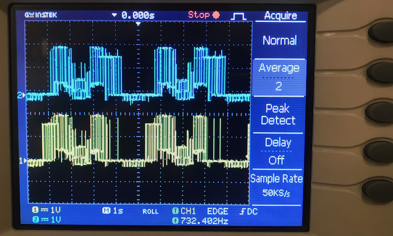
Unfortunately the motor doesn’t work. To check the signals I replaced the motor with 3 resistors of 1 kΩ. Below is a screenshot from the oscilloscope on two nodes.
During question time of the global review my suspicion was confirmed that I shouldn’t use N-channel mosfets on both side of the load. Peculiar thing is that in most datasheets of H-bridges the schematics do not show different types. Searching on the web for answers I discovered that if mosfets are used in a discrete set up, usually a gate driver is included to compensate the different voltage levels on high side mosfet and low side mosfet.
From a local vendor I oredered new mosfets, both P-channel and N-channel versions. On the original driver board I made some patches to be able to use these new mosfets; the are through hole instead of surface mount. But it still this doesn’t work. Unfortunately the knowledge within fabacademy about analogue electronics is not very deep. What I did assume already is to deep dive into gate driver technology. But reading dataasheets about that exceeds my understanding at the moment.
So where to look? finally during regional review, I got a tip from Stephane from Brussels. On youtube there’s a good channel from Foolish Engineer. Let’s spend a weekend looking tutorials. :-P
Improvements
Second Version
The result in that week was not a working motor driver. So I had to do a lot research more about that. First I looked into Niels suggestion to use P-channel mosfet on the high side. I ordered some extra mosfets because the standard ones in de Waag are not able to handle the large current I need. After some research I chose the IRF540 and the IRF9540 from Infineon. I didn’ make a new board, but just patched them onto the existing one and first checked only a half bridge before doing a total remake.
| patched board | set-up |
|---|---|
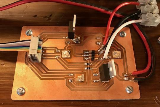 |
 |
Well, it didn’t work. Some more research suggested I should need a gate driver. Microcontroller outputs are not capable of feeding both the voltage levels and the current needed to feed the gate of large mosfets. To select the right gate driver and dimension the right capaciters and resistors requires more than shallow knowledge. So I watched a lot of tutorials about the way mosfets work and about the way gate drivers work. Gate drivers have several purposes. They make sure the right Voltage level is applied to the gate, becuase that’s depending on if it’s on the high side or on the low side. But they also prevent damage to the microcontroller and assure that high and low side are never turned on at the same time.
Stephane from Bussels suggested the foolish engineer channel on youtube. He does a good job in explaining how mosfets and gate drivers work. So I went to work on that. Some application design tips in pdf archives I found gave also a bit of a clue. As far as I was able to fathom what they were about.
I designed a special board in the end with the schematics as shown here after ordering the gate driver from infineon that is readily available. But again, this board didn’t work. I used a small solenoid to check if it worked, but even the low side that should switch easily with a load on top, didn’t work at all.
I think there are no flaws in the production, but the design: I actually have no clue what I’m doing and within the fablabs I haven’t been able to find someone who knows how to design such a thing. At this point I did some more searching and found some videos about AC motor drivers. So that’s my next step: watch a lot of videos, again. :-P
Third Version
New videos, new insights and new design. I’ve learned a lot about mosfets and gate drivers watching more videos. One key point for mosfets, is that their gates work as a capacitor. When you want to switch your drain to source current on, you basically charge the gate capacitor and you especially on the high side mosfet, you use a bootstrap capacitor to charge the mosfet capacitor, because you need a voltage level related to the drain side of the low side mosfet. Funny thing is that you can switch your mosfet by just charging it with your fingertips as you can see in the short video below.
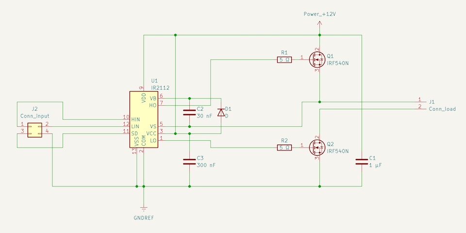
My new design is a combination of copying values used by others and calculations using some application notes and design tips I have found. The gate resistor reduces oscilations when switching on and the diode ensures a fast switching off. The bootstrap capacitor calculation is complicated and I’m not sure I got it right, but I can change it easily to a different value later. The gate driver logic is fed from the control board with 5 V and the Vcc that is used to feed the gate current is separated from the main power to be able to give them separate voltages. BTW: the power 24V is only chosen to separate it, but any voltage up to 100 V, which is the limit of the mosfet, should work.
My first idea was to make only one half bridge to try it out, but the point is that you need a full bridge to get it working, because the current will flow from the high side of the first half bridge to the low side of the second. And it’s also easier to combine them because otherwise the 3 noise reduction capacitors will get a parallel higher value.
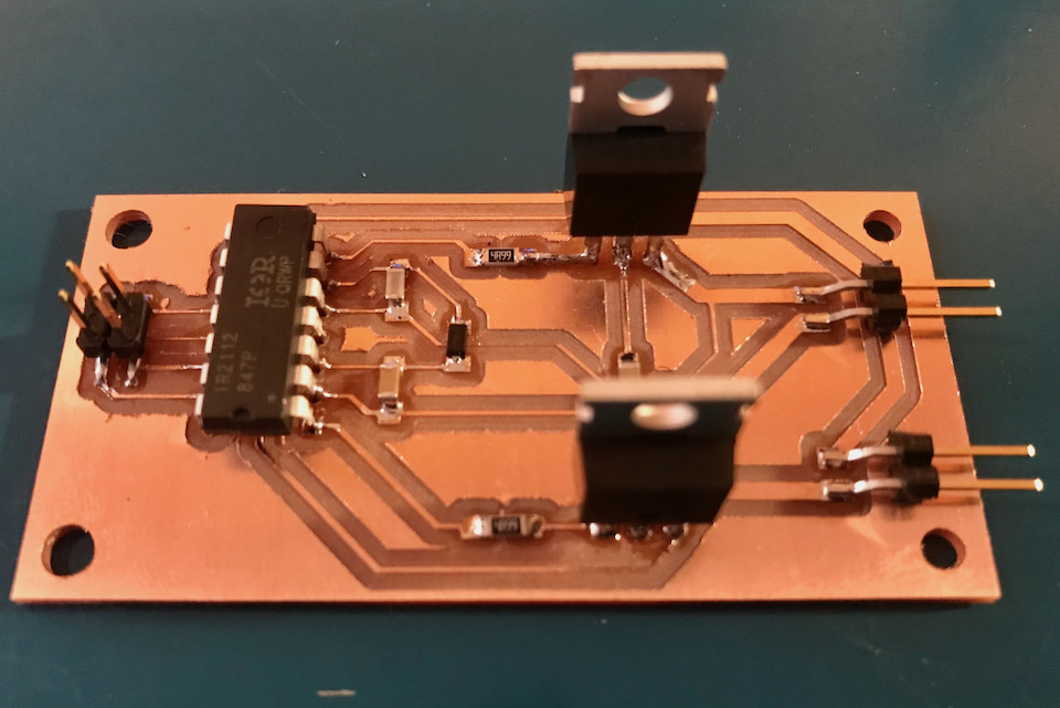
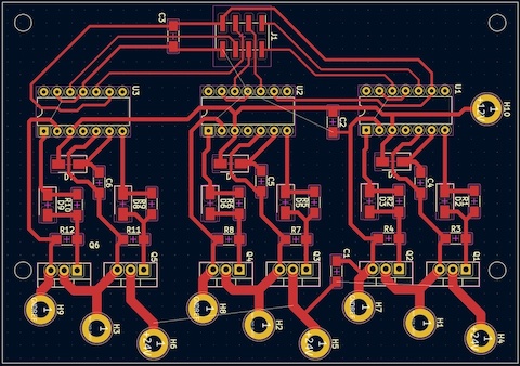
To allow the high current for the motor I made big pads for the power supply, the ground and the motor nodes. During soldering I filled the high current traces with extra solder. On the backside of the board I will make connections between the three sections using cables with terminals and screws. The use of through hole components allows me also to connect the ground of the different sections using patches on the back, so I don’t need 0 Ω resistors to create bridges.
The lay-out fits exactly on a standard board of 70 x 100 mm. A compact design is important also from functionality point of view, because the leads from gate driver, capacitors and mosftes should be as short as possible.
| board lay-out | finished board |
|---|---|
 |
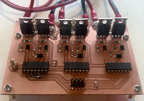 |
This looks really neat! But nope, still not working. I tested the board with my light bulb in triangle configuration, but the mosfets didn’t switch. At this point I decided to skip the VFD for my final project and use a simple DC-motor to drive the noise drum. The design for the DC motor driver is documented on the motor driver paragraph of my final project.
Finally, VFD Success
After finishing fabacademy I couldn’t let it go. Despite using a simple DC-driver I did some more research to try to get my VFD working. And, spoiler alert, I did get it working. So here’s an update of my work in the autumn of 2022. My strarting point was the end version of my motor driver board from the third version from the paragraph above.
Cuase of the Failure
After reading more about the way mosfets are used I started to realise that I should look into the bootstrap function. If you use mosfets on the high side and the low side - on the pus side and the ground side - you need to lift the gate voltage of the high side to make the high side mosfet switch. This is needed because the N-type mosfet only switches if the gate level is at least at the level of the power voltage.
This is the function of the bootstrap circuit. Between the source of the low side mosfet and the VB (bootstrap output) of the gate driver a capacitor is connected (see pictire below). This capacitor will be loaded when the low side is “on”. When the low side is switched “off” the load of the capacitor will raise the VB-level. The gate driver will transfer tis higher level to the high output HO to the gate of the high side mosfet and will make it switch.
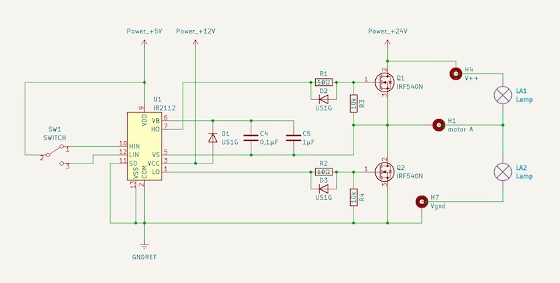
If there is too much time between switching the low side off and switching the high side on, the load of the capacitor will be gone and the voltage level of the gate of the high side mosfet will be too low to be able to switch.
To check this principle I made some changes to my original VFD-board and tried out different capacitors. In the pictures below I had a default bootstrap capacitor of 0,1 µF. During testing I added first 0,47 µF, then 4,7 µF and finally two capacitors of 4,7 µF. As you can see in the pictures, if the capacitor is too small at some point the “on” state of the high side is not maintained and it switches to “off”. Only the two capacitors of 4,7 µF are big enough to keep it on. The frequnecy is key here bu the way, because the capacitor defines the duraation, so if you are switching at higher frequencies you can use smaller capacitors.
| 0,1 µF | 0,1 + 0,47 µF |
|---|---|
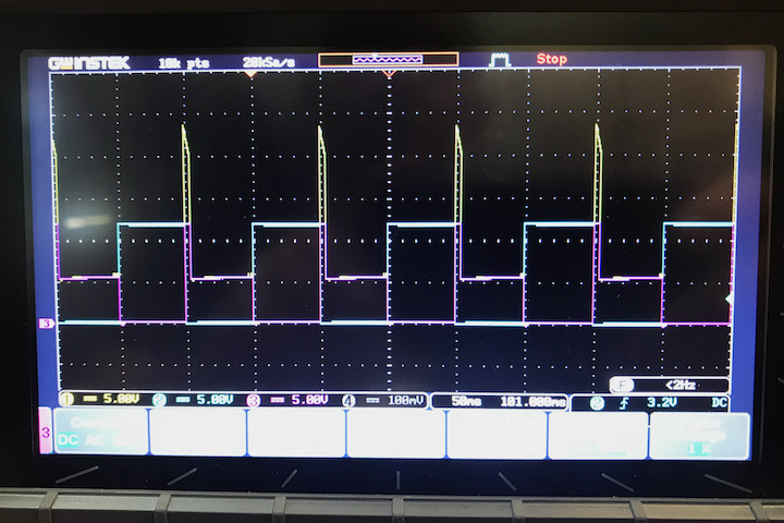 |
 |
| 0,1 + 4,7 µF | 0,1 + 2 x 4,7 µF |
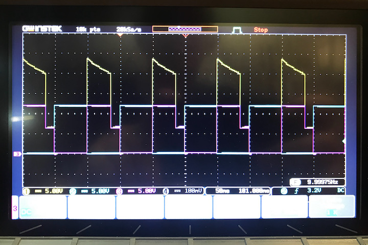 |
 |
Programming PWM
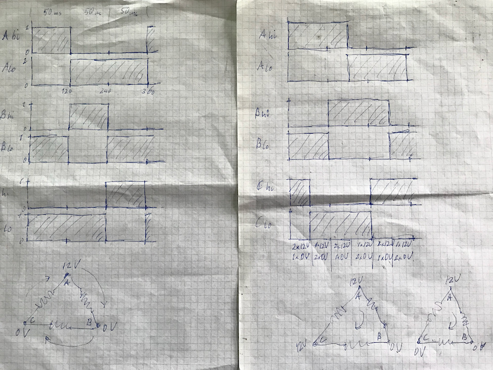
So far so good. Now I needed to adjust my programme to this new way of switching. First I tried to figure out on paper the “on” and “off” states of the nodes A, B and C of my motor. Having a motor in ∆ configuration, there are three points that can be switched to power or to ground. So which direction will the current flow through the motor coils in all 12 possible states. On the right side of the picture you can see how it works when you switch A, B and C 120° phase shifted.
This principle was translated in the code for my SAMD-board. To be able to control the speed I mapped the value of the Hall sensor of the throttle handle to the step length of the cycle. During testing I discovered that the motor will run smothly only between some limits, which is why the step length was constrained between 800 and 8000 µs. The reason for this is the type of motor I used. It’s originally a BLDC motor with 12 electric poles, but it has 14 permanent magnetic poles on the outrunner. This behaves only between certain limits as a synchronous AC-motor.
The footage below shows the test I did with light bulbs to simulate the motor. First there’s a detailed film of the bulbs only.
And here’s one that show also the signals on the oscilloscope.
As you can see this is a simple version with a square wave as derived from the sketch on paper. Afterwards I tried to simulate a sine wave using a makeshift PWM. As you can see on both the picture and the footage of the oscilloscope it does work nicely.

This makes the code I wrote in Arduino IDE a bit complicated, becuase I need to define 36 steps in total to describe this signal. And that’s even when limited to only three different pulse widths of 1, 2 and 4 times the step length.
// testprogram for switching 1 motor control mosfet half bridge

// definitions of output pins
// A, B and C are motor coil nodes
// _hi is mosfet to Vcc; _lo is mosfet to gnd
#define A_hi 4
#define A_lo 5
#define B_hi 8
#define B_lo 9
#define C_hi 14
#define C_lo 15

// definition of input pin when speed ctrl is active - hall sesnor pin
#define hall_pin 2
// hall_val is reading hall sensor; mapping is to adjust for the right delay bandwith
int hall_val = 0;

// definition of initial delay
unsigned int step_length = 1200;

void setup() {
  // pinmodes output to gate drivers A, B & C
  pinMode(A_lo, OUTPUT);
  pinMode(A_hi, OUTPUT);
  pinMode(B_lo, OUTPUT);
  pinMode(B_hi, OUTPUT);
  pinMode(C_lo, OUTPUT);
  pinMode(C_hi, OUTPUT);
  // initial state: all are HIGH on low side
  digitalWrite(A_lo,HIGH);
  digitalWrite(A_hi,LOW);
  digitalWrite(B_lo,HIGH);
  digitalWrite(B_hi,LOW);
  digitalWrite(C_lo,HIGH);
  digitalWrite(C_hi,LOW);
  // pinmode input from control device
  pinMode(hall_pin, INPUT);
  Serial.begin(115200);
}

void loop() {
  hall_val = analogRead(hall_pin);
  // Serial.print(hall_val);
  // Serial.print("; ");
  step_length = map(hall_val, 128, 640, 1200, 200);
  step_length = constrain(step_length, 200, 1200);
  // Serial.println(step_length);
  // step 1b
  delayMicroseconds(step_length);
  // step 2 t/m 5
  digitalWrite(A_lo,LOW);   // A naar HIGH
  digitalWrite(A_hi,HIGH);
  delayMicroseconds(4*step_length);
  // step 6
  digitalWrite(A_hi,LOW);   // A naar LOW
  digitalWrite(A_lo,HIGH);
  delayMicroseconds(step_length);
  //step 7 & 8
  digitalWrite(A_lo,LOW);   // A naar HIGH
  digitalWrite(A_hi,HIGH);
  delayMicroseconds(2*step_length);
  // step 9
  digitalWrite(A_hi,LOW);   // A naar LOW
  digitalWrite(A_lo,HIGH);
  digitalWrite(B_lo,LOW);   // B naar HIGH
  digitalWrite(B_hi,HIGH);
  delayMicroseconds(step_length);
  //step 10
  digitalWrite(A_lo,LOW);   // A naar HIGH
  digitalWrite(A_hi,HIGH);
  digitalWrite(B_hi,LOW);   // B naar LOW
  digitalWrite(B_lo,HIGH);
  delayMicroseconds(step_length);
  // step 11 & 12
  digitalWrite(A_hi,LOW);   // A naar LOW
  digitalWrite(A_lo,HIGH);
  digitalWrite(B_lo,LOW);   // B naar HIGH
  digitalWrite(B_hi,HIGH);
  delayMicroseconds(2*step_length);
  // step 13
  digitalWrite(B_hi,LOW);   // B naar LOW
  digitalWrite(B_lo,HIGH);
  delayMicroseconds(step_length);
  // step 14 t/m 17
  digitalWrite(B_lo,LOW);   // B naar HIGH
  digitalWrite(B_hi,HIGH);
  delayMicroseconds(4*step_length);
  // step 18
  digitalWrite(B_hi,LOW);   // B naar LOW
  digitalWrite(B_lo,HIGH);
  delayMicroseconds(step_length);
  // step 19 & 20
  digitalWrite(B_lo,LOW);   // B naar HIGH
  digitalWrite(B_hi,HIGH);
  delayMicroseconds(2*step_length);
  // step 21
  digitalWrite(B_hi,LOW);   // B naar LOW
  digitalWrite(B_lo,HIGH);
  digitalWrite(C_lo,LOW);   // C naar HIGH
  digitalWrite(C_hi,HIGH);
  delayMicroseconds(step_length);
  // step 22
  digitalWrite(B_lo,LOW);   // B naar HIGH
  digitalWrite(B_hi,HIGH);
  digitalWrite(C_hi,LOW);   // C naar LOW
  digitalWrite(C_lo,HIGH);
  delayMicroseconds(step_length);
  // step 23 & 24
  digitalWrite(B_hi,LOW);   // B naar LOW
  digitalWrite(B_lo,HIGH);
  digitalWrite(C_lo,LOW);   // C naar HIGH
  digitalWrite(C_hi,HIGH);
  delayMicroseconds(2*step_length);
  // step 25
  digitalWrite(C_hi,LOW);   // C naar LOW
  digitalWrite(C_lo,HIGH);
  delayMicroseconds(step_length);
  // step 26 t/m 29
  digitalWrite(C_lo,LOW);   // C naar HIGH
  digitalWrite(C_hi,HIGH);
  delayMicroseconds(4*step_length);
  // step 30
  digitalWrite(C_hi,LOW);   // C naar LOW
  digitalWrite(C_lo,HIGH);
  delayMicroseconds(step_length);
  // step 31 & 32
  digitalWrite(C_lo,LOW);   // C naar HIGH
  digitalWrite(C_hi,HIGH);
  delayMicroseconds(2*step_length);
  // step 33
  digitalWrite(C_hi,LOW);   // C naar LOW
  digitalWrite(C_lo,HIGH);
  digitalWrite(A_lo,LOW);   // A naar HIGH
  digitalWrite(A_hi,HIGH);
  delayMicroseconds(step_length);
  // step 34
  digitalWrite(C_lo,LOW);   // C naar HIGH
  digitalWrite(C_hi,HIGH);
  digitalWrite(A_hi,LOW);   // A naar LOW
  digitalWrite(A_lo,HIGH);
  delayMicroseconds(step_length);
  // step 35 & 36
  digitalWrite(C_hi,LOW);   // C naar LOW
  digitalWrite(C_lo,HIGH);
  digitalWrite(A_lo,LOW);   // A naar HIGH
  digitalWrite(A_hi,HIGH);
  delayMicroseconds(2*step_length);
  // step 1a
  digitalWrite(A_hi,LOW);   // A naar LOW
  digitalWrite(A_lo,HIGH);
}
All Running
For the final version I simplyfied the signal again, because the PWM simulation did not improve the way the motor was running at all. This again is probably because I’m misusing a BLDC-motor as an AC-motor. The simple version worked fine and I was able to reduce the code into only 12 steps and by combineng the into 4 blocks of steps.
// testprogram for switching 3 motor control mosfet half bridges
// set-up using square waves without overlap based on steps of 30°
// using throttle to adjust square wave width resulted in optimum with square_width is around 95 % of step_length
// motor runs more or less smoothly when 800 < step_length < 8000; outside motor will stall
// program is 92 % of available storage space

// definitions of output pins
// A, B and C are motor coil nodes
// _hi is mosfet to Vcc; _lo is mosfet to gnd
#define A_hi 4
#define A_lo 5
#define B_hi 8
#define B_lo 9
#define C_hi 14
#define C_lo 15

// definition of input pin when speed ctrl is active - hall sesnor pin
#define hall_pin 2
// hall_val is reading hall sensor; mapping is to adjust for the right delay bandwith
int hall_val = 0;

// definition of initial delay
unsigned int step_length = 4000;

void setup() {
  // pinmodes output to gate drivers A, B & C
  pinMode(A_lo, OUTPUT);
  pinMode(A_hi, OUTPUT);
  pinMode(B_lo, OUTPUT);
  pinMode(B_hi, OUTPUT);
  pinMode(C_lo, OUTPUT);
  pinMode(C_hi, OUTPUT);
  // initial state: all are HIGH on low side (connected to GND)
  digitalWrite(A_lo,HIGH);
  digitalWrite(A_hi,LOW);
  digitalWrite(B_lo,HIGH);
  digitalWrite(B_hi,LOW);
  digitalWrite(C_lo,HIGH);
  digitalWrite(C_hi,LOW);
  // pinmode input from control device
  pinMode(hall_pin, INPUT);
  Serial.begin(115200);
}

void loop() {
  hall_val = analogRead(hall_pin);
  Serial.print(hall_val);
  Serial.print("; ");
  step_length = map(hall_val, 140, 660, 4000, 800);
  step_length = constrain(step_length, 800, 4000);
  Serial.println(step_length);
  // step -1,5 = 10,5
  digitalWrite(A_lo,LOW);         // A naar HIGH
  digitalWrite(A_hi,HIGH);
  digitalWrite(B_hi,LOW);         // B naar LOW
  digitalWrite(B_lo,HIGH);
  delayMicroseconds(step_length);
  // step -0,5 = 11,5
  digitalWrite(C_lo,LOW);         // C naar HIGH
  digitalWrite(C_hi,HIGH);
  delayMicroseconds(step_length*5);
  // step 4,5
  digitalWrite(A_hi,LOW);         // A naar LOW
  digitalWrite(A_lo,HIGH);
  digitalWrite(B_lo,LOW);         // B naar HIGH
  digitalWrite(B_hi,HIGH);
  delayMicroseconds(step_length);
  // step 5,5
  digitalWrite(C_hi,LOW);         // C naar LOW
  digitalWrite(C_lo,HIGH);
  delayMicroseconds(step_length*5);
}
Ans as you can see below it results in a simple square wave shifted 120° in phase.
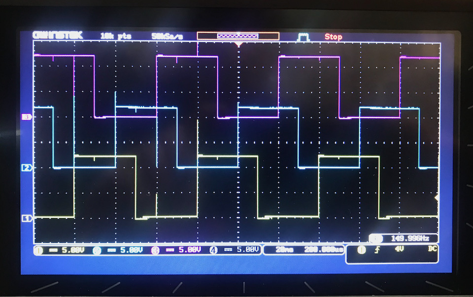
And finally my hero shot of a running three phase motor controlled by an electronic throttle handle. YEAEAHH!
Design Files
All KiCAD files can be downloaded from here: