10. Output Devices
Planning
Tasks - Must
- In group: Measure the power consumption of an output device
- Add an output device to a microcontroller board you’ve designed and program it to do something
Tasks - Nice to
- Do sensorless homing with a stepper motor
Execution
Group assignment
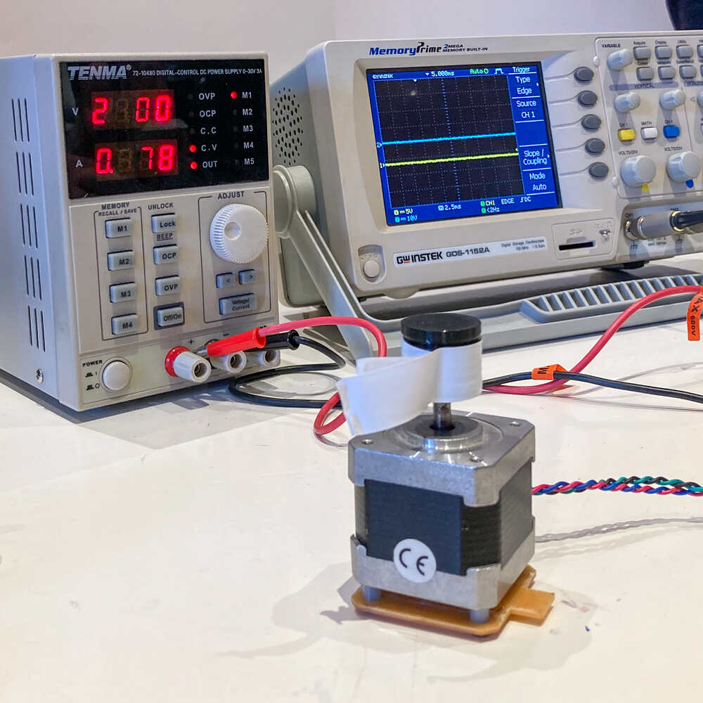
We’re going to measure the power consumption of stepper motors which are driven by an arduino CNC shield. We’re going to set the voltage, measure the current and calculate the power consumption.
First we did power the arduino CNC shield with 24V and we observed how much current was flowing (directly on the power supply) and calculated the power consumption accordingly.
There isn’t a big difference in the power consumption between a still and a moving motor.
We tried to power the motor driver at different voltages. 5V was the lowest voltage it was able to run at. At this voltage we measured.
Our current measurement wasn’t really stable. Taking that into consideration I’d say that the voltage doesn’t affect the power consumption too much.
When we were running the motor at higher voltages it felt like it was harder to stop it’s rotation by hand.
I’m not sure this can be generalized but based on our little experiment we can conclude that running a stepper motor at a higher voltage is better as it results in higher torque with a similar power consumption.
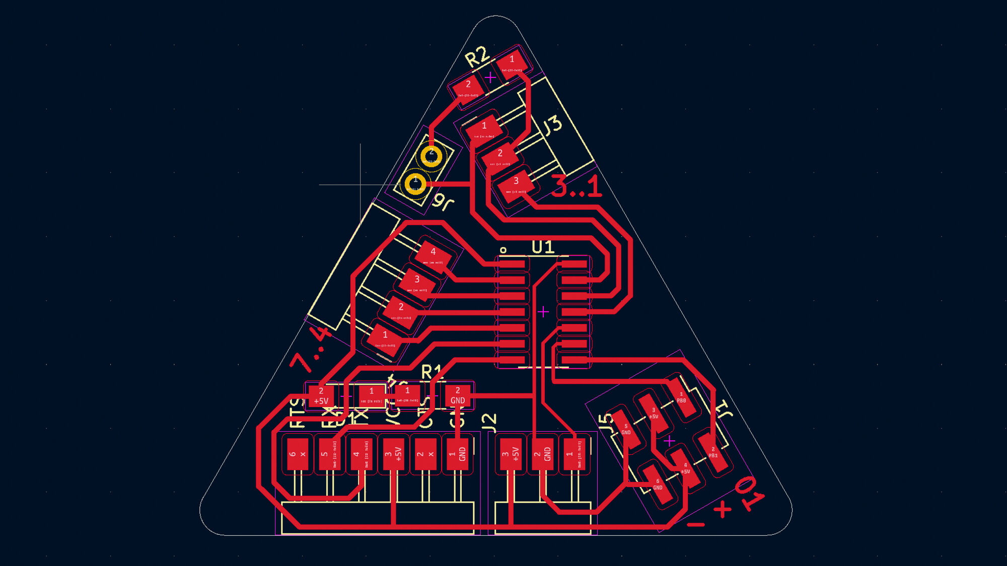
Generic breakout board 
Instead of designing a single board with a microcontroller and a stepper driver I decided to make two boards: A generic microcontroller breakout board and one for the stepper driver. By doing so I will be able to reuse the breakout board for other experiments.
My generic board uses the ATtiny1614 and provides
- FTDI connector for serial communication
- UPDI connector for programming
- Connector headers for other pins
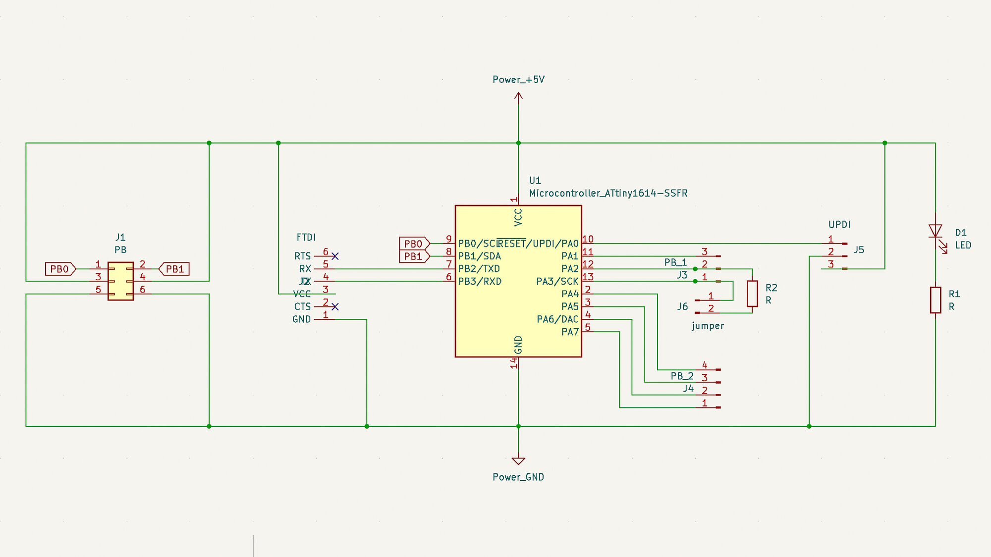
I positioned the FTDI and UPDI connectors so that they can be plugged into the USB-serial + UPDI board I designed in an earlier week.
Stepper driver board 
This week I will experiment with the TMC2209 stepper driver.
I’m excited about this driver because of its sensorless load measurement technology (based on back EMF measurement). This feedback makes it possible to detect stalls and do sensorless homing.
This driver comes in a QFN package (quad flat no-lead) which is really small and has no leads. As this would be really challenging and maybe even impossible to solder with our equipment I will use the SilentStepStick breakout board.
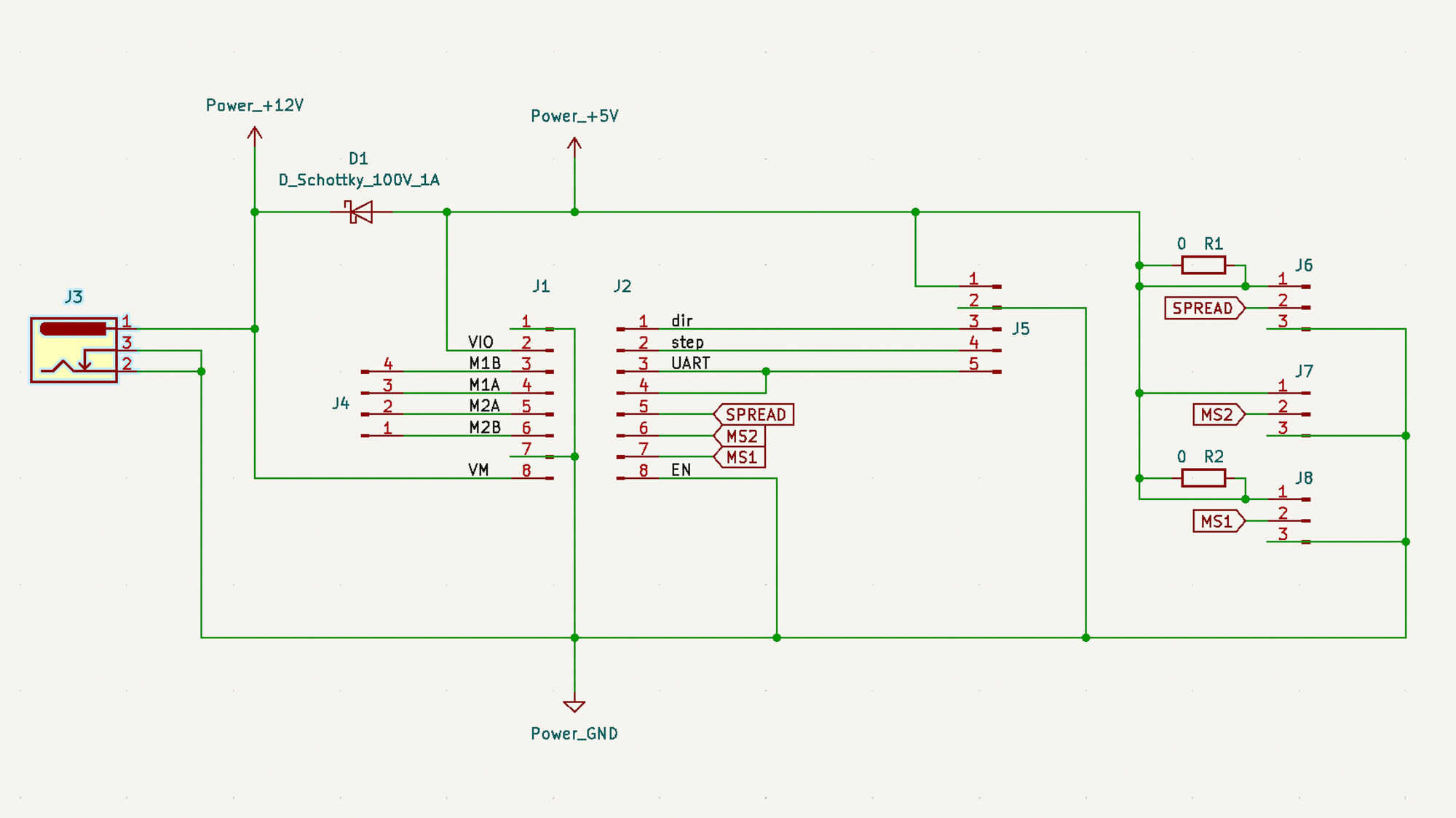
I designed a simple board to host the TMC2209 SilentStepStick and provide
- Jack connector for motor power
- Headers to connect motor
- Configuration jumpers
- Header connections to control the driver from the microcontroller
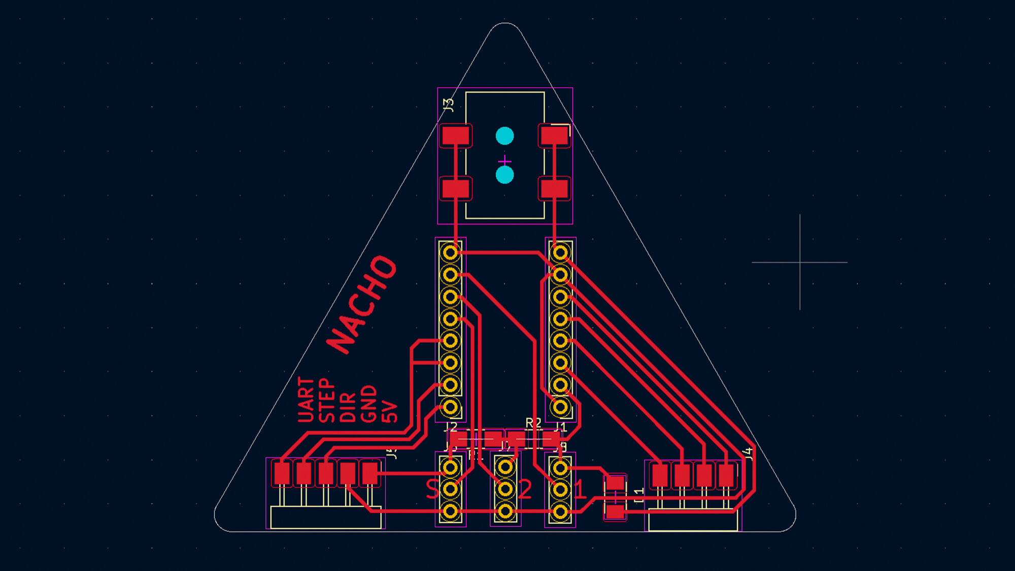
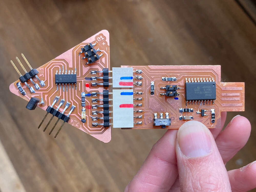
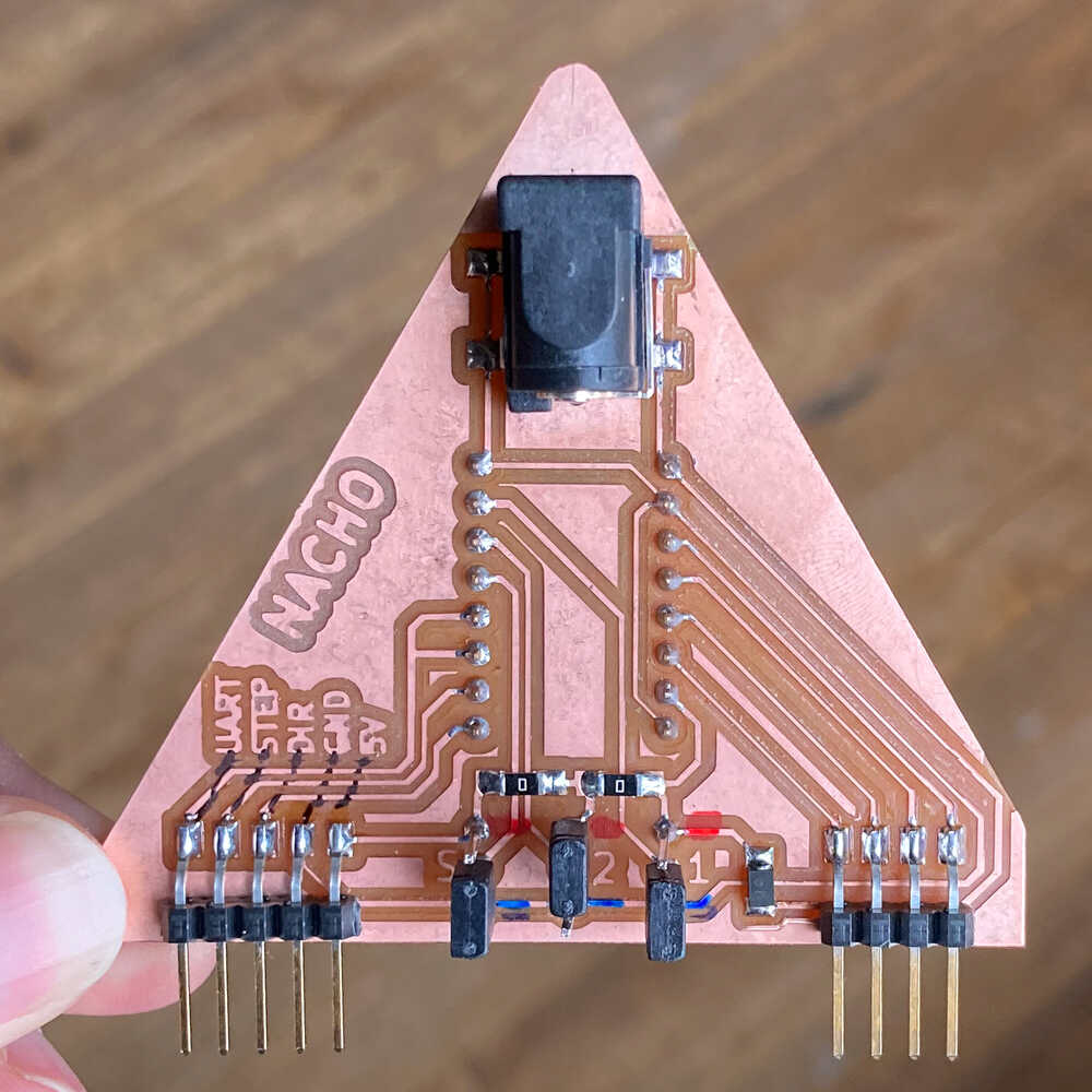
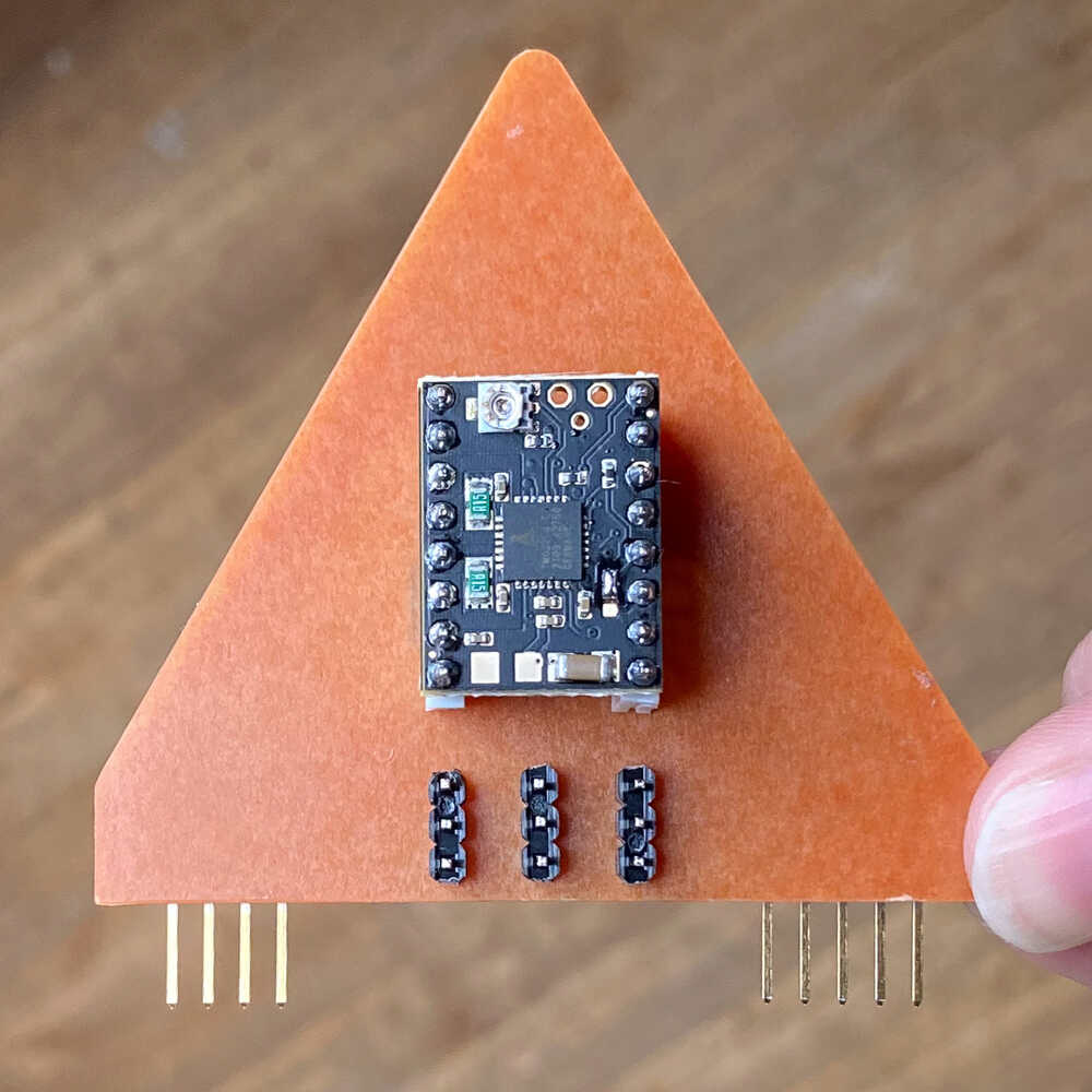
This is the completed board:
Driving the motor with STEP/DIR 
Once I had the boards completed I tested that everything works by writing a simple program that generates a pulse for the STEP input of the TMC driver and it worked :-)
UART connection to stepper driver 
To access advanced features like load measurement I have to connect to the TMC driver via its 1 wire UART interface.
The ATtiny1614 on my board has only one hardware serial interface. I want to keep using this interface for debugging and I therefore I tried to set up a software serial communication.
I configured SoftwareSerial to use the pins PA2 for RX and PA3 for TX and tested the setup with a slightly modified echo sketch.
RX
The microcontroller was able to send using SoftwareSerial but I couldn’t get RX to work. I thought PA2 should work as an RX pin without problem as it supports full asynchronous external interrupt detection. Not sure why this is not working
At this point I decided to replace the microcontroller on my board and use the ATtiny1624 instead. This microcontroller has the same pinout but has two hardware serial interfaces.
It was easy to remove the ATtinyt1614 by holding onto it with tweezers and heating the solder up with the heat gun until the microcontroller separated from the board.
Once I had soldered the ATtiny1624 in place I tested communication via it’s second hardware serial interface (Serial1) and it worked :-)
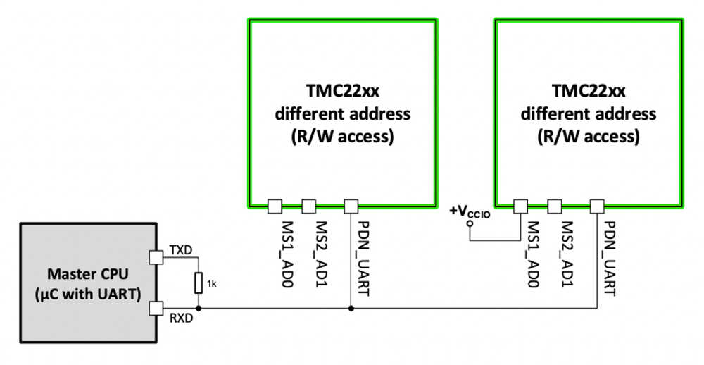
This image from the TMC2209 datasheet explains how to connect a microcontroller to the driver via 1 wire UART.
1 wire UART setup on microcontroller board
When I designed the microcontroller board I included a jumper that allows to connect RX and TX with a 1k resistor as needed for the 1 wire UART. Unfortunately the jumper doesn’t connect the Serial1 pins of the ATtiny1624 as I didn’t know that I was going to use this microcontroller when I designed the board.
I modified the board by cutting a trace with a utility knife and adding a flying wire to make things work for Serial1. The jumper now adds the resistor between PA1 (TX) and PA2 (RX).
To enable the UART interface on the TMC driver I bridget the jumper on the SilentStepStick board with solder as described in the documentation.
I configured the driver address to be 0b00 with the MS1 and MS2 jumpers of my board and I’m using this address in my sketch.
At this point I was ready to connect everything and try a simple program that changes the motors rotation direction every 5000 steps using the UART interface.
For the UART communication with the driver I use the TMCStepper library.
Read motor load from driver 
Now that I had the UART connection working I was ready to use it to do some interesting stuff.
I wrote a program that reads the StallGuard load value via the UART interface.
I forward the load reading to the other serial interface which is connected to my computer where I use arduino IDE serial plotter to visualize the value.
Note
A higher StallGuard reading indicates a less mechanical load
In the video you can see how the load measurement varies when I apply pressure to the motors shaft.
Retrospective
Designing and making boards is fun but it takes time. This week I made a generic breakout board and I hope that it will be useful in future weeks to get experimenting quicker.
Once the boards were complete it didn’t take long to get a basic setup working where the microcontroller was controlling the stepper motor. Next I tried to connect to the stepper driver via the serial interface and that turned out to be trickier than expected and it took quite a while until I got it working.
Once I had the serial communication working I was super happy that I managed to read the motor load from the driver.
My goal was to use the motor load reading to do sensorless homing. I didn’t get to that yet but it feels like I’m close :-)