8. Embedded programming
Planning
Tasks - Must
- In group: Compare the performance and development workflows of different architectures
- Take a look at the datasheet of your microcontroller
- Use your programmer to program your board to do something
Tasks - Nice to
- Use interrupts in one of my programs
- Debug code running on microcontroller
- Use timers in one of my programs
- Generate a PWM signal and visualize it on an oscilloscope
- Try switch debouncing with capacitor
Execution
Group assignment
We compared the workflows when working with arduino boards, ATtiny boards and SAMD boards. We programmed different arduino boards and an ATtiny board using the steps described below. We didn’t have the chance to program a board with a SAMD microcontroller.
This is an overview of the programmers and adapter/bridge boards that can be used in the workflows below.
Arduino
Arduino boards come with a preprogrammed bootloader. They’re ready to go: Just connect them via USB and they’re ready for programming and serial communication.AVR / ATtiny
Programming
We’re not going to use a bootloader for ATtiny boards as programming them via UPDI is simple enough.To make it possible to program the boards from the arduino IDE I did install megaTinyCore with the following steps:
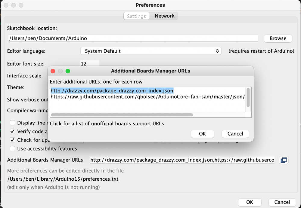
- Under
Arduino > Preferences > Additional board manager URLsI addedhttp://drazzy.com/package_drazzy.com_index.json - Under
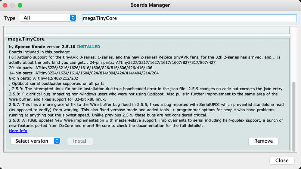
Tools > Board > Board manager...I installedmegaTinyCore
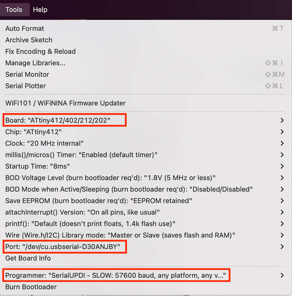
Once the board manager was installed I was able to select the following options under Tools to program my ATtiny412 board:
Serial communication
ARM / SAMD
Bootloader
To make it possible to program SAMD boards directly from the arduino IDE I installed ArduinoCore-fab-sam with the following steps: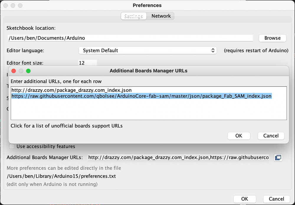
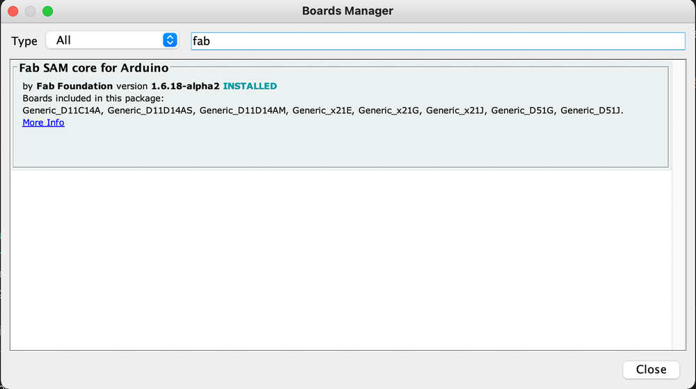
- Under
Arduino > Preferences > Additional board manager URLsI addedhttps://raw.githubusercontent.com/qbolsee/ArduinoCore-fab-sam/master/json/package_Fab_SAM_index.json - Under
Tools > Board > Board manager...I installedFab SAM core for Arduino
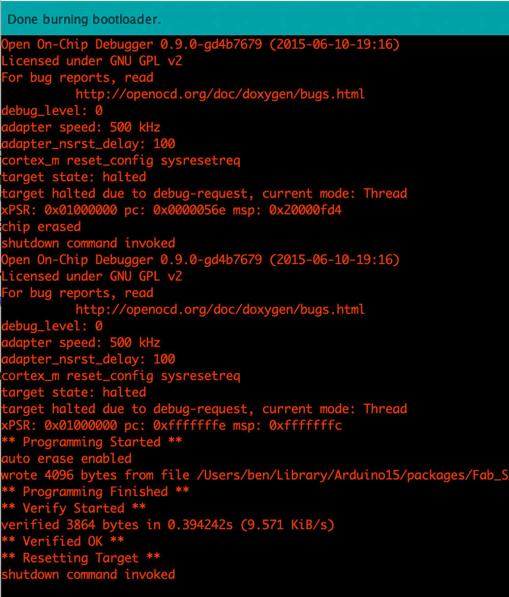
Once the board manager was installed I was ready to burn the bootloader.
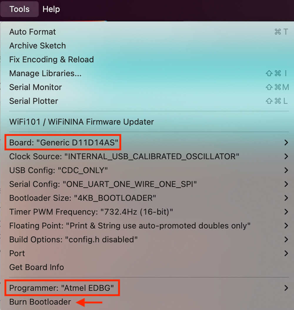
In the Tools menu I did:
- select the
Board(in my caseD11D14AS) - select
Programmerto beAmtel EDBG - Click
Burn Bootloader
edbg
At first I tried to burn the bootloader using edbg but I couldn’t get it to work. These are the steps I tried (just for reference):
brew install hidapi
git clone https://github.com/ataradov/edbg
make all

./edbg/edbg -bpv -e -t samd11 -f sam_ba_SAMD11D14AS.bin
Programming & Serial communication
Once the bootloader is on the SAMD microcontroller no additional boards are needed anymore: Just connect it via USB to load programs and for serial communication.As an example this is a sketch to make the SAMD behave as a USB to serial bridge. The readme explains how to upload the sketch to the board.
Microcontroller datasheet
On my hello world board there is an ATtiny412. There’s a lot of information in the datasheet. These are some sections that are interesting to me:
Make the board do something 
In the electronics design week I made a board containing ATtiny412, LED, switch and a phototransistor.
I will write a small program that uses all components: The LED will blink at different speeds depending on the light detected by the phototransistor. The switch allows to choose between 3 modes. Each mode adds a different multiplier to the LED blink delay. The mode selection is handy to tune the blink delay range for different lighting conditions.
At first I did check if the switch is pressed in the main loop. This is not ideal specially when the LED is blinking slowly as I check if the button is pressed only once per blink cycle. That means that it might be necessary to press the button for 2 seconds if that’s the time it takes for one blink. To avoid this limitation I adjusted the program to use an interrupt to detect the switch press. By doing so the mode can be adjusted straight away when the switch is pressed without waiting for any LED blinks.
Serial.println inside interrupt routine
I tried to write a message to serial inside the interrupt routine but it didn’t work and it blocked the entire program. It turns out that it’s failing because serial communication uses interrupts but interrupts are disabled while executing an interrupt routine. There is a more detailed explanation here.
In this video I show how switching mode makes the LED blink slower and slower. Once I’m in mode 3 I put my finger on the phototransistor to shade it and that makes the LED blink faster.
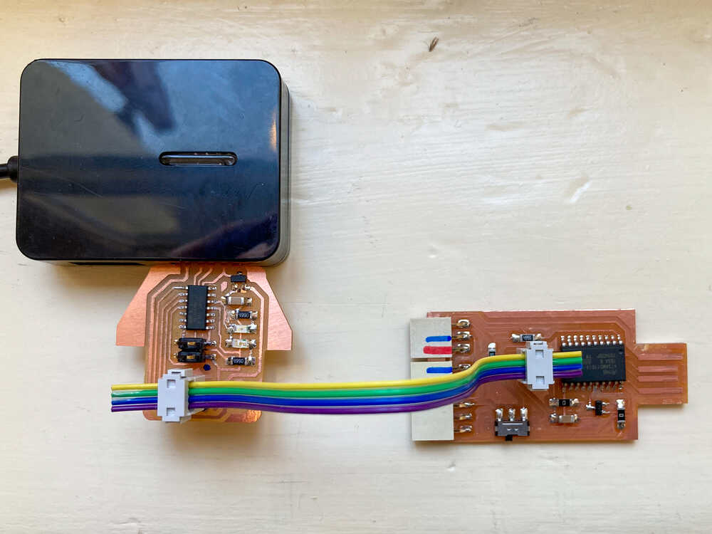
RX/TX connection
When writing the program I printed to serial for debugging purposes. At first it did not work: I designed my board in a way that the boards RX is connected to the Serial adapters RX. This is wrong as RX should be connected to TX. As a quick fix I made a hook up wire that just inverts TX and RX (green and orange wire).
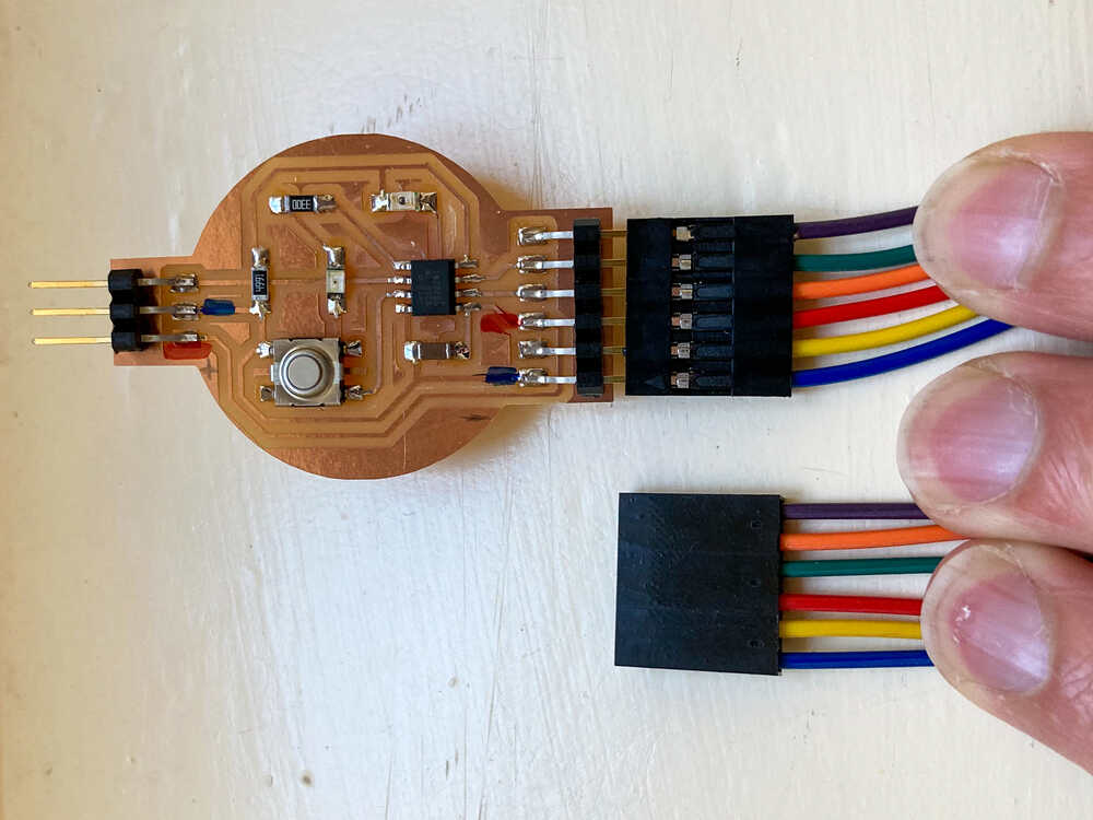
connection header direction
The UPDI and serial headers need to have their pins in the right order to match the ones in the USB serial and UPDI adapter boards. I designed my board in a way that the connector pins connect correctly when my board is upside down. This works but it would be handier fot the boards to connect correctly when they’re all facing up. To make sure I connect my boards correctly I marked the VCC and GND pins on all connectors.
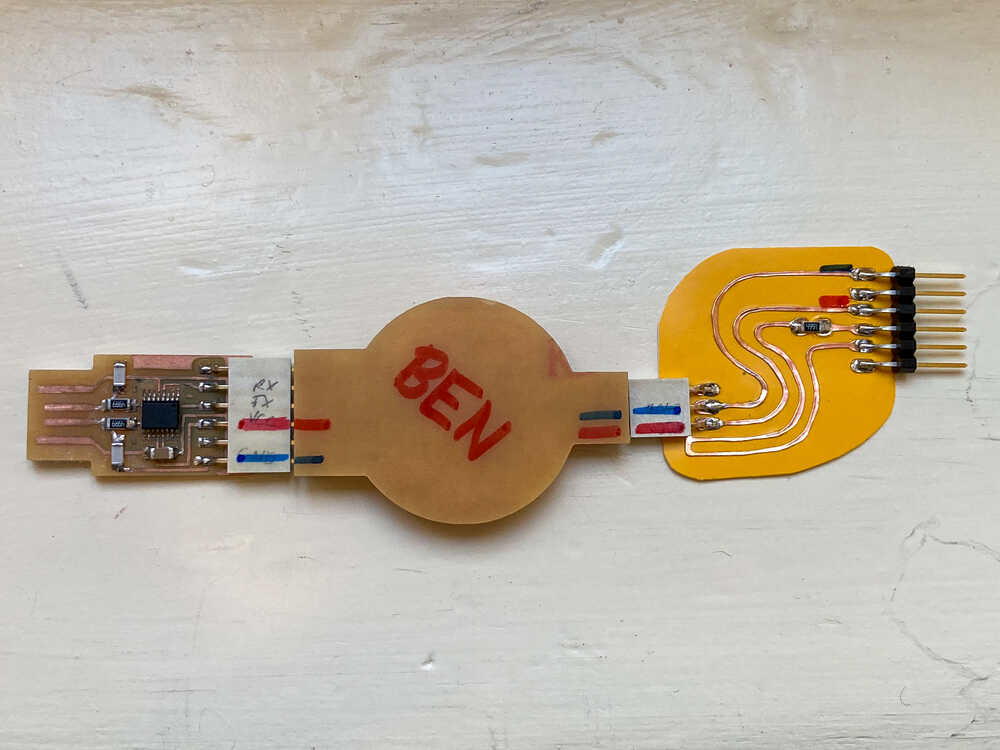
USB to serial & UPDI in one 
Design and production
While writing the program for my hello world board I found myself continuously plugging and unplugging the UPDI adapter to switch between programming and serial communication for debugging. It would be handy to have a board which can act as both USB to serial and UPDI programmer so I started to design one.
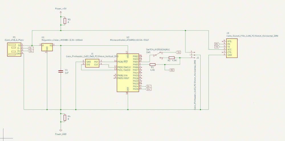
I took the schematic of the USB serial adapter board using the D11C as a starting point for my design.
I just had to add a UPDI connector, a resistor and a switch to select between programming and serial communication.
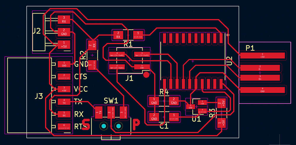
And this is the complete board:

Bigger microcontroller than necessary
When I finished milling the board I realized that I used the D11D instead of using the D11C. As I already had the board I decided to still go ahead. Even if this microcontroller is overkill there is no reason why I shouldn’t be able to get the board to work with it.
Programming header orientation
The programming header on my board has a different orientation than the ones on the SWD programmer. The header still works if connected properly but it would be clearer to keep the orientation of the programming header the same on all boards.
Programming
When I was searching for the sketch to make my SAMD board behave as a USB to serial bridge I found out that Quentin did already design a board which is really similar to mine (USB to serial + UPDI).
I successfully uploaded this sketch to my board.
Testing
When I tried to use my new board as a USB to serial bridge it did not work.
The sketch is using Serial2 and it turns out that Serial2 is mapped to different pins for D11C and D11D.
I could just modify my board and connect RX/TX to the pins 15/14 instead of 5/4 but I want to figure out if I could change the code to make it work.
I wasn’t sure how to tell the microcontroller and the arduino Serial library to use non-standard RX/TX pins so I reached out to Quentin to ask for a hint.
He explained that I could use pins 5/4 for serial by setting them to SERCOM-ALT in the Peripheral Multiplexing register. He did as well point me to this code containing an example of setting this register.
I copied the setup_peripheral method from the example and this is how I eded up using it:
#define PIN_TX 4
#define PIN_RX 5

void setup_peripheral(uint8_t pinNum, EPioPeripheral peripheral) {
    uint8_t pinCfg = (PORT->Group[PORTA].PINCFG[pinNum].reg & PORT_PINCFG_PULLEN);
    if ( pinNum & 1 ) { // odd pin
        uint32_t temp = (PORT->Group[PORTA].PMUX[pinNum >> 1].reg) & PORT_PMUX_PMUXE( 0xF ) ;
        PORT->Group[PORTA].PMUX[pinNum >> 1].reg = temp|PORT_PMUX_PMUXO( peripheral ) ;
    } else { // even pin
        uint32_t temp = (PORT->Group[PORTA].PMUX[pinNum >> 1].reg) & PORT_PMUX_PMUXO( 0xF ) ;
        PORT->Group[PORTA].PMUX[pinNum >> 1].reg = temp|PORT_PMUX_PMUXE( peripheral ) ;
    }
    pinCfg |= PORT_PINCFG_PMUXEN; // Enable peripheral mux
    PORT->Group[PORTA].PINCFG[pinNum].reg = (uint8_t)pinCfg;
}

void setup() {
  setup_peripheral(PIN_TX, PER_SERCOM_ALT);
  setup_peripheral(PIN_RX, PER_SERCOM_ALT);
}
At this point I told the microcontroller to use the non-standard pins but I still had to redefine the pins that the arduino serial library uses.
I tried the following code to redefine the serial pins but it did not work.
#undef PIN_SERIAL2_TX
#define PIN_SERIAL2_TX PIN_TX

#undef PIN_SERIAL2_RX
#define PIN_SERIAL2_RX PIN_RX
At that point I modified my local copy of ArduinoCore-fab-sam D11D pin definition which I found at ~/Library/Arduino15/packages/Fab_SAM_Arduino/hardware/samd/1.6.18-alpha2/var
iants/Generic_D11D14AS/variant.h (OSX) and that worked :-)
Afterwards I changed it back to the original values to avoid nasty surprises in the future.
Combine flexible and FR1 board 
In the past weeks I made some flexible circuits. The connectors are week points in these circuits as it’s easy to rip the traces off the circuit when plugging/unplugging. This week I’ll make a circuit which consists of flexible and non-flexible parts.
I will make a new UPDI adapter in the hope that I will end up with a stronger circuit than my current fully-flexible one.
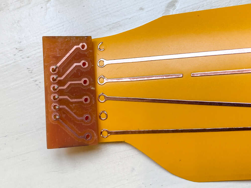 I started by milling little FR1 circuits for the pin header connectors. On one side of these small boards I will solder through-hole pin headers and on the other side I will attach them to the flexible circuit.
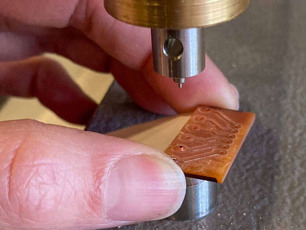 To attach the FR1 boards to the flexible circuit I used the rivets that would normally be used as vias in 2-layer boards.
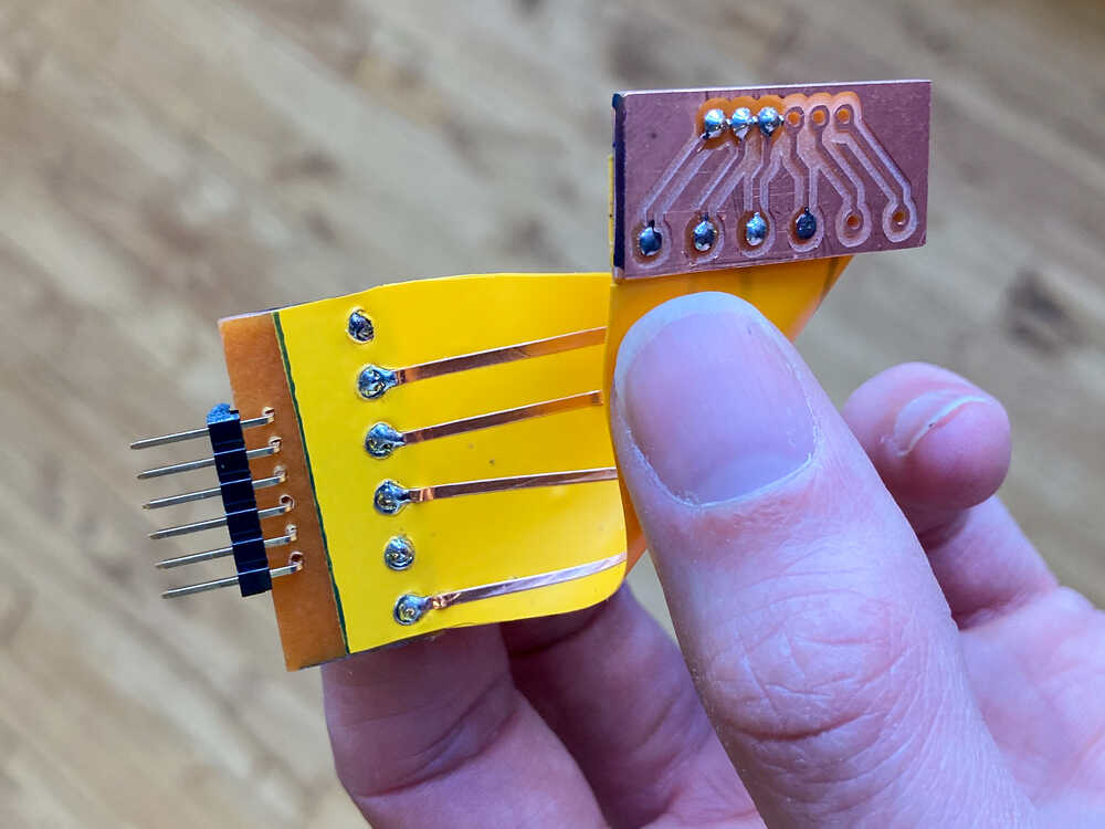 Once everything was riveted together I added solder to both sides of the rivets to make the joints stronger.
With this new approach the weak point is the joint between the flexible and non-flexible parts. I still think this board will perform better than the fully-flexible version because there is less stress on the joints between parts than on the connectors. With this new board it’s easy to hold onto the little FR1 boards while plugging/unplugging.
Retrospective
I’m really happy that I managed to put programs on both ATtiny and SAMD boards. By knowing how to do that and having everything setup on my machine, from now on I will be able to just program boards without worrying about learning how to do it and setting up things.
It has been frustrating while I was trying to burn the bootloader on a SAMD board with edbg and it just didn’t work but fortunately Henk showed me how to do it directly form arduino IDE and that works perfectly.
I’m convinced that having a USB - serial board which includes UPDI makes the programming/debugging cycle faster as I can switch between serial and programming mode quickly by just flipping a switch. Unfortunately I didn’t get my new board to fully work yet but I’ll continue trying.