13. Networking and communication
Planning
Tasks - Must
- Group: Send a message between two projects
- Design, build, and connect wired or wireless node(s) with network or bus addresses
Tasks - Nice to
- Make a full sized prototype of my final project
- Make a dual serial board
Execution
Group assignment
At the end of the local lesson Erwin showed us an example where 2 arduino boards were communicating over I2C. By regulating the potentiometer attached to Arduino 1 it was possible to control the brightness of the LED connected to Arduino 2.
Inspired by this example Bente and me made our own I2C communication setup.
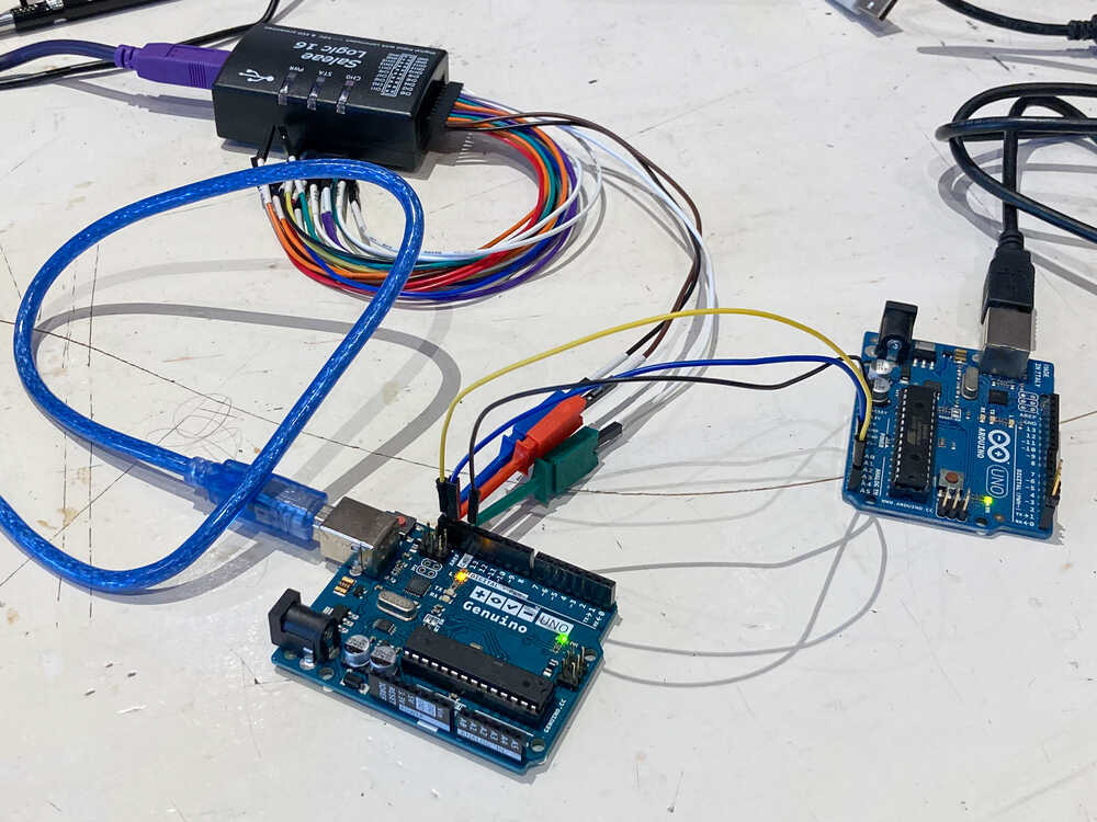
I wrote a program to send data over I2C and Bente implemented the receiving end.
At first no data was received. After debugging the communication with a logic analyzer and making a couple of corrections in the code we got it to work :-)
We found these examples really useful to get started with I2C sending and receiving.
Display ambient light reading 
Last week I experimented with an I2C light sensor. I will now make a setup with multiple I2C devices on the same communication lines:
- BH1750 light sensor
- OLED display to show the reading of the light sensor
I connected the components this way:

First I was wondering if it was necessary to add 4.7K pull-up resistors on the SCL and SDA lines but then I realized that it was not needed as they’re already included on the light sensor board.
Display address
At first the display was not working. After trying out multiple things I did run an I2C scanner sketch to find out the addresses of the I2C devices. It turns out that the address of my display is 0x3C and not 0x78 as written on the board. Once I used the address that was detected by the scanner things worked as expected.
In the video you can see how the displayed value changes when I put my finger on the light sensor.
Big libraries
At first I wanted to make this sensor + screen setup with a BNO055 absolute orientation sensor. It turns out that the resulting sketch (sensor libraries + screen libraries + my code) is too big to fit on my ATtiny1624. The sketch is ~18 KB and the microcontroller has 16 KB of flash memory.
To make this work I could use a microcontroller with more flash memory or see if I can avoid using one or more of the libraries.
Heliostat mirror position
For my final project I’m going to build a heliostat. I’m going to control the mirror position in order to continuously reflect the sun to the same spot even when the sun moves.
How do I know the current position of the mirror? I can think of two approaches:
1. Home steppers and keep track of position
For this approach to work I would have to do the following:
- Position the base of the heliostat in a predetermined way. e.g. the base perfectly level and the front pointing NORTH.
- Home the stepper motors when the device is turned on
- Keep track of the mirror orientation based on the steps performed by the motors
2. Use a sensor to measure the mirrors orientation
Measure the mirror position using an absolute orientation sensor like the BNO055.
If I use this approach it would be much easier to move the heliostat around. I made a couple of experiments to check if the BNO055 is accurate enough for my application.
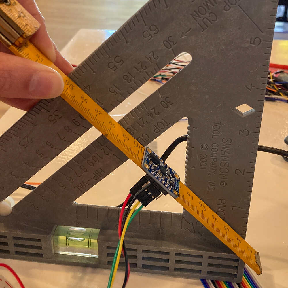
To check if the BNO055 is accurate enough for my application I did:
- Load a sketch that outputs the orientation of the sensor via serial (from this guide)
- Positioned the sensor at predetermined angles and checked the serial output
Based on a couple of tries the sensor output seems to be accurate to about +/- 2 degrees.

For a target at a distance of 20m, a deviation of 2 degrees results in the reflection being 0.7m off target.
I’d say this deviation is acceptable only for targets up to a distance of 10m or so.
As an alternative it could be used for rough positioning and then use a second sensor for fine positioning. I just found this project where they used separate rough/fine positioning sensors.
Half a bike heliostat
I want to build a full-sized heliostat prototype to be able to experiment with multiple aspects of my final project.
I was sitting in a cafe and thinking about possible ways of constructing the heliostat. I was wondering what kind of bearings to use and how to integrate them into the frame when a bike parked on the sidewalk attracted my attention… let me see how it’s done in a bike… the front part of a bike has two axes of movement like a heliostat. And why only take inspiration from a bike? I could use the front part of a bike as the structure for my project.
I went to the local bike shop and asked if they had an old bike that they were throwing away… and they did :-)
I started by removing everything I did not need from the bike and fixing it to my workbench to have it in a good position to work on.
Vertical movement 
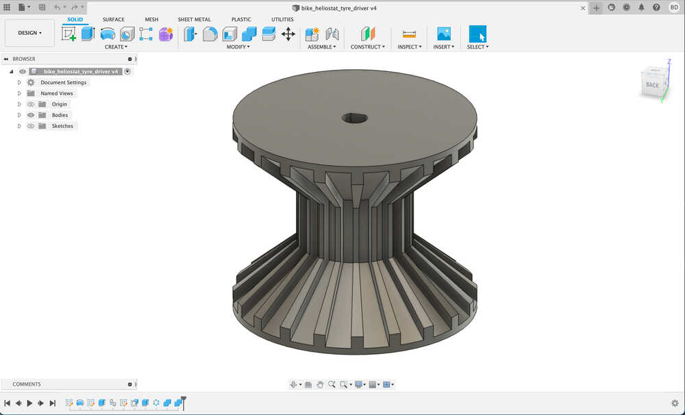
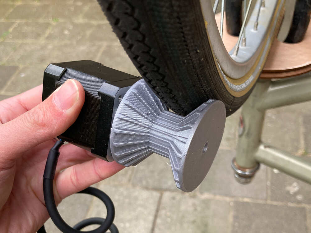
I will attach the mirrors to the bike wheel. To tilt the mirrors vertically I’ll have to turn the wheel. I’ll use a stepper motor to drive the wheel directly using a 3D printed wheel driving attachment.
Horizontal movement 
To move the mirrors horizontally I’ll turn around the bike’s fork. To do that I laser cut multiple parts that form a big pulley that is attached to the fork. The pulley is mounted to the fork with a 3D printed attachment.
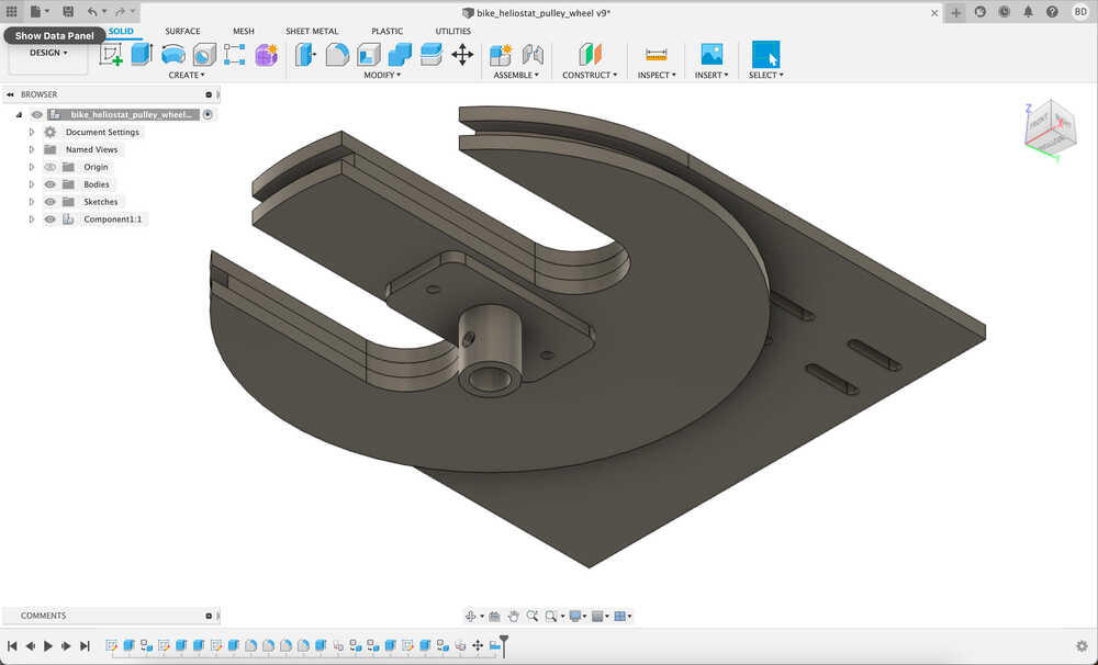
I’m going to use a GT2 timing belt to drive the pulley above from a stepper motor. The stepper motor is mounted to the bike frame with the following bracket:
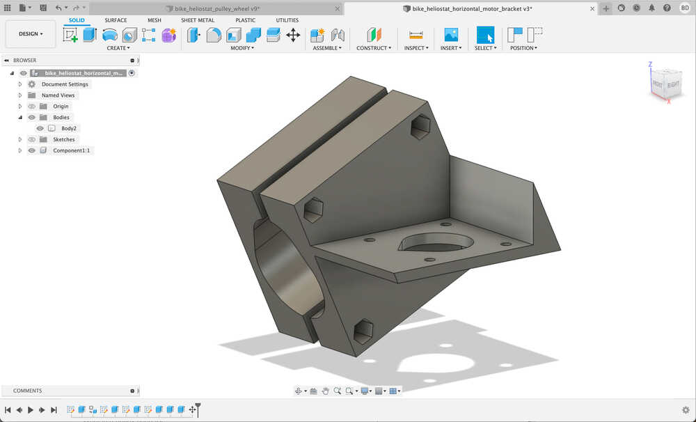
This is how it looks assembled:
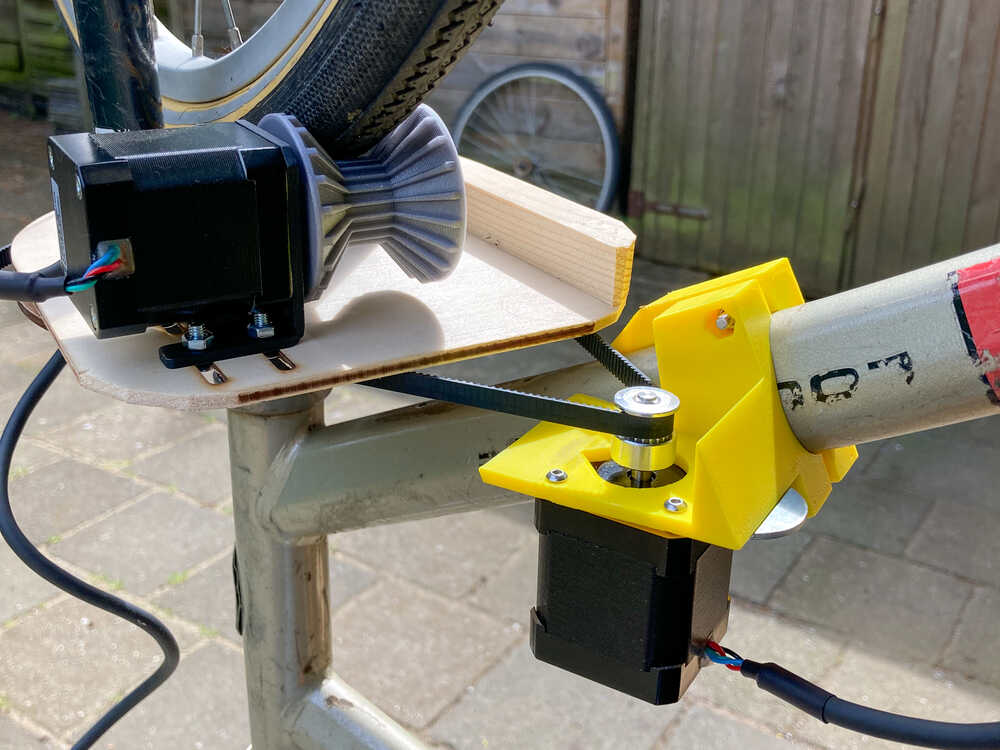
The motor for the vertical movement mounts directly on top of the horizontal movement pulley.
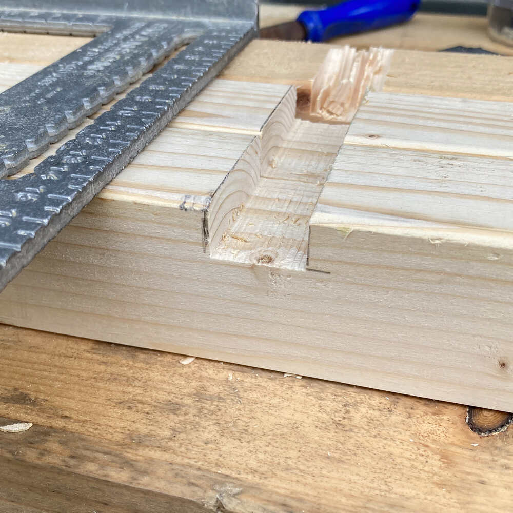
Bracket obstructing belt
I did not take into account the angle of the belt when designing the bracket to mount the motor to the bike frame. As a result the bracket was in the way of the belt. I made it work by cutting off a corner off the bracket with the hand saw.
Pulley top plate not sturdy enough
The wood I laser cut to make the pulley which is attached to the fork is quite flexible. Especially the top plate moves quite a bit when applying force to it. I’ll have to find a better way to mount the motor that interacts with the bike wheel. As a quick fix I attached a small slat to the top plate to make it more rigid.
Mirror mount
I’ve built a wooden frame that attaches to the bike wheel. The frame has a slot for the mirror to slide in and a cutout for the wheel.
Test run
Once I had everything assembled I programmed an arduino to make some test moves by controlling the steppers with a CNC shield:
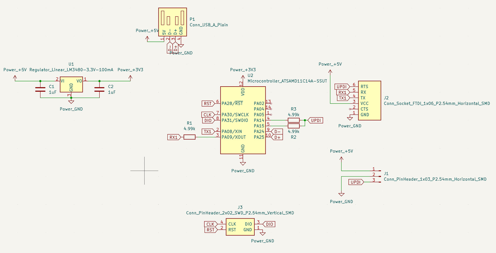
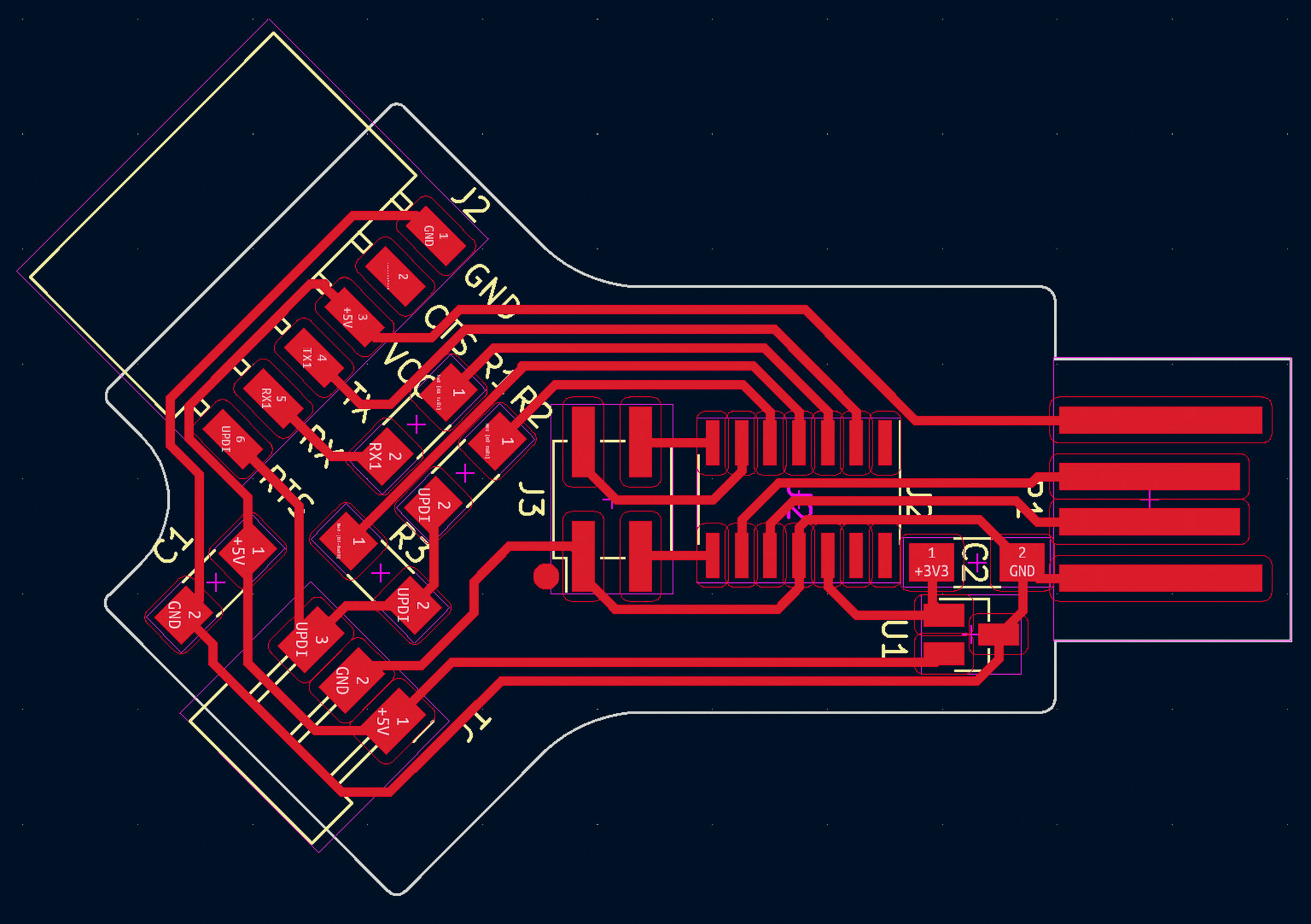
Dual serial board 
In a previous week I made a USB to serial & UPDI in one board.
With that board it’s possible to select USB to serial or UPDI mode with a slide switch.
In the meantime Quentin designed a SAMD11 dual serial board. By using this approach there is no need to switch modes - one can simply use one serial interface for serial communication and the other for UPDI.
I took Quentin’s design as a starting point and modified it to have a UPDI connector instead of a second FTDI one.
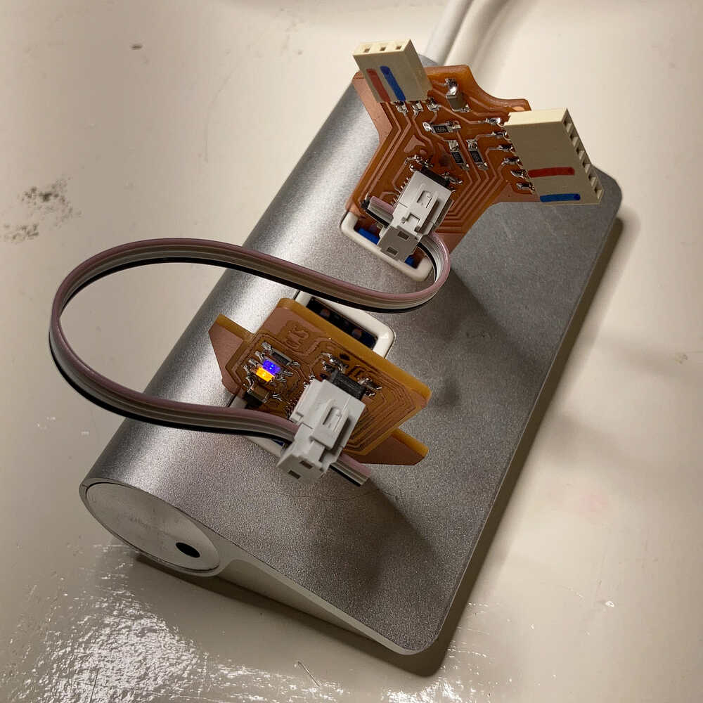
edbg on M1 mac
I tried to use edbg to load Quentin’s firmware onto the board but my installation of edbg wasn’t working properly. Fortunately Matti already solved this issue and documented the solution :-)
Once I reinstalled edbg following these steps I managed to load the firmware onto the board using this command:
Retrospective
I’m really happy with the outcome of this week.
The bike heliostat prototype puts me in a good position to test different sensors and control approaches for my final project in the coming weeks.
I’m excited about the dual serial board as it will make programming and debugging easier as there is no more need to plug boards in an out.
While working on the bike heliostat I designed the parts one by one but I did not make an assembly where all of them are together. When I assembled things physically one of the brackets was in the way of the GT2 belt. Having all the parts together in one design would help to prevent surprises during physical assembly.