3. Computer Controlled Cutting
Planning
Tasks - Must
- Group assignment: Characterize your laser cutter’s focus, power, speed, rate, kerf, and joint clearance
- Cut something on the vinyl cutter
- Design, laser cut, and document a parametric construction kit which can be assembled in multiple ways. Account for the laser cutter kerf
Tasks - Nice to
- Create a flexible circuit with the vinyl cutter
- Upgrade my final project prototype - sun tracker
Execution
Laser cutter
Overview
In our fablab we have a BRM laser cutter with a 1600X1200 mm bed and a 100W CO2 laser. The laser cutter itself is pretty old but the controller was recently substituted and is controlled by LightBurn.
Operation
Turn on machine
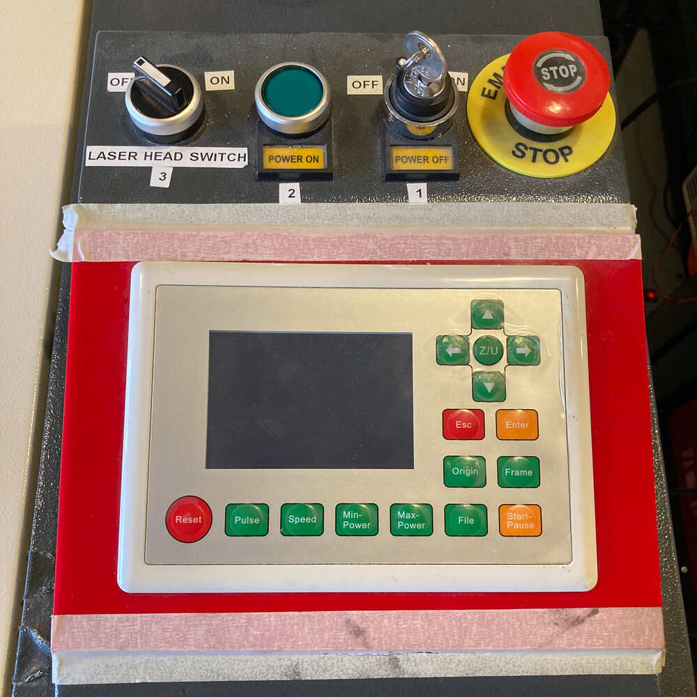
- Turn key marked with
1 - Press button marked with
2
Clean the bed
If there are parts left on the bed, the material to cut won’t lay flat. It’s important for the material to lay flat on the bed to have a constant laser focus
Place material
Make sure material is laying flat on bed. For materials which might not be perfectly flat like cardboard it can help to add weights
Open lightburn
It’s important to do this AFTER the machine was turned on other-ways Lightburn won’t communicate with the machine
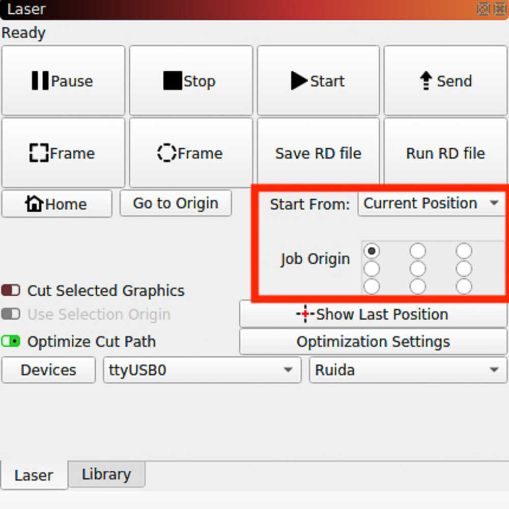
Set origin
Move laser head to position where you want to start with cut by using move buttons in lightburn
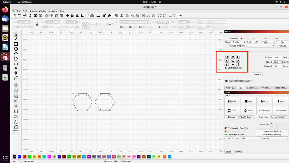
In Laser section:
- Set
Start fromtoCurrent Position - Set
Job Origindepending on where you want to cut relative to the head’s position
Set cut parameters
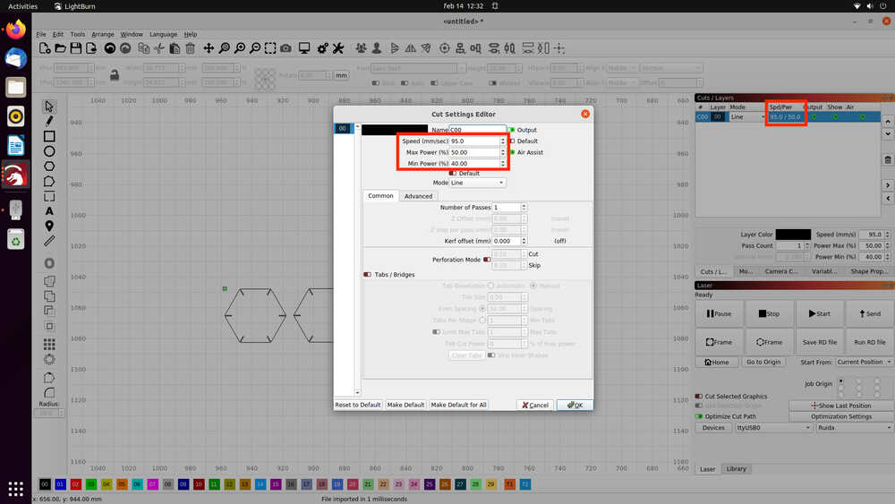
Click on the parameters in the Cuts / Layers section and specify parameters in the Cut Settings Editor:
Speed: Speed at which the laser head will move. Consult test cut library next to laser cutter to find a suitable valueMax Power: Power of the laser. Consult test cut library next to laser cutter to find a suitable valueMin Power: 80% of Max Power is a good starting point for this setting. This is the power used when the laser slows down to go around corners.
To use multiple settings on one design (e.g. one for cutting and one for engraving): Use multiple colors in drawing and configure parameters for each color
Focus laser
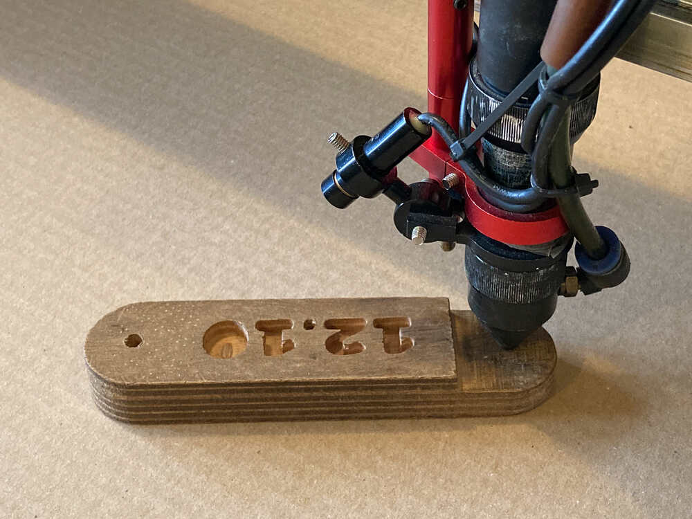
- Place focusing spacer on top of material to cut
- Unscrew laser head
- Push laser head down onto spacer
- Tighten laser head screw
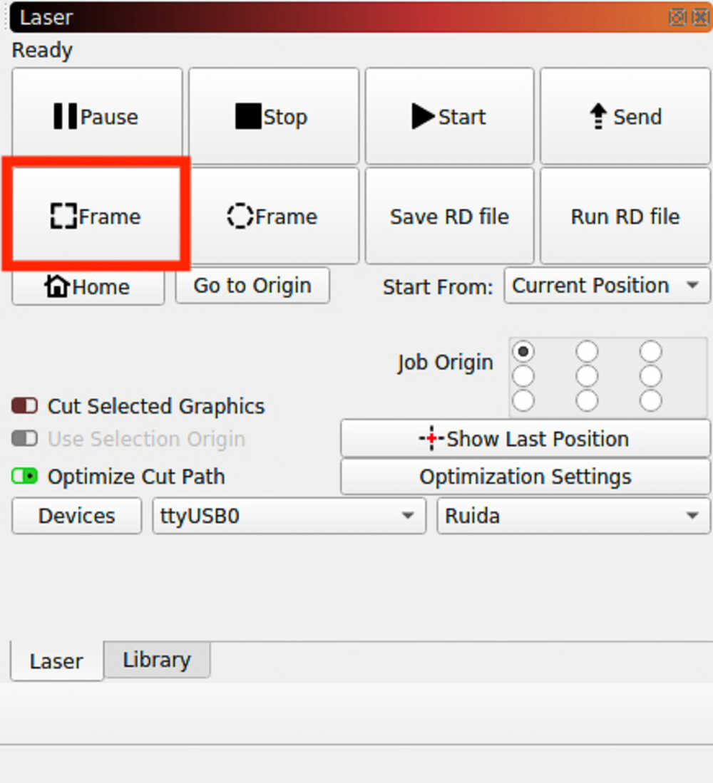
Frame
Click the Frame button to get the head to move around the area it will cut. This helps to see if the cut will stay within the material
Turn on laser and fume extractor
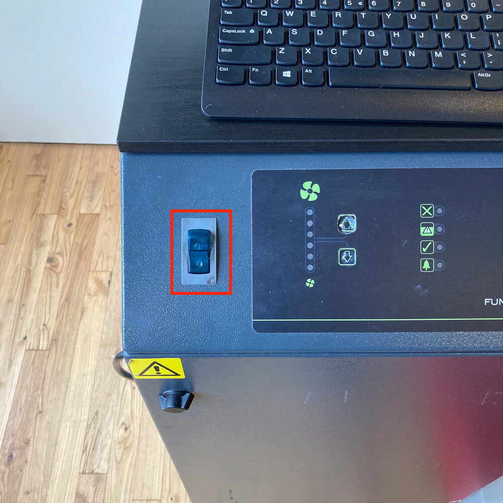
- Turn on laser by turning switch marked with
3toONposition - To turn on air extractor / filter using switch highlighted in image
Start Job
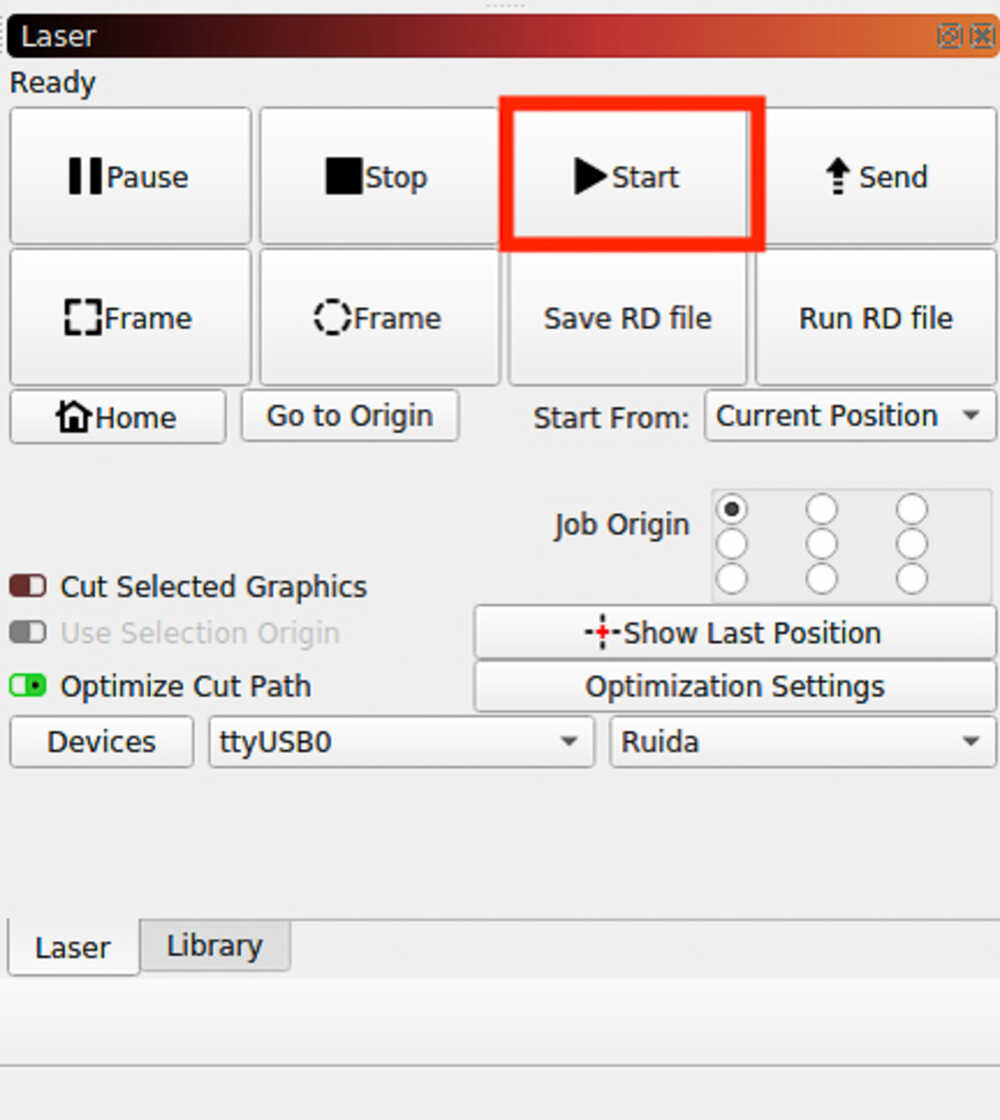
Stay in red area
It’s important to stay next to the machine while it’s running
Safety
- Don’t leave the laser cutter unsupervised while it’s running. Stay in read area.
- Water spray to extinguish small fires is next to laser cutter
- Fire extinguisher is next to sink
Group assignement
Together with Bente we decided to experiment with the laser cutters parameters using 2.2mm acrylic.
Power and speed
In order to start cutting we have to find an appropriate speed and power for our material.
In our lab we have a “library” of materials where you can see the effects of different powers and speeds on a certain material. We found example cuts on 2mm acrylic in our “library”.
We decided to try speed 25, power 75 as this combination did cut through the “library” example.
We made a small test cut and it worked :-)
Kerf 
Next we want to find out the laser’s kerf width when cutting our chosen material.
When the laser cuts through the plate it removes a small amount of material. The so produced groove is called kerf and we want to find out how wide it is.
We could just cut a square and measure how big it is and then calculate kerf = dimension in drawing - real dimension
We saw that in the last years they did cut multiple rectangles and measured them together. This sounds like a good idea as the kerf width might not always be exactly the same and this will give us a mean over multiple cuts.
We created an OpenSCAD snipped that draws 10 squares, exported it as SVG and made the cut.
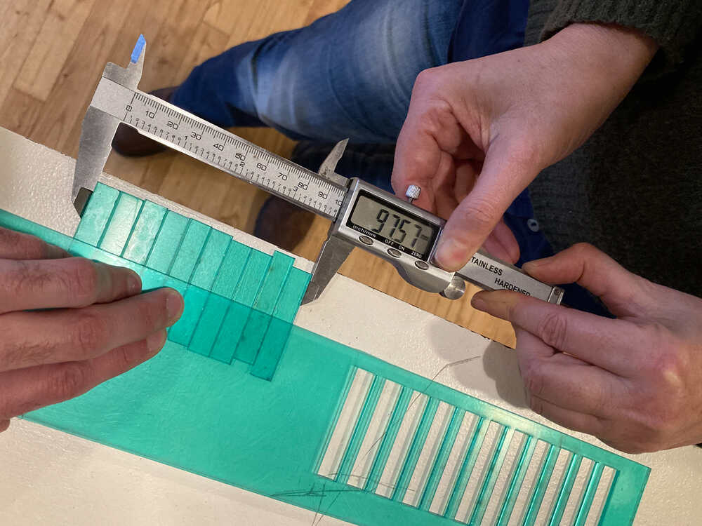
Once we had the rectangles we measured them all together and calculated the kerf width as follows:
Kerf width = (100 - 97.57) / 10 = 0.24 mm
Fail
At first we measured our rectangles and were really surprised that the total was > 100 mm. We soon realized that we had 11 rectangles instead of 10. We made a classic for loop limit error in the OpenSCAD program
Press fit joint 
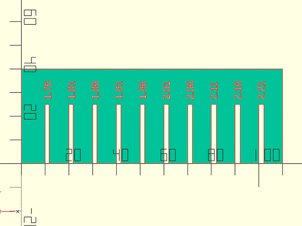
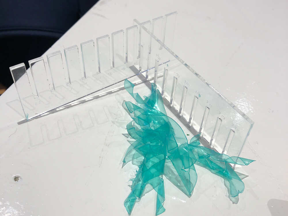
Now that we know the kerf we’re ready to design a press fit joint. In theory if we make a cutout of 2.2 - 0.24 = 1.96 mm our acrylic plate should fit perfectly in it. Theory might not be perfect and it would be useful to test the fit of joints with multiple clearances. To do so we designed a press fit comb. Each cutout of the comb is 0.05 mm wider than the previous one.
Fail
When we tested the join fits we realized that there was a protective foil on the acrylic. We did not take the thickness of this foil into consideration when we made the previous steps. Because we had quite some options on our combs we still found a good fit. It was just one of the narrower cutouts instead of the central one as expected
Fail
When cutting the comb with cutting and engraving lines at the beginning we were cutting before engraving. After cutting the part moved slightly and therefore the laser was a little bit out of focus when engraving. We learned that it’s good habit to engrave before cutting
Construction kit 
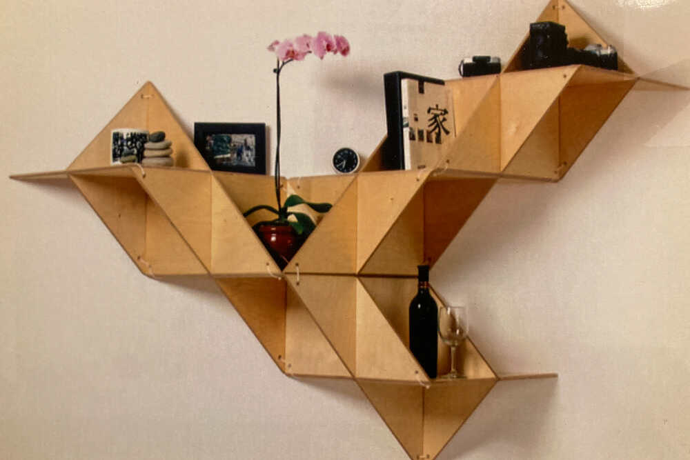
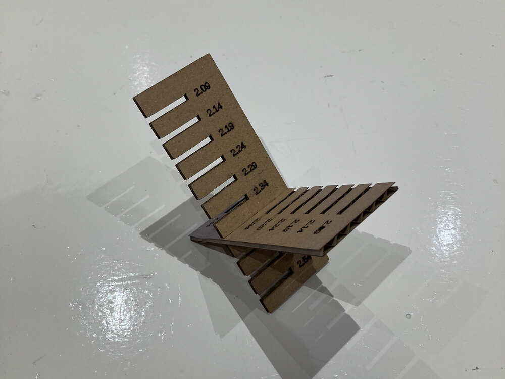
A while ago I found this picture on the internet. Unfortunately I can’t remember where. I really like the look of this construction even if it would just be an object and not used as a shelve. I want to make a construction kit that can be used to construct a similar object.
Laser cutter parameters
In the group assignment we found appropriate parameters to work with 2.2 mm acrylic. As I will cut my parametric construction kit out of 2.7 mm cardboard as a first step I will have to find speed, power, kerf and joint clearances for this material.
Based on the lab’s laser cutter “library” I decided to start by using
speed 100, power 50for cuttingspeed 100, power 10for engraving labels
I made some test cuts and the cutting parameters worked straight away. The engraving ones needed a bit of try and error. In the end I made the labels bigger and settled on speed 100, power 12.
I re-used the OpenSCAD code from the group assignment to cut kerf check squares and press fit combs. I just had to adjust some variables for the comb as the cardboard has a different thickness than the acrylic used in the group assignment.
I measured and calculated kef width = 0.21 mm and the press fit comb hat a nice and tight fit at the 2.4 mm cutout.
Fail
At the start I measured the cardboard only in one corner and there it was 2.5 mm thick as it was apparently a bit squashed. Later I made more measurements and found out that there is quite some difference between measurements (around +/- 0.2 mm). The mean of this measurements was 2.7 mm. From now on I will use 2.7 mm as the base thickness instead of 2.5 mm
Fail
When cutting a press fit comb at some point the laser was cutting wiggly lines. After a bit of trouble shooting I found out that someone was experimenting with the kerf offset setting in Lightburn and I forgot to set it back to zero. Michelle confirmed that the kerf offset setting doesn’t work properly and leads to wiggly lines
Design
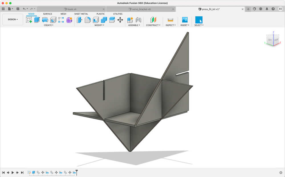
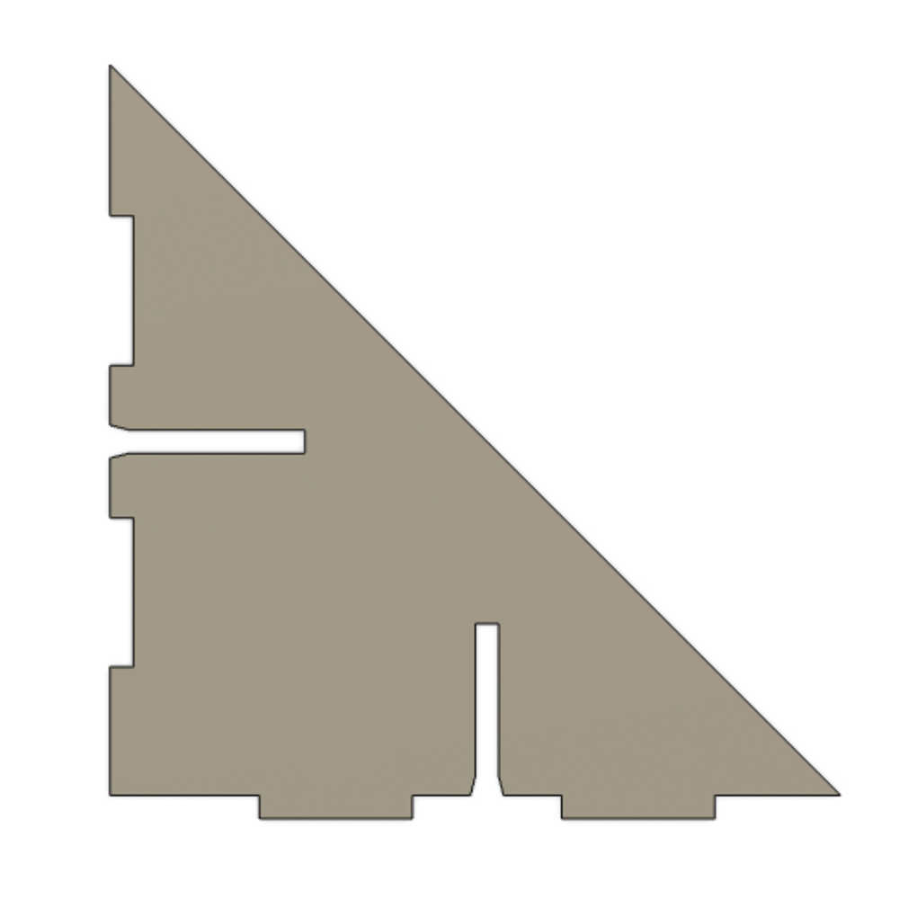
In fusion 360 I designed parametric triangles with cutouts so that they can be jointed to each other.
To check how it looks when they’re jointed I created multiple copies of them and aligned them (Design > Solid > Modify > Align)
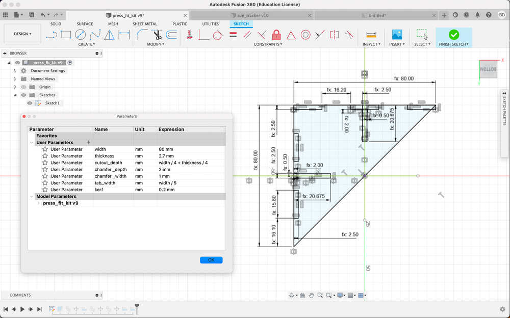
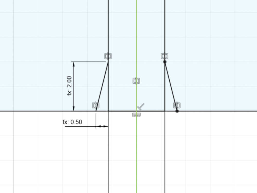
At the entrance of the cutouts I added a chamfer to make easier to push the triangles into each other.
Fail
I exported the fusion 360 drawing as PDF but I was not able to import it into lightburn. I tried PDF to avoid DXF as Neil suggested to avoid it if possible. As I had no other options I exported DXF and I was able to successfully import it into lightburn
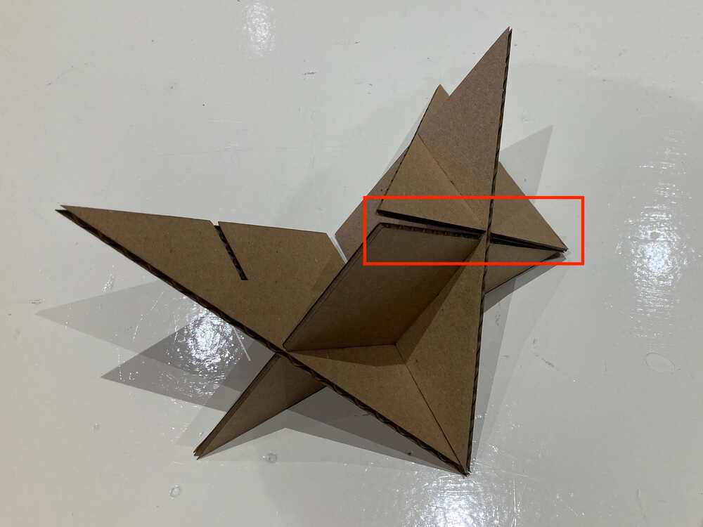
I cut out a couple of triangles to assemble a first prototype. It’s hard to keep the edges of the triangles aligned. I’ll have to find a solution to improve that.
I managed to improve the alignment by adding finger joints to the two legs of the triangle.
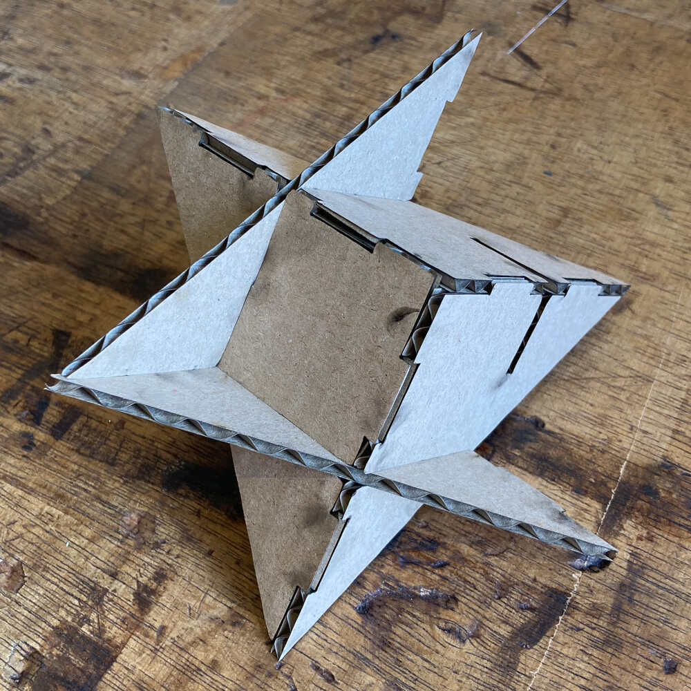
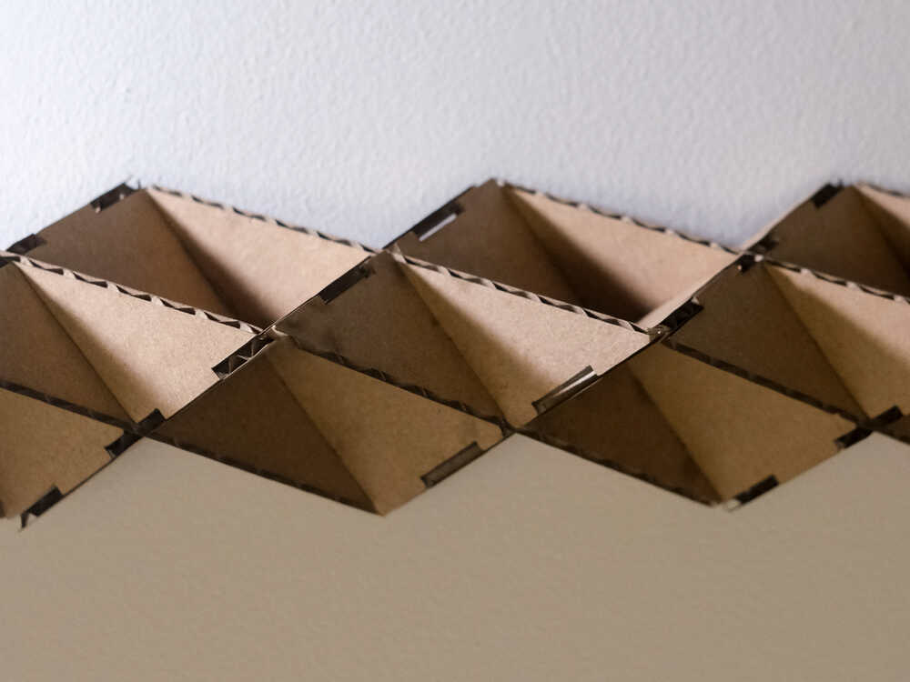
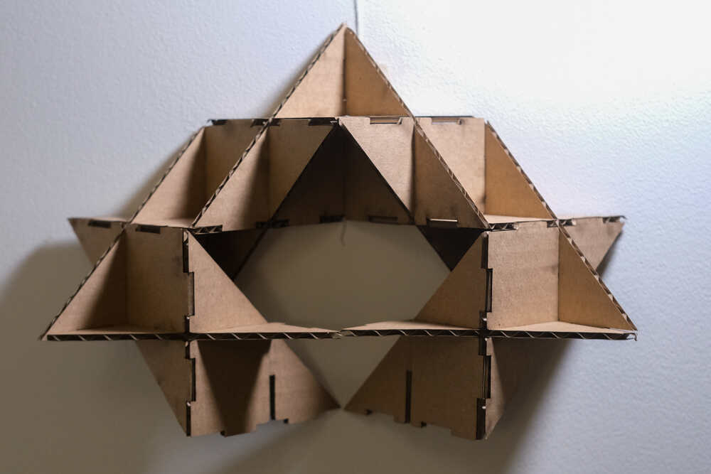
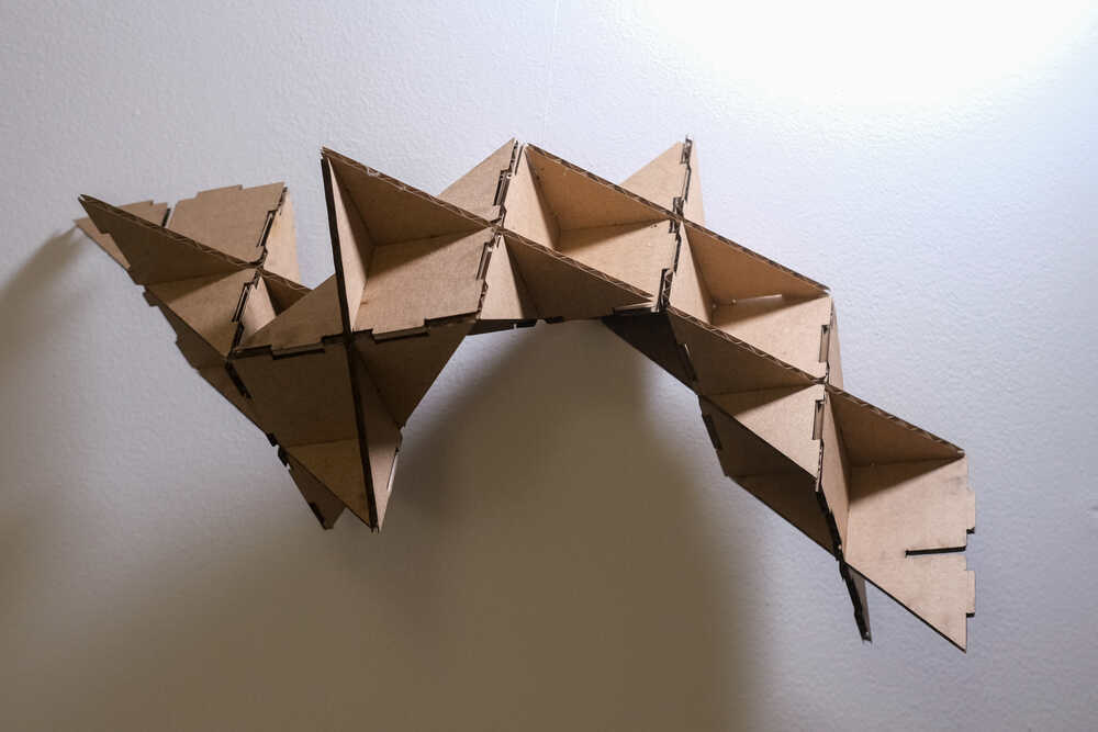
Once I was happy with how the edges of this version aligned I did cut more triangles and started creating some constructions :-) These are some objects I created with my construction kit:
Vinyl cutter
In our fablab we have a Roland GX-24 vinyl cutter
Preparation
Turn on & insert vinyl from back
- Press power button to turn on.
- Little pieces can be inserted from the front too but it’s good habit to always feed in material from the back
Adjust rollers & lock down material
The rollers hold down the material. They can be adjusted right/left from the back of the machine
They have to be within the white markers other-ways the machine will give a BAD POSITION error
Use the lever on the right backside of the machine to lock the material in place
Select Roll or Piece
Make selection on display using buttons
- When
Pieceis selected the machine will measure the dimensions of the piece - When
Rollis selected only the width is measured
Set origin
Move head to desired origin position and press ORIGIN button
Make test cut and adjust force if necessary
Press TEST to make a test cut and check if the cut piece can be peeled off easily using tweezers.
If the material was not cut properly, press the FORCE button to adjust the force with which the knife is pushed towards the material
Cut
Fail
First I tried to control the vinyl cutter with the inkscape inkcut extension but when I sent jobs to the machine this way it ended up cutting travel lines. While on a travel line the knife should move but not cut.
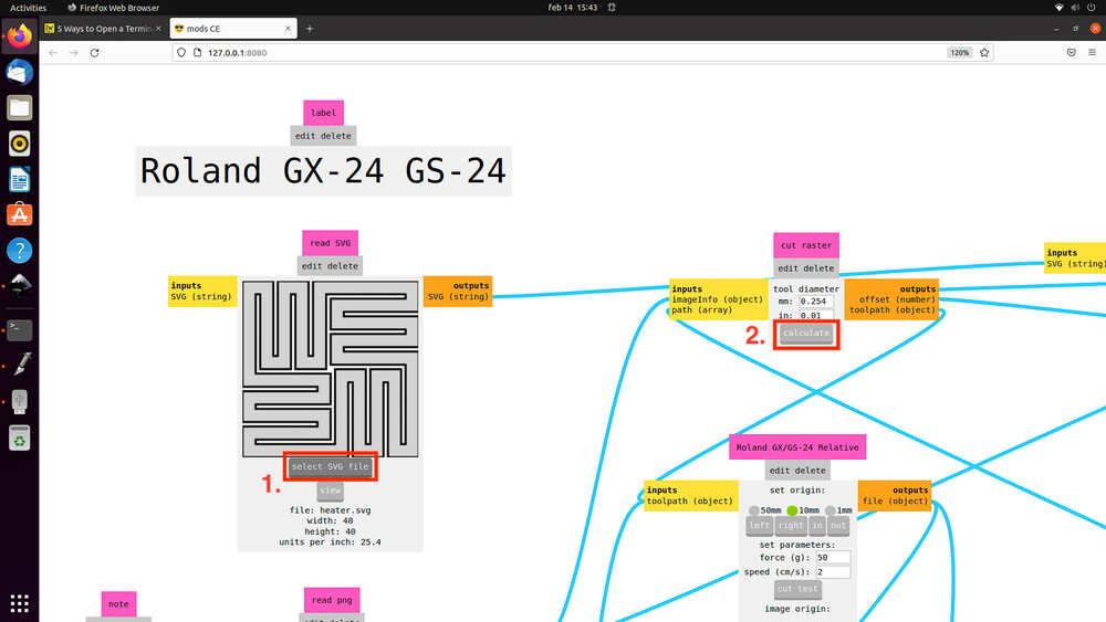
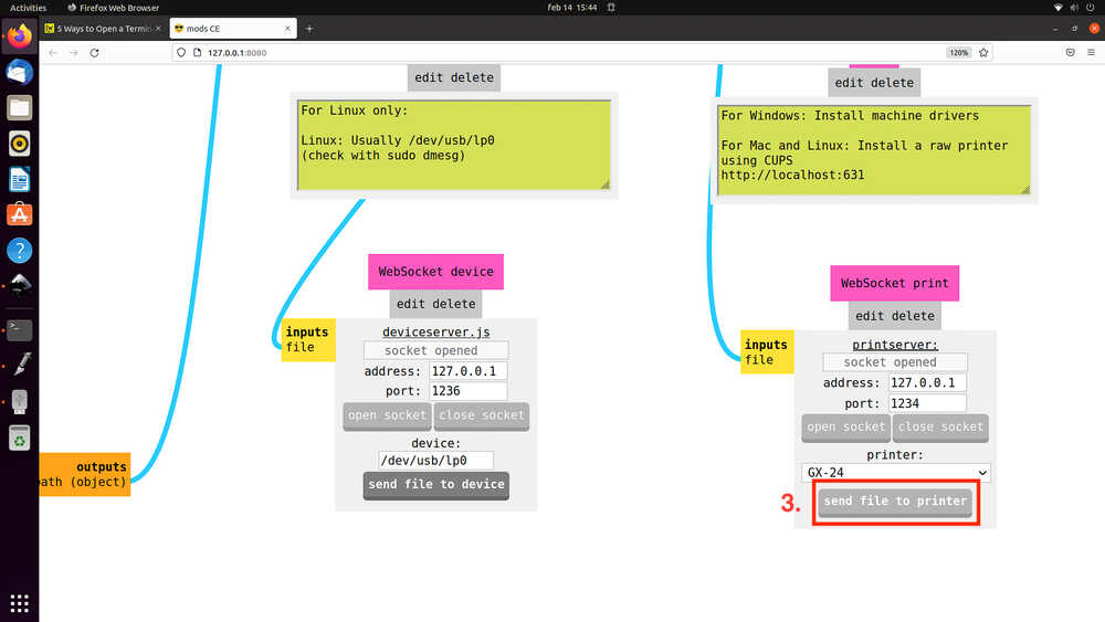
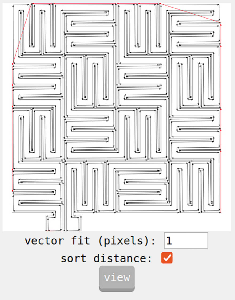
My second attempt was to use mods:
Fortunately our vinyl cutter was already configured in mods. To print my design I followed these steps:
- Load SVG
- Calculate
- Send file to printer
Flexible heating pad 
I saw this video from Carl Bugeja where he designs flexible heating circuits and I wondered if I could make something similar on the vinyl cutter.
As there are quite a bit of things to figure out before I get to a flexible circuit that keeps my coffee warm I will approach this in steps. This is my plan:
- Design small section of the circuit
- Make a vinyl sticker (It’s easier to get a good result with vinyl than with copper tape)
- Make a small circuit with copper tape
- Make full size circuit with copper tape
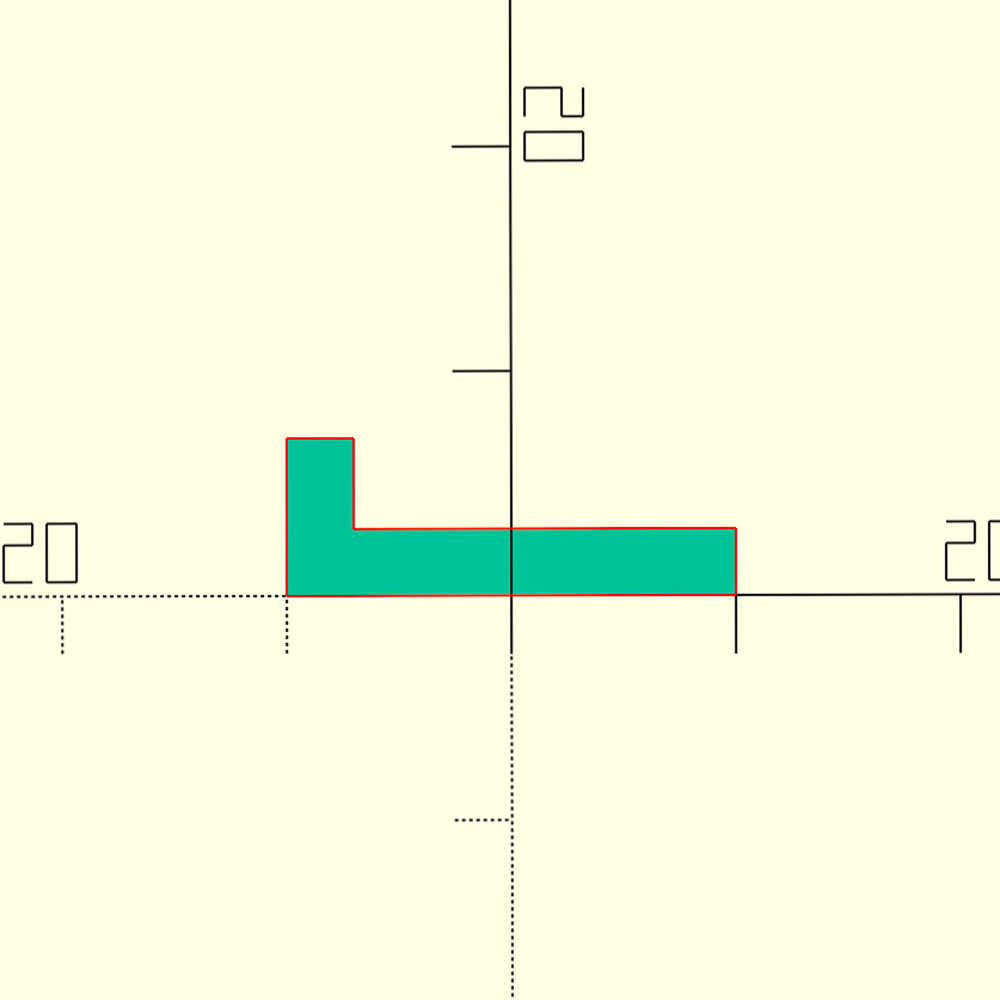
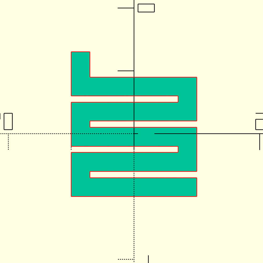
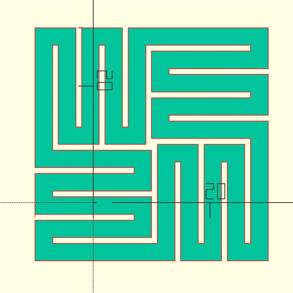
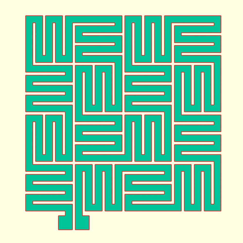
As the circuit will consist of a simple shape repeated over and over in different orientations I decided to draw it in OpenSCAD. The code creates the 2D model by:
- Create
Lshape - Repeat
Lshape multiple times in different orientations to form aunit - Repeat
unitmultiple times to create acircuit. Well… this is not a meaningful circuit yet but I like the look of it and I will take it as a first model to cut on the vinyl cutter :-)
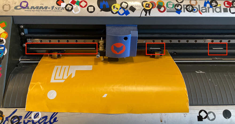
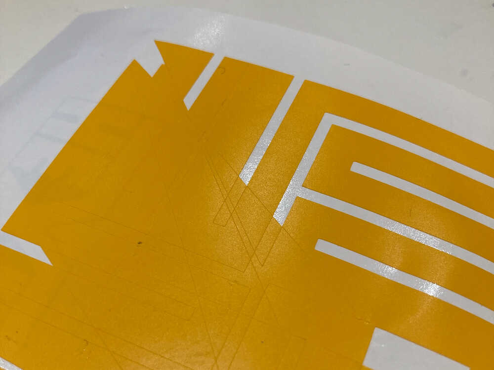
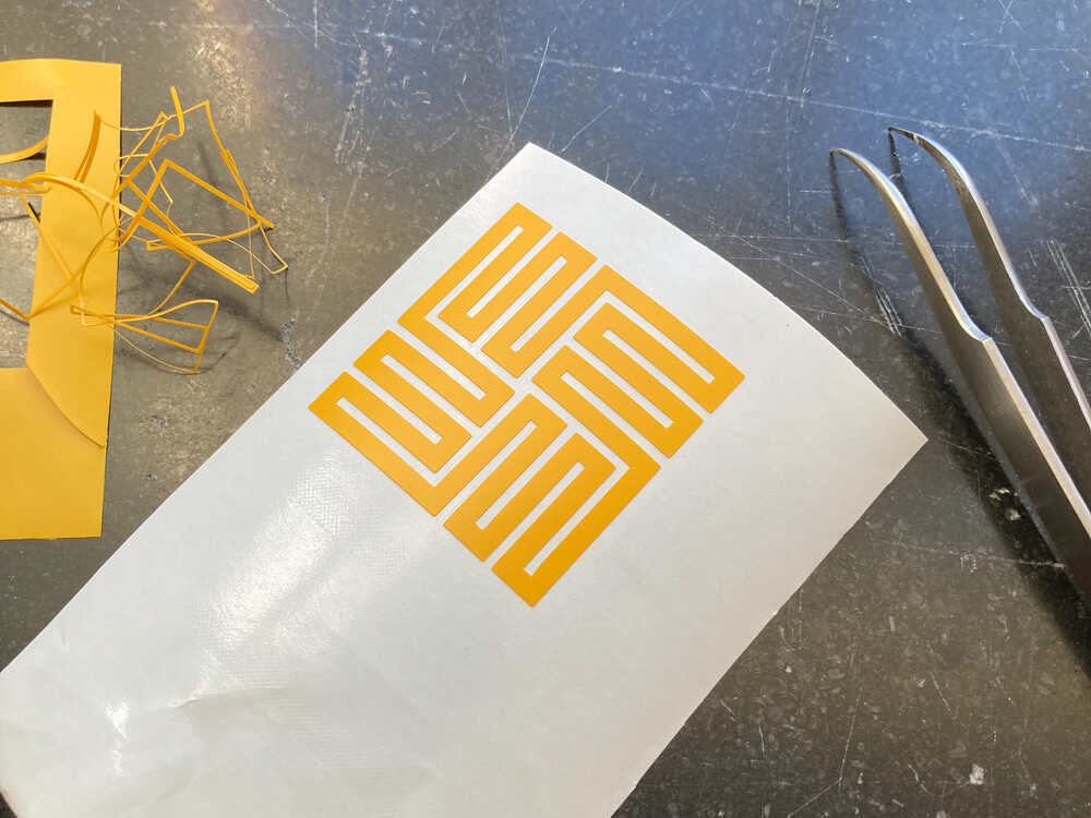
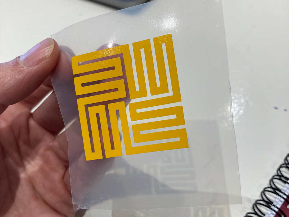
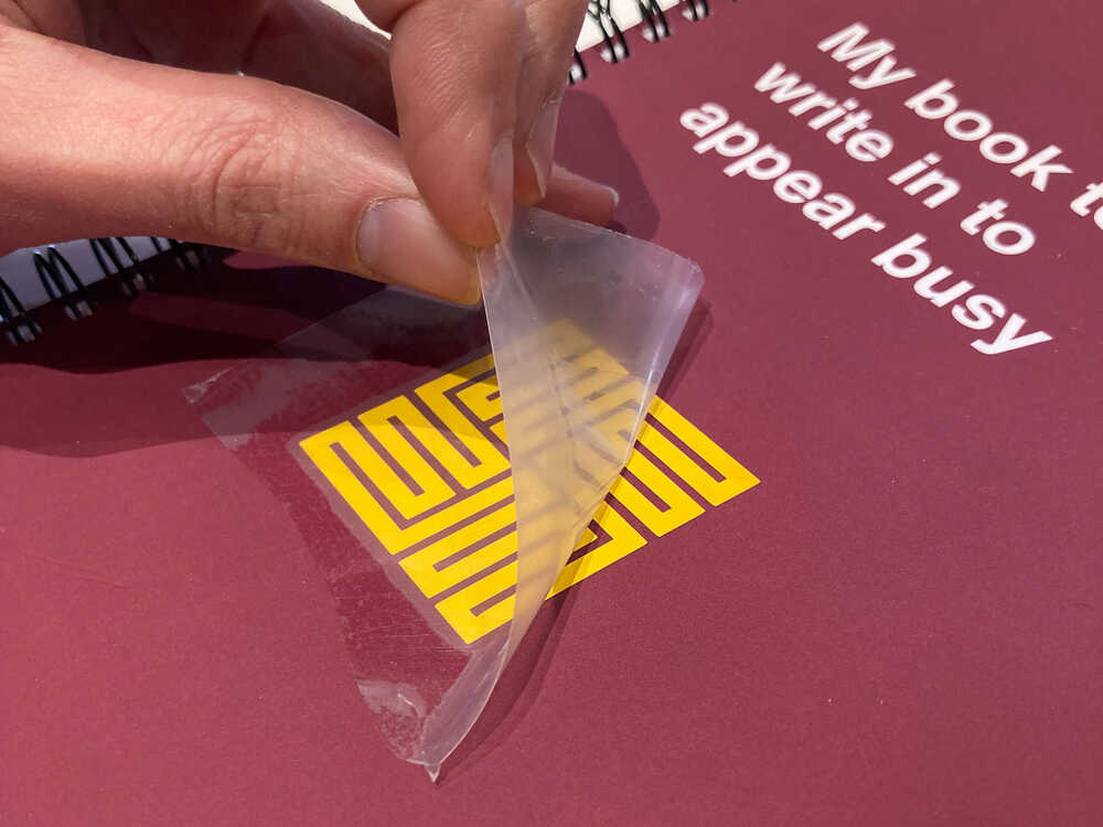
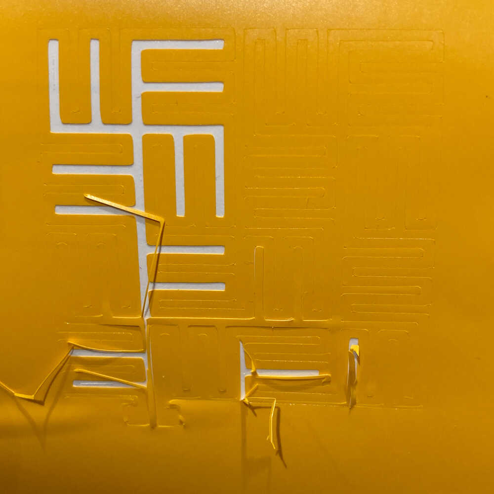
After cutting, weeding, putting on transfer tape and applying I ended up with a nice sticker on my notebook. I really like how it looks.
At this point I created a second design with a longer trace and pads to connect to and I started by trying to cut it in vinyl.
Fail
I did not manage to cut this design. The machine pulled up the vinyl from the backing material multiple times. When I took a closer look at mods I saw that it was generating more cutting lines than necessary. It looks like the knife pulls up the vinyl when it’s doing the extra (unnecessary) cuts. Michelle explained that this is happening because my SVG has a shape with a wide (0.5 mm) outline and mods is generating cutting lines for the inside and outside of the outline.
I did look for SVG export options in OpenSCAD but I couldn’t find any. I will try to adjust the stroke of my SVG by opening it in a text editor and adjusting the XML directly.
I did not manage to try the adjusted SVG as I did run out of time at this point.
Sun tracker 
Last week I’ve modeled and built a first version of my final project: A simple servo pan tilt head. This week I’d like to upgrade it to be a solar tracker.
The mirror of my final project won’t point towards the sun but to position it correctly the sun’s position needs to be known. A sun tracker unit might be an option to determine the sun’s position.
I plan to build a sensor to detect where the sun is (or rather where most light is coming from) and write a program to adjust the pan tilt head so that it points in that direction.
I designed a cross structure in fusion 360 which consists of 3 laser cut parts jointed to each other. I made a test cut in cardboard first to see if things fit together and then made a version in plywood.
![]()
In each of the 4 cross sections I will mount a photoresistor. By measuring which ones are in the light and which ones are shaded by the cross structure I can infer where the light is coming from and then move the head accordingly.
![]() The electronics will be quite simple. Each photoresistor will be paired with a resistor to form a voltage divider. Be doing so the voltage between the two components will vary when the photoresistor resistance changes. I will then measure this voltages with analog inputs of the microcontroller, infer the sun direction and control the servos with a PWM signal accordingly.
The electronics will be quite simple. Each photoresistor will be paired with a resistor to form a voltage divider. Be doing so the voltage between the two components will vary when the photoresistor resistance changes. I will then measure this voltages with analog inputs of the microcontroller, infer the sun direction and control the servos with a PWM signal accordingly.
![]()
I started by prototyping the circuit on a breadboard.
![]()
Once the circuit on the breadboard worked I started building a circuit on a stripboard which can be directly mounted to the laser cut shade structure.
Retrospective
It’s been a really exciting and intensive week. There were so many things to experiment with and just not enough time to do everything. Every time I tried something I had multiple ideas of other things to try out. I hope to be able to pick up some of the ideas again in the future.
- It was amazing to start using the machines in the lab
- The individual assignment was really open: It was a nice challenge to come up with a design and it was super interesting to see what other people came up with
- For my vinyl cutter project I had a final goal but I was aware from the beginning that it would be difficult to reach: It was helpful to come up with multiple intermediate goals that get more difficult and closer to the final idea over time