12. Input devices
Planning
Tasks - Must
- Group: Probe an input device(s)’s analog and digital signals
- Measure something: add a sensor to a microcontroller board that you have designed and read it
Tasks - Nice to
- Use motor back-EMF as input for homing
- Interface sun tracker with nacho breakout board
- Measure mirror angle and direction with accelerometer and compass
Execution
Group assignment
I won’t be able to make this assignment in a group as I will be working from home this week as I tested positive to COVID. I will do it by myself instead.
I will be using the Analog Discovery 2 USB oscilloscope to probe the signals.
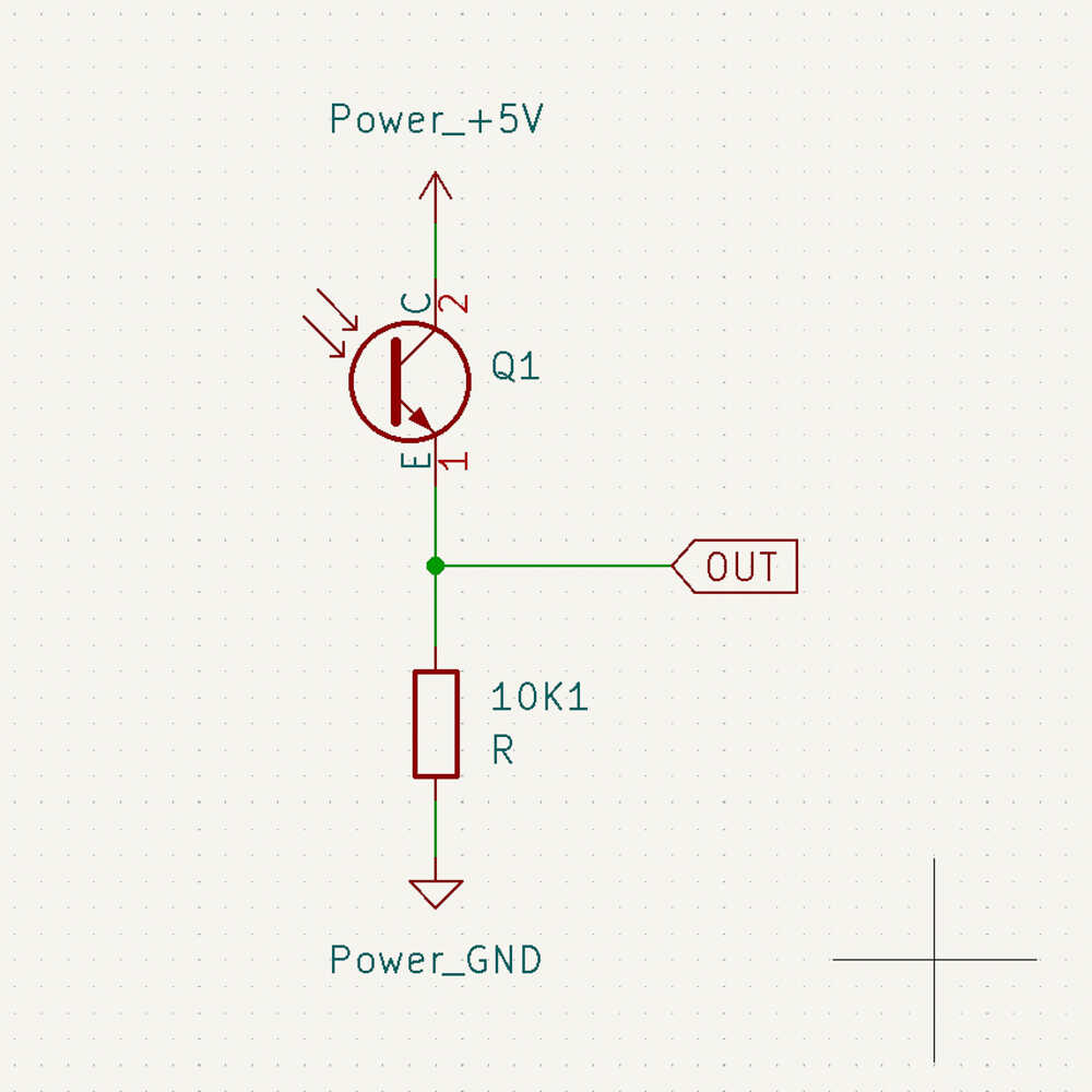
Analog signal
I probed the output of a Photo Transistor using this simple circuit:
Digital signal 
I’m going to use a BH1750 ambient light sensor with I2C interface (breakout board). I will intercept the I2C communication and try to interpret it.
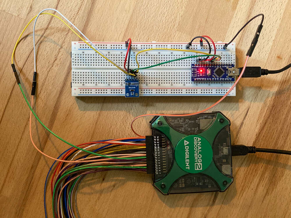
I connected the light sensor to an arduino nano. On the arduino there is some code which continuously reads the light value from the sensor via I2C.
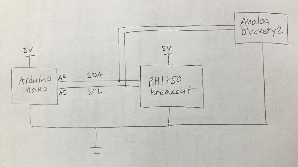
Then I connected the USB oscilloscope to the I2C SCL and SDA lines to “spy” on the communication.
WaveForms (USB oscilloscope software) has Protocol analyzer functionality which supports I2C with which it was super easy to capture the I2C communication.
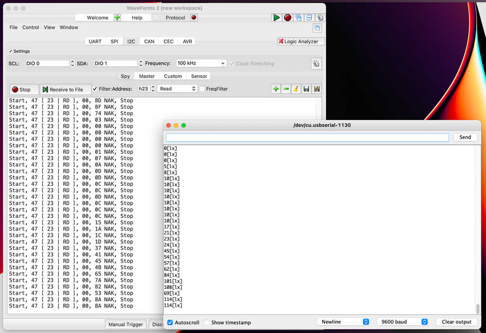
In the screenshot the left window is the WaveForms protocol analyzer and the right window is the serial output of the arduino sketch which outputs the light values received from the sensor.
The I2C communication is easy to capture but it’s a bit more difficult to make sense out of it. To understand what’s going on I’d have to dive deeper in the BH1750 datasheet to figure out in detail how the sensor returns the light reading. I’m not going to do that right now.
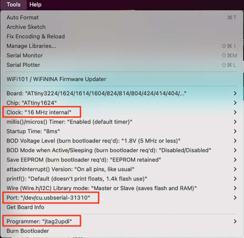
Improvising a new UPDI programmer
When I wanted to program my board I realized that my programmer stopped working. Not sure what happened to it. As I’m working from home these days I don’t have the setup to make a new programmer board. As a workaround I modified an arduino nano to act as a UPDI programmer with the steps described in this tutorial
Once I was done modifying the arduino nano I was able to use it as a programmer with the following settings:
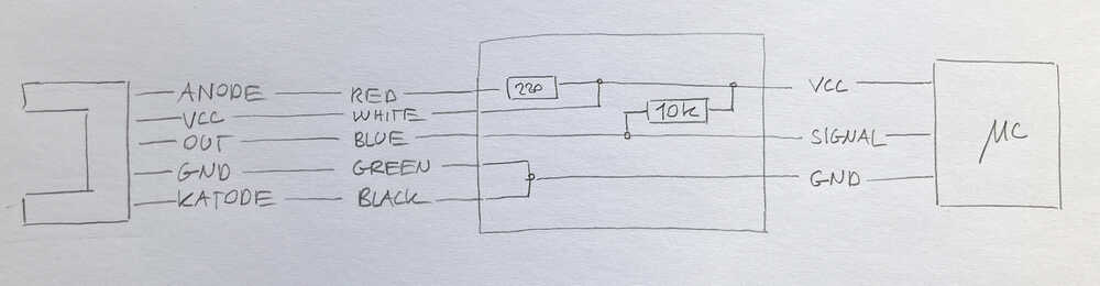
Light barrier 
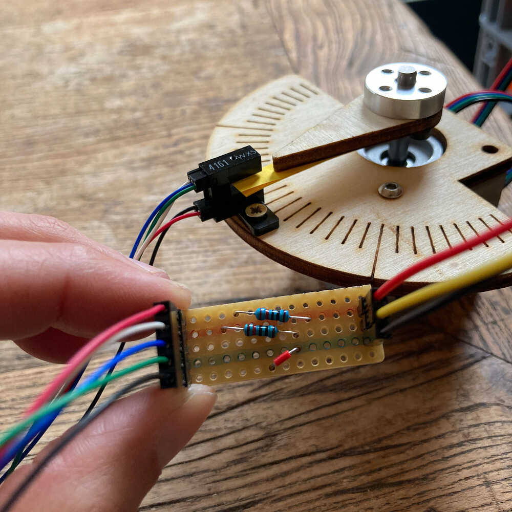
I’m going to use a stepper motor and a light barrier. I plan to use the light barrier to detect when the pointer attached to the motor shaft is passing by.
There are 5 cables coming out of the light barrier. I’d like this to be simpler: I’m only interested in VCC and GND to power the light barrier and a SIGNAL to see if the barrier is interrupted or not. I made a little adapter board that provides this simpler 3 connector interface.
This is the setup with the stepper and the light barrier:
I wrote a simple sketch that continuously rotates the motor. It does as well check the status of the light barrier and outputs it to serial.
The video shows how the serial output changes (arduino IDE serial plotter) when the motor pointer interrupts the light barrier:
Retrospective
During the first days of this week I had COVID. After some days I felt better and I was able to work on the assignment from home. I missed coming to the lab and being able to use the machines but I still managed to make some interesting experiments with the sensors I had at home.
As I wasn’t able to make a new board I was super happy that I made a generic breakout board in the output devices week that I was able to reuse for this assignment.
I wanted to experiment with an accelerometer/compass sensor as this might be useful for my final project. Unfortunately I did not have such a sensor at home. I’ll experiment with such a sensor in the coming weeks.