Development
Positioning
How do I know at which angles to position the mirror to reflect the sun to a certain point and how do I move it there?
I’ll have to build a structure that allows the mirror to be moved in two axes.
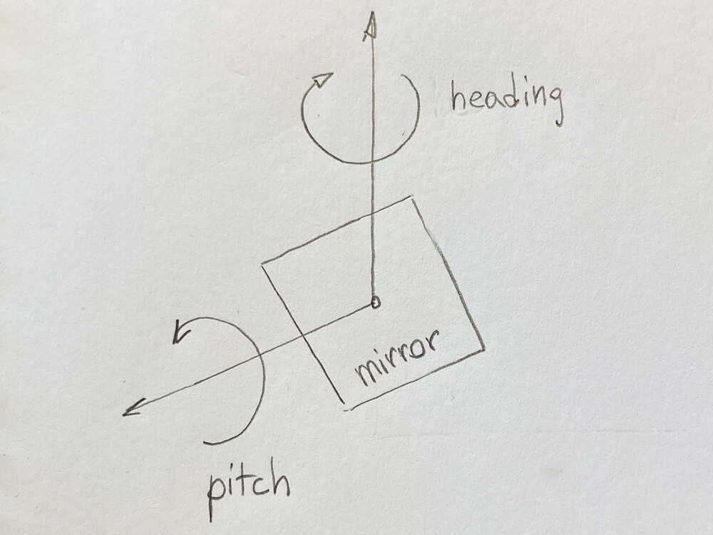
HEADINGwill determine in witch direction (horizontal angle) the mirror is pointing e.g. SOUTHPITCHwill determine at what vertical angle the mirror is
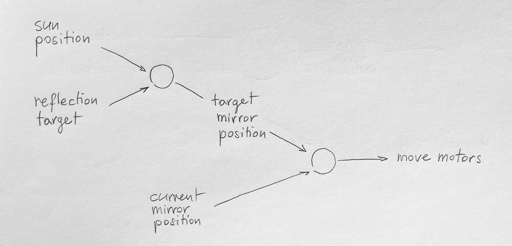
Do determine how I have to move the motors I need know the position of the sun, where the sun should be reflected and the current mirror position. In the following section I will look at each of these aspects in more detail:
Sun position
There are multiple options to know the sun’s position:
1. Use library to calculate sun position
This javascript library makes it easy to calculate the sun’s position. I decided to use this approach for my final project. By doing so I don’t need an internet connection or an extra sensor.
2. Call an API
Call an API to get the sun’s position for my location/date/time. The suncalc.org API seems to be a good starting point.
3. Position table
Use online resources to create a table of the sun’s position for my location based on date/time and store it on my controller. This is similar to the previous approach just that I store the positions offline.
4. Measure
Use a sensor to measure the sun’s position.
There are accurate sun angle sensors used in aerospace but they’re really expensive.
I’ve built multiple sun trackers that continuously adjust to point towards the sun. I could use such a device to measure where the sun is. The downside is that the ones I’ve built aren’t really accurate and they consist of multiple components/moving parts that would add complexity to the system.
Reflection target
Where should the sun be reflected to?
The reflection target has to be known to the controller. I’m going to support a target setting mode. When this mode is activated the user can make the heliostat reflect the sun to the target by controlling it’s positioning manually. When exiting this mode the controller stores the reflection target and will adjust itself automatically to continue reflecting there.
Current mirror position
To move the mirror to certain angles, first of all I have to know it’s current position. I can think of two approaches:
1. Home steppers and keep track of position
- Position the base of the heliostat in a predetermined way. e.g. the base perfectly level and the front pointing SOUTH.
- Home the stepper motors when the device is turned on
- Keep track of the mirror orientation based on the steps performed by the motors
I decided to use this option for my final project to keep things simple but in the future it would be interesting to experiment with approach 2.
2. Use a sensor to measure the mirrors orientation
Measure the mirror position using an absolute orientation sensor like the BNO055.
If I use this approach it would be much easier to move the heliostat around. Here I made some experiments to check if the BNO055 is accurate enough for my application.
Lemur - the desktop heliostat
I’ll call my heliostat lemur as these friendly animals like to sunbath :-)
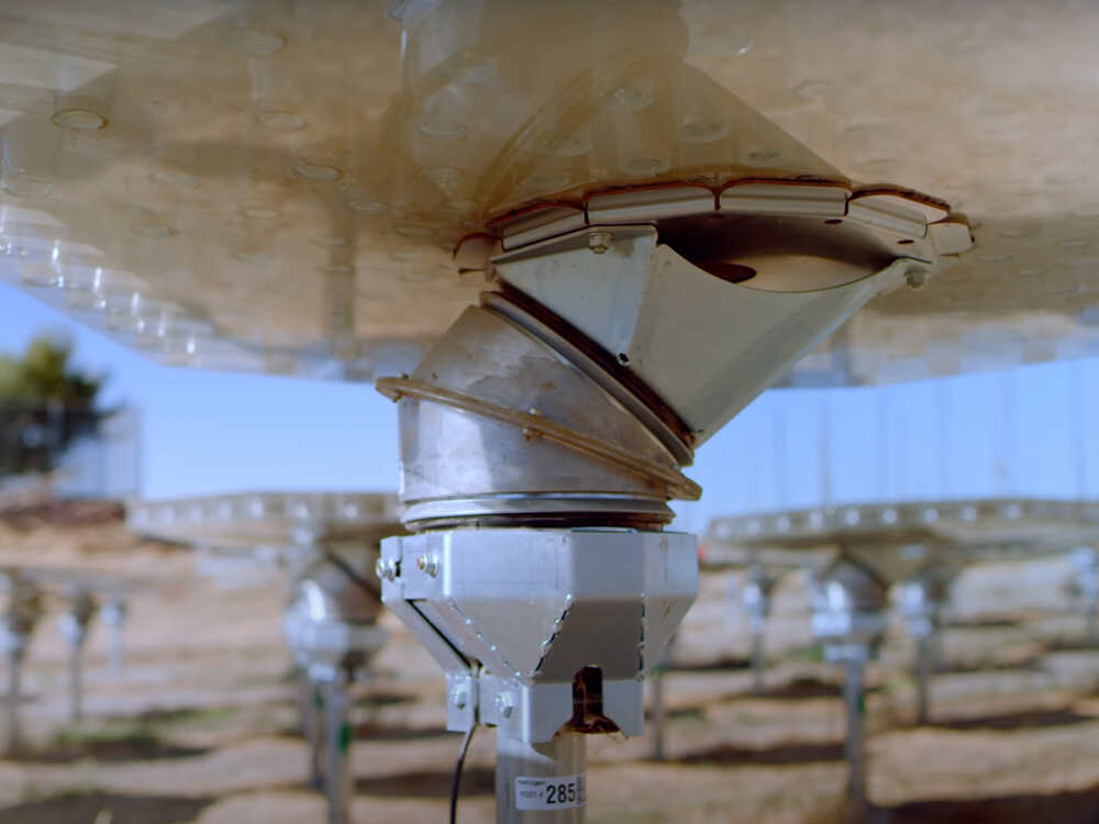
I saw this video about heliogen and I really liked the mechanism they use to move their heliostats so I decided to build something similar.
Figuring out angles 
To reflect the sun to a target, the mirror has to be positioned half-way between sun and target angle. If we just consider the heading (horizontal) axis that means that if the sun is SOUTH and the target EAST, ill have to position the mirror direction SOUTH-EAST.
Heading (horizontal) axis:
The heading range is pretty straight forward.
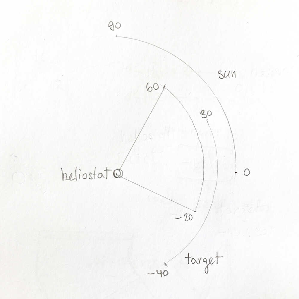
The sun rises EAST and sets WEST. That means that the heliostat has to be able to move between SOUTH-EAST and SOUTH-WEST, that’s a range of 90°
Pitch (vertical) axis:
- The sun moves between
0°and90°during the day - I decided that it should be possible for the target to be between
-40°and30° - That means that the heliostat should be able to move between
-20°and60°
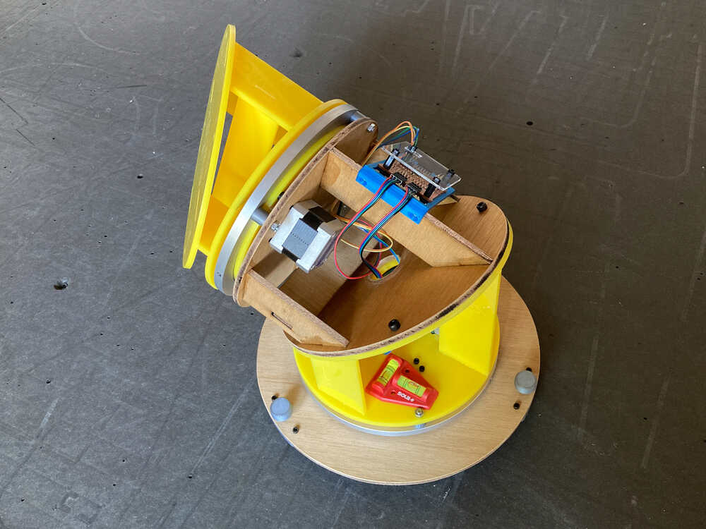
The structure of the heliostat is going to be composed of 3 parts (numbered in image below). To experiment with the angles of the 3 parts and get a better feel on how this mechanism is going to work I printed some small prototypes.
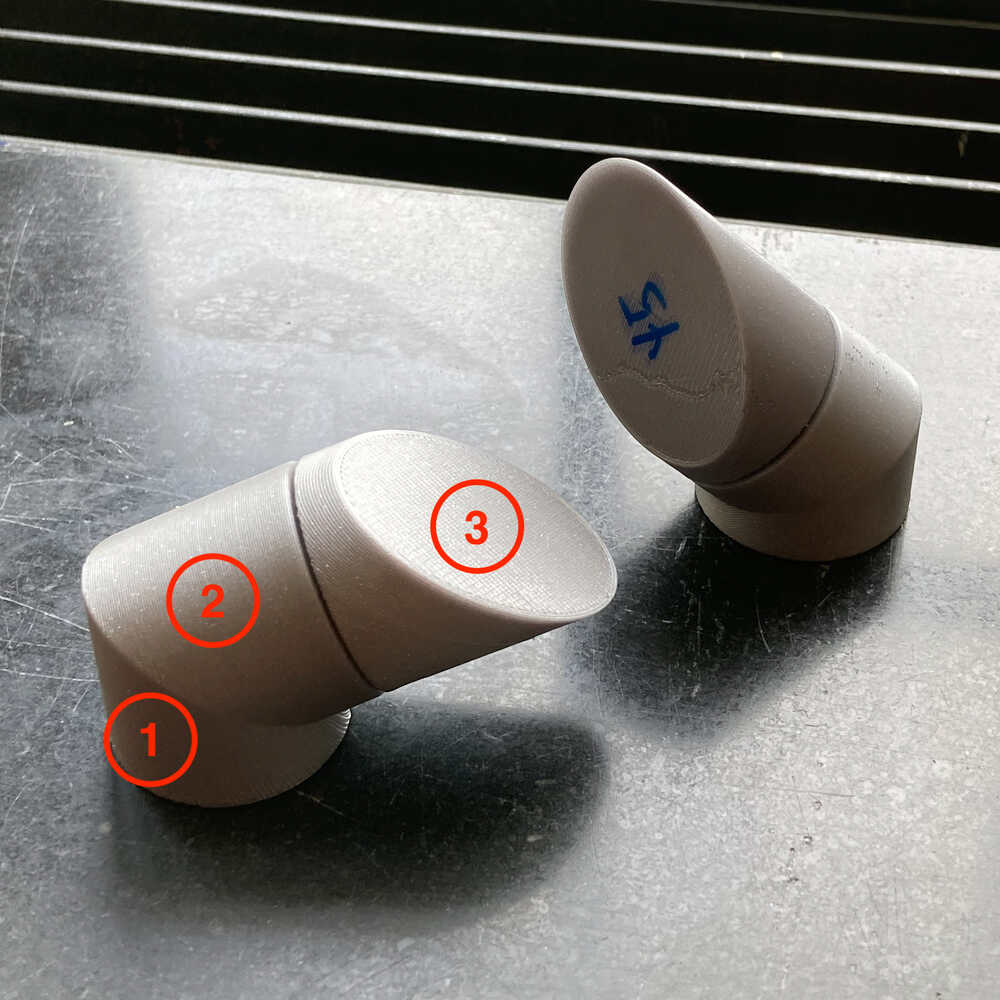
- Controls the heading angle
- Controls the pitch angle
- Mounts on the moving part of 2. and is angled so that movements of 2. actually change pitch
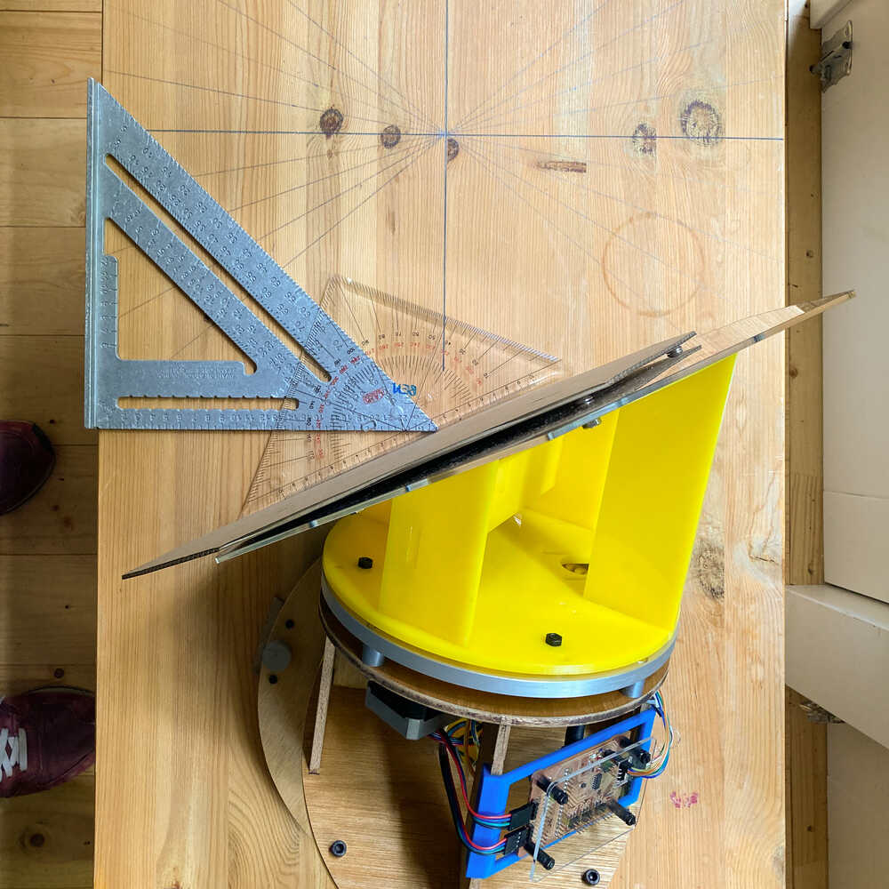
I decided to make 1 and 2 have an angle of 35° so that when they’re combined they point the mirror towards 20° which is the pitch midpoint.
For 3 the angle should be 40° according to my calculations above. I decided to make it 35° so that all 3 parts have the same angle. As a consequence there will be 10° less pitch range but thats fine.
Laser cutting structure 
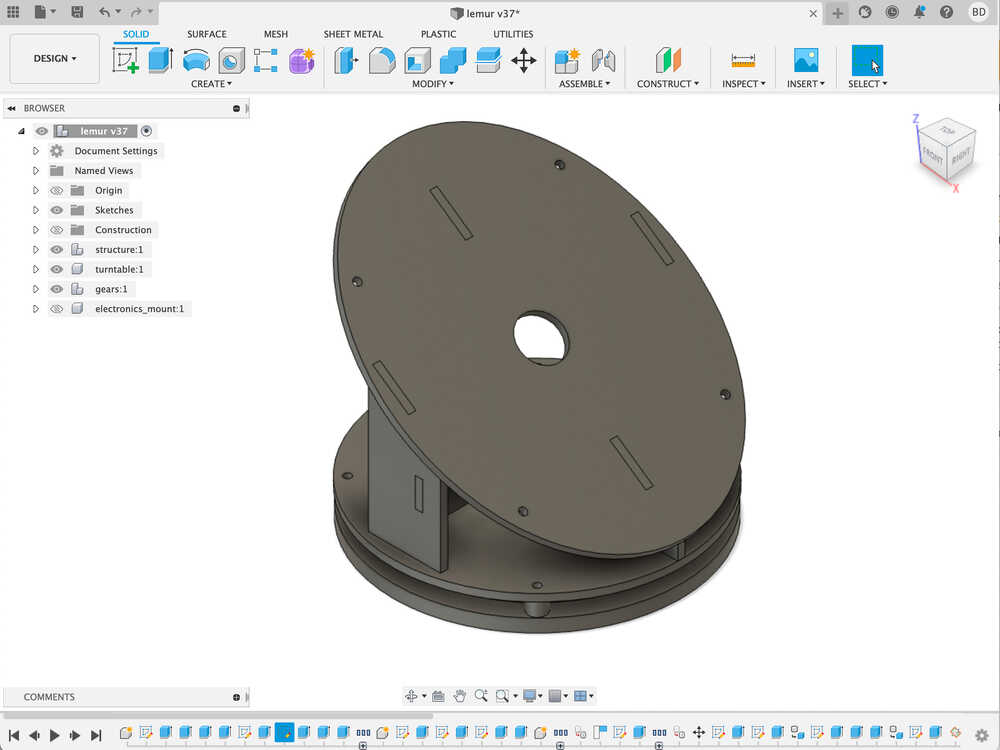
Once I figured out the angles and 3D printed some small prototypes to make sure everything looked right it was time to make a bigger structure. I decided to build the structure out of laser cut parts.
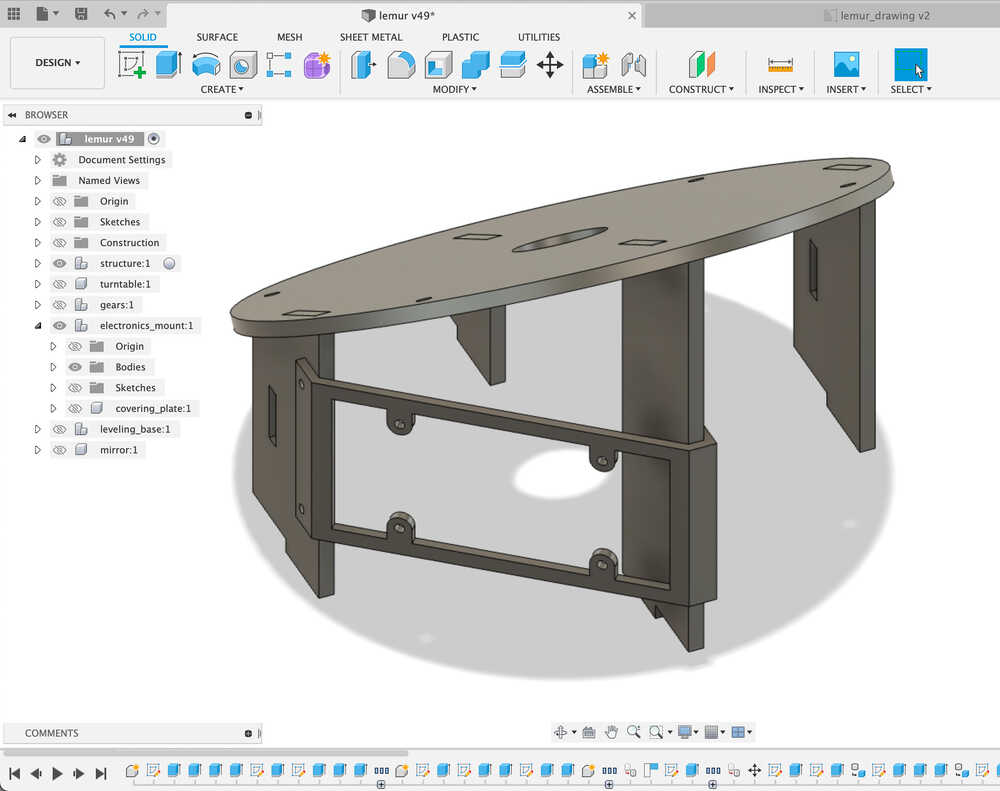
This fusion design shows the structure built from laser cut parts. The assembled heliostat is going to be composed of 3 such components:
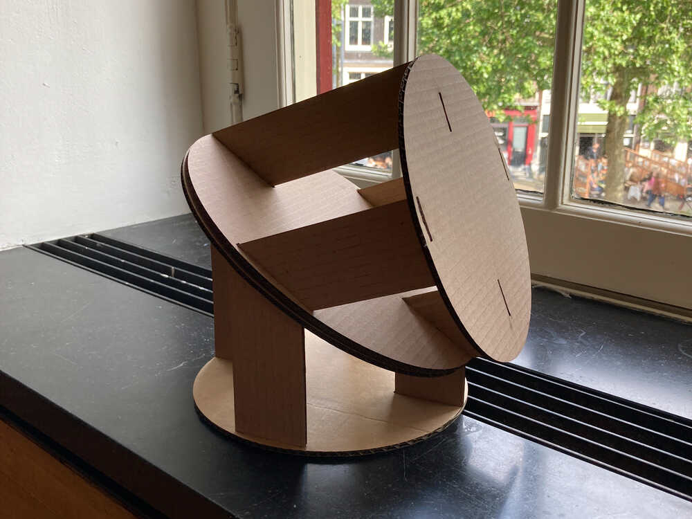
In this cardboard prototype there are 2 parts attached together:
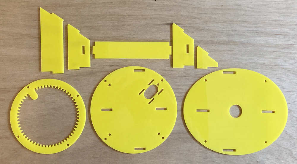
After a few iterations of cardboard prototypes I was happy with the design and I started building units from wood and acrylic. This picture shows the parts necessary to assemble one unit:
Movement
To control the heliostat I’m going to use the motor control board I made in an earlier week.
To connect the moving elements I decided to use this turnable bearing.
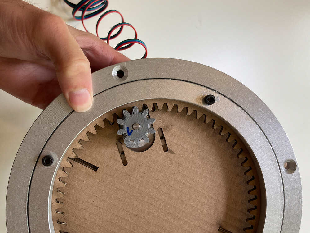
I’m going to move the mechanism with a spur gear that interacts with an internal spur gear ring.
This is the first prototype with a 3D printer spur gear and an internal spur gear ring laser cut from cardboard:
Complete assembly
Once I was happy with the cardboard prototypes I went ahead and made an element from 6mm plywood. I sanded edges of the wood to removed the black burn left by the laser cutter and glued the parts together with wood glue.
I decided to make the second element out of 5mm acrylic to avoid the sanding. We didn’t have any acrylic glue in the lab but it was easy to find in the closest DIY store. I used this hard plastic glue and it worked well.
This video shows a complete assembly doing some test moves:
Electronics mount 
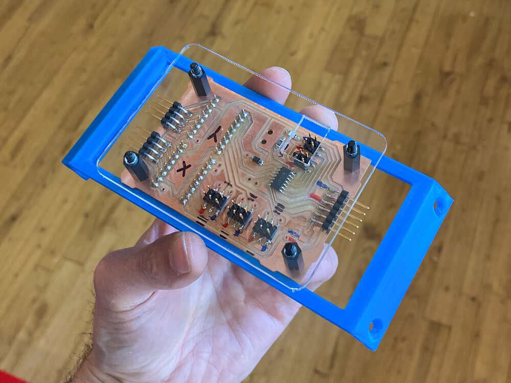
I designed a bracket to mount the motor control board on the structure of the lemur heliostat.
I attached the motor controller board to the 3D printed bracket with M3 screws. To protect the board I added an acrylic plate which is hold in place with PCB standoffs.
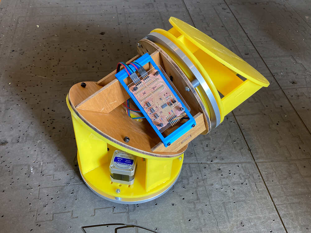
And here it’s mounted on the heliostat structure:
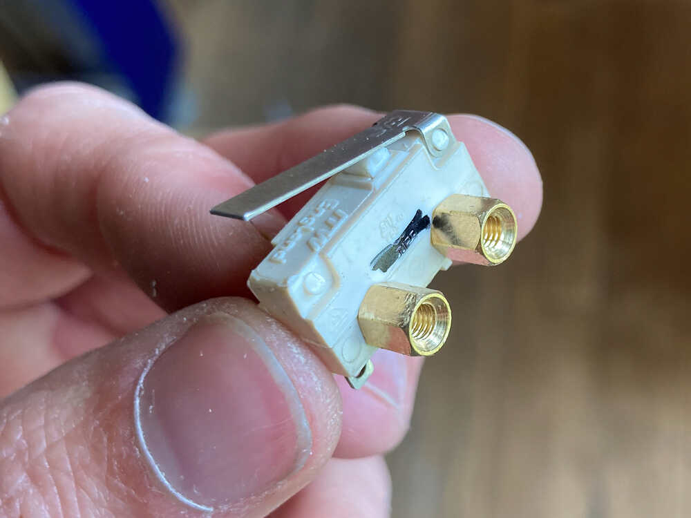
Limit switches
Further up I described multiple approaches to keep track of the mirrors position. As a first step I’m going to home the steppers and keep track of their position. I added limit switches to be able to home the heliostat when it’s started up.
The limit switches have M2.5 holes for mounting. For the limit switches to be in the right position I need them to be elevated by ~5mm from the mounting surface. I did not have M2.5 standoffs but it worked quite well to screw M3 standoffs into the M2.5 holes. That way they kind of self-tapped and removed the need for nuts.
In my design I added a protruding part to ring with inner gear to interact with the limit switch:
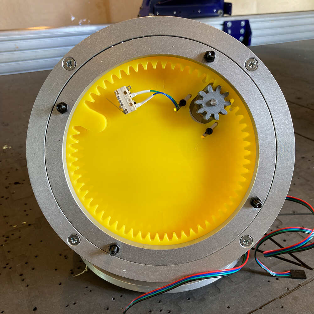
And here homing in action:
Base 
I’m adding a base to the heliostat for 2 purposes:
- The structure is leaning towards one side - without mirror it’s still balanced but when I add the mirror it tips over
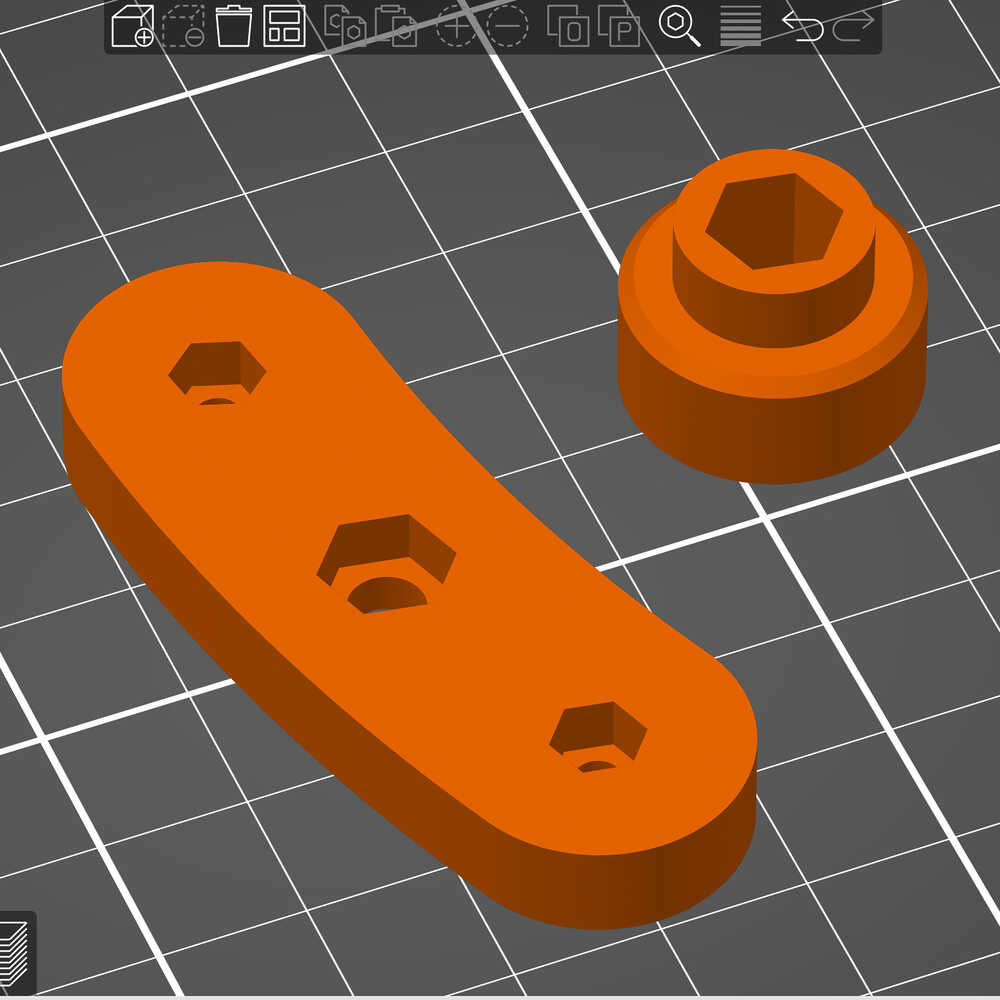
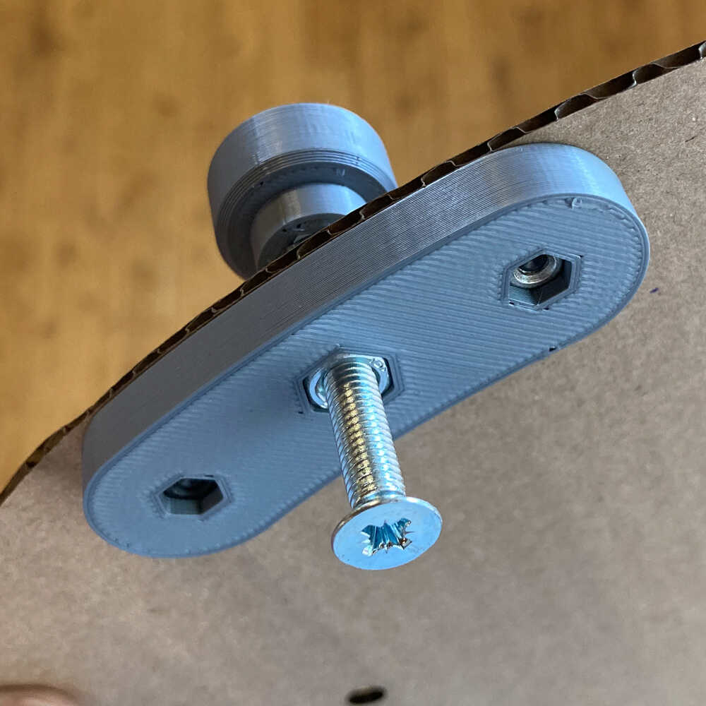
- The heliostat has to be well leveled to work - I will add 3 adjustable feed to the base that allow to adjust the leveling
I designed and printed 2 parts that allow an M5 screw to act as height adjustable foot:
I laser cut the base from 6mm plywood and once everything was assembled I mounted the heliostat on it:
Mirror positioning 
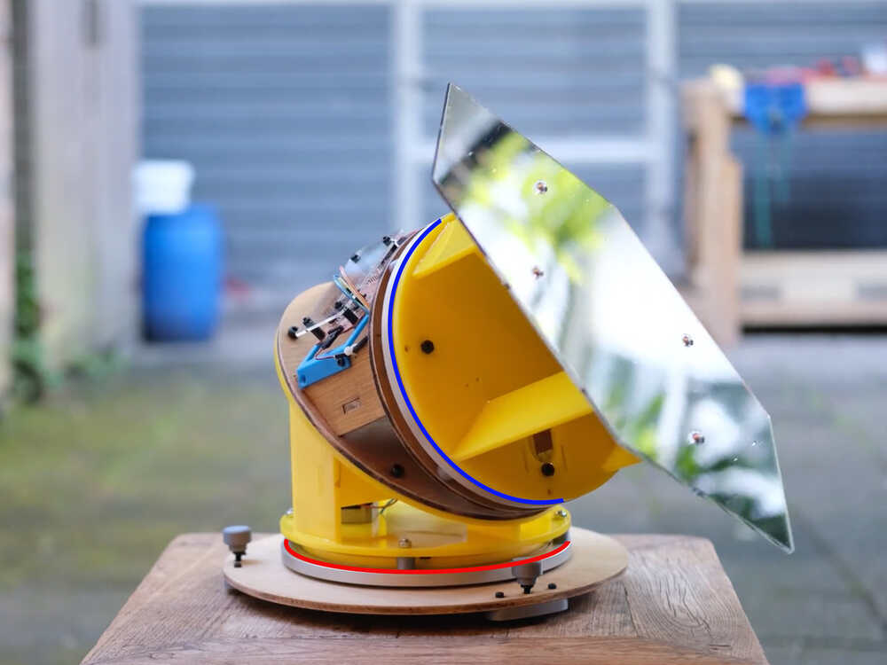
The orientation of the mirror is controlled by rotating the red and blue axis.
- The red axis changes the heading of the mirror - e.g. pointing towards south
- The blue axis changes the pitch (angle between vertical and mirror) and at the same time it changes the heading
I had 2 main challenges to solve:
- How much do I have to rotate the blue axis to reach a certain mirror pitch?
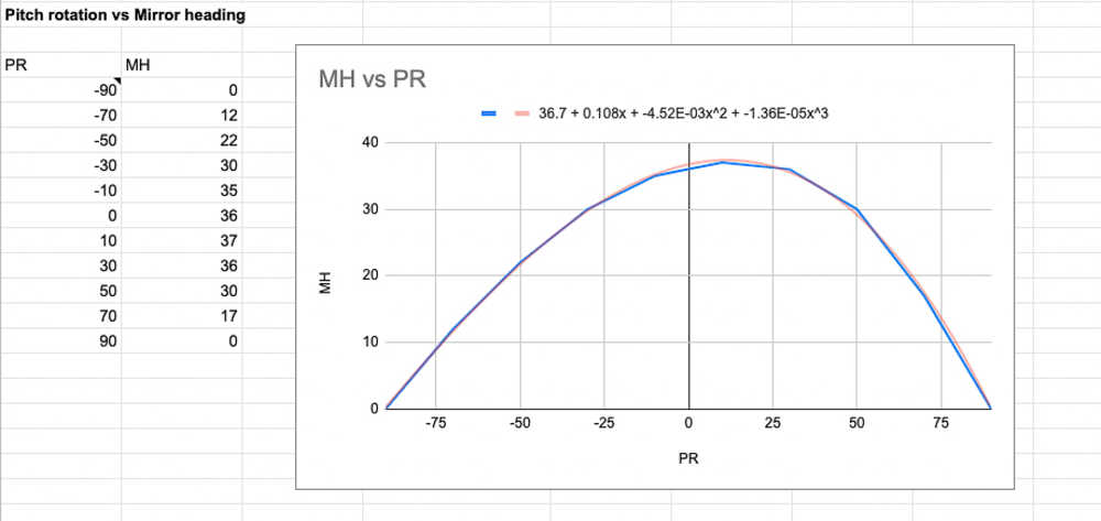
- What effect has the rotation of the blue axis on the heading?
When I designed this heliostat I didn’t think too much about the geometrical relationships and I thought they shouldn’t bee to hard to figure out. When I started to work on the program I realized that I was getting out of my geometry comfort zone. I wasn’t sure how to calculate how rotating the blue axis would impact mirror pitch and heading.
After trying to solve the puzzle from a geometry perspective and failing I decided to take another approach: Measure the relationships in the physical world. I set up the heliostat, adjusted it to be level and then sent commands over serial to rotate the blue axis. I rotated the axis 10° at the time and then measured the effect the rotation was having on the mirror pitch and orientation.
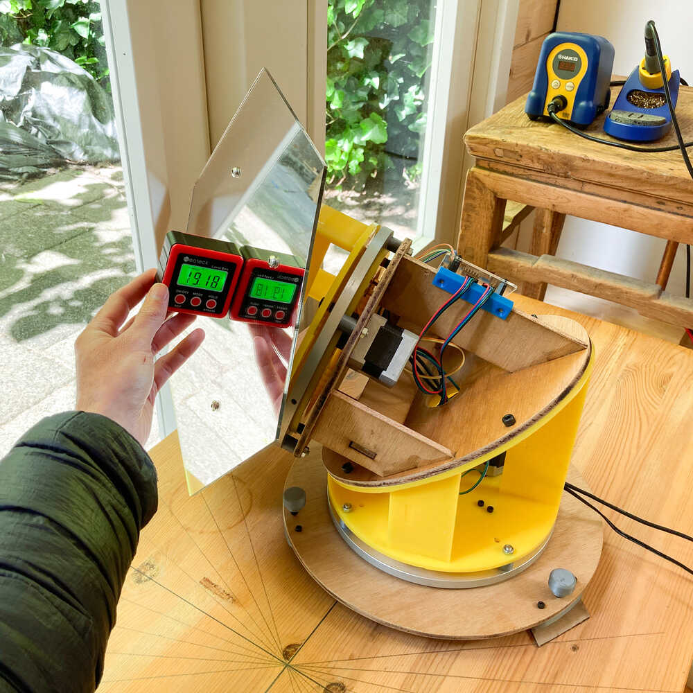
I put all the measurements in a google sheet and created a graph from them
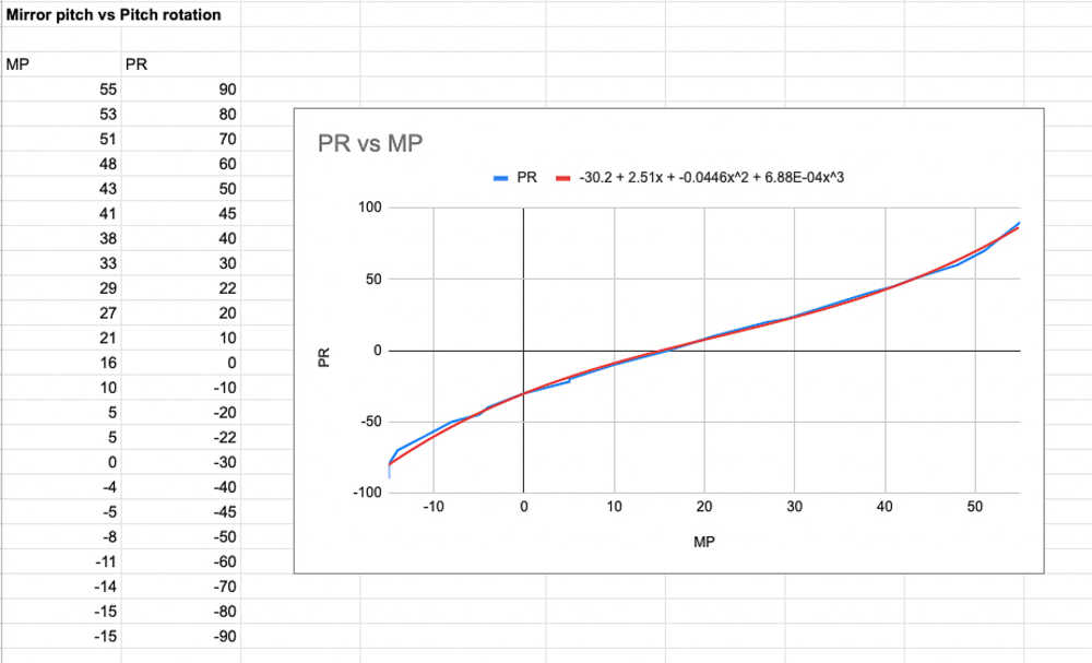
Now I have a nice graph but how do I bring that knowledge into my program?
Google sheets have the handy feature to create multiple types of trend lines. A trend line is a function that approximates the points on my graph. I opted for polynomial functions of 3d degree as they approximated my measurements quite well. In the graphs above you can see the measurements in blue and the trend lines in red.
To enable trend lines: Double click graph > Customize > Series > Check 'Trend line' > choose type > Label: Use equation
By choosing Label: Use equation, the function is shown in the graph. I copied the function from the graph and used it in my program.
This method is not perfect as it is an approximation. For now I will use this functions and focus on other tasks to complete the heliostat. If I have some time left later I’d like to come back to this puzzle and understand the relationships from a geometrical perspective.
Now I’m able to send commands to the motor controlled board telling it to position the mirror at a certain pitch/heading and the microcontroller takes care of performing the necessary rotations to position the mirror.
Interactive fusion design
The heliostat consists of 3 equal components. This design shows one component with electronics mount, mirror and base.
Cockpit application
Last week I wrote the program that runs on the motor control board microcontroller. That program receives commands telling it where to orient the mirror and then it takes care of rotating the motors to reach that orientation.
This week I’m going to write a second program that takes care of figuring out where the mirror should be oriented based on the sun position and the place where we want to reflect to. This program is going to run on my computer and will have a user interface - I’ll call it Lemur Cockpit
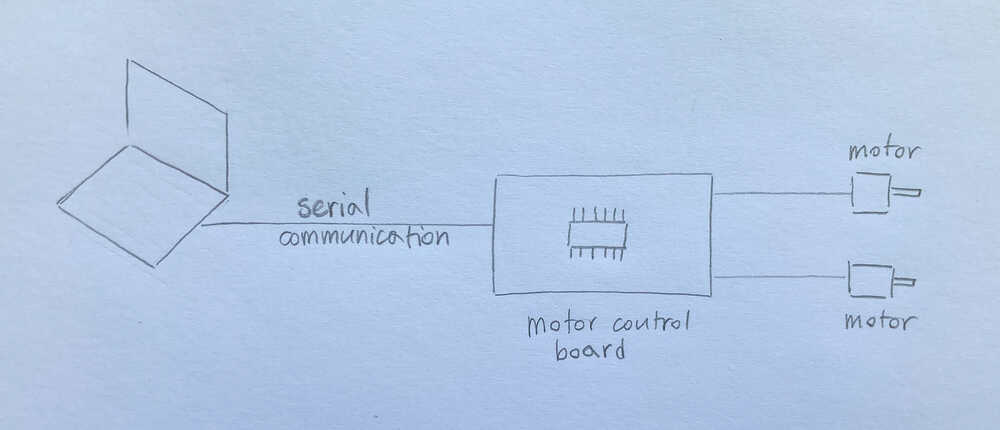
I made a web application that communicates with the motor control board using the Web Serial API as I enjoyed working with this setup in an earlier week
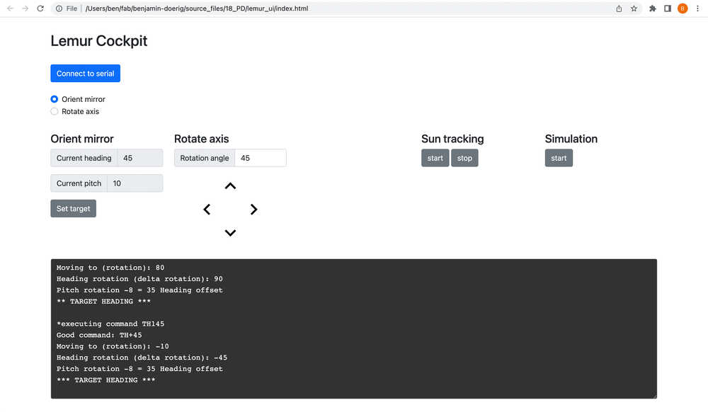
Using the lemur cockpit I can:
- Orient the mirror at a certain heading and pitch
- Rotate heading and pitch axes by X degrees
- Set target where sun should be reflected to
- Start / Stop automatic sun tracking
- Run simulation
- See logs from the motor control board
When the automatic tracking is activated the program continuously adjusts the mirror orientation to continue reflecting to the same place even when the sun moves. Further up I described multiple approaches to know where the sun is. Initially I was thinking of calling an API but it turns out that there is a javascript library to calculate the sun’s position - that’s even easier :-)
Testing & simulation
Last week I did measure the pitch and heading of the mirror to verify that the program was doing what I expected. The pitch is easy to measure with a digital inclinometer but I didn’t find any way to easily and accurately measure the heading. I can use a digital protractor but I still need to manually align it with the mirror which isn’t so easy depending on the mirror orientation.
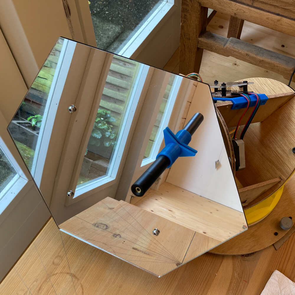
I decided to get a laser pointer and mount it on the mirror. That way I can make measurements using the laser dot which is projected on the wall.

I did run some simulations to see how the heliostat adjusts to the moving sun. In the simulations I set a target where the heliostat should reflect to and then I let time pass by and observe how the heliostat adjusts to the sun’s movement.
In this simulations there is no real sun - that means that I can not verify the reflection but I can still see how the mirror adjusts the place where it’s pointing to over time. To avoid having to wait an entire day for a simulation to run I speed up time. In this video I simulate the sun’s movement between 11:30 and 18:30 in ~10 min.
Note how the laser point on the wall makes it easy to see where the mirror is pointing to: