14. Interface and application programming
Planning
Tasks - Must
- Group: Compare as many tool options as possible
- Write an application that interfaces a user with an input and/or output device that you made
Tasks - Nice to
- Make a motor driver board for my final project
Execution
Processing 
Bas gave us a good introduction to Processing. I’ve never used processing before but it feels like an easy-to-use environment.
Processing 4
At first I downloaded 4.0 beta 8. It worked for some simple drawing examples but I wasn’t able to get the serial examples to work. When running the SimpleRead example I got the following error:
UnsatisfiedLinkError: Could not load the jssc library: Couldn't load library library jssc
A library used by this sketch relies on native code that is not available.
Once I downloaded the previous version (3.5.4) everything worked fine
I wrote a program that draws a circle whose diameter is controlled by a value received via serial. The value controlling the circle is a phototransistor reading coming from my hello world board.
Web Serial 
Next I tried the Web Serial API as it sounds pretty cool to be able to access the serial port directly form the browser.
Browser support
Be aware that not all browsers support the Web Serial API. I used Google Chrome for my experiments.
I made a simple website that changes the background color based on the value received via serial:
WebSocket 
Bente gave an introduction to the WebSocket API. I wasn’t able to attend her lesson but the presentation and the examples she shared helped me to get started.
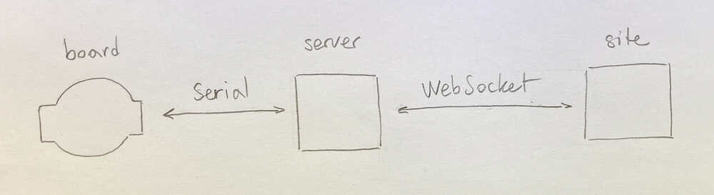
I created an example with 3 components:
- Arduino sketch running on
boardthat communicates withservervia Serial. The board outputs the phototransistor reading and turns the LED on/off based on the input it receives - Node
serveracting as a Serial to WebSocket bridge sitethat communicates withservervia WebSocket. The site shows a circle that adjusts it’s dimension based on the phototransistor reading. When the circle is clicked it changes color and a command is sent to the board to turn the LED on/off
Motor control board 
I want to make a board with a microcontroller and 2 motor drivers that I can use to control the stepper motors of my final project.
I started designing a board using the TMC2100 motor drivers we have at the lab. While working on the schematic I started wondering If it was even possible to mill a board using these motor drivers as their pins are really close to each other (lead pitch 0.5mm).
Given the 0.5mm lead pitch and the 0.4mm mill I would have to use 0.1mm traces. I modified the TMC2100 footprint to have 0.1mm wide pads and then made a test board containing only that footprint to see if it is millable.
0.1mm traces
In mods it looked all right but the tiny pads detached from the board. I made a second attempt where I added traces to the pads to make the 0.1mm copper strip longer. This time the trace did partially stick to the board but it was still a failure.
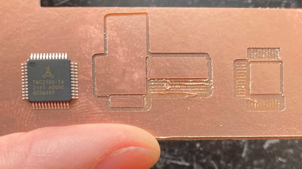
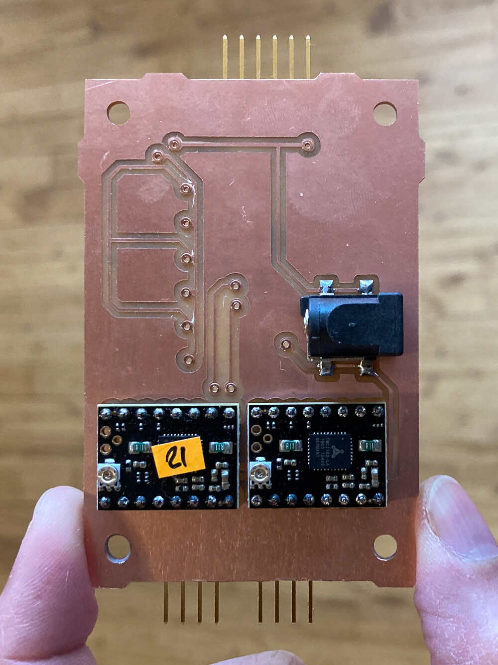
As I’m not able to use the TMC100 drivers directly I’m going to use the SilentStepStick breakout board containing the same drivers.
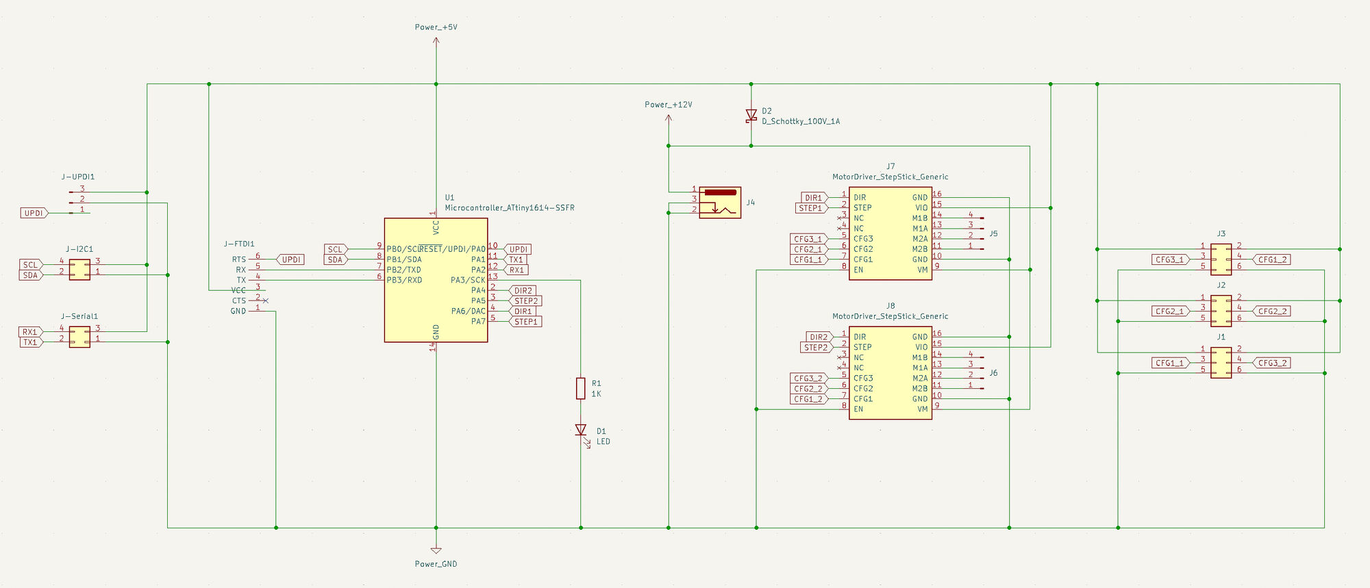
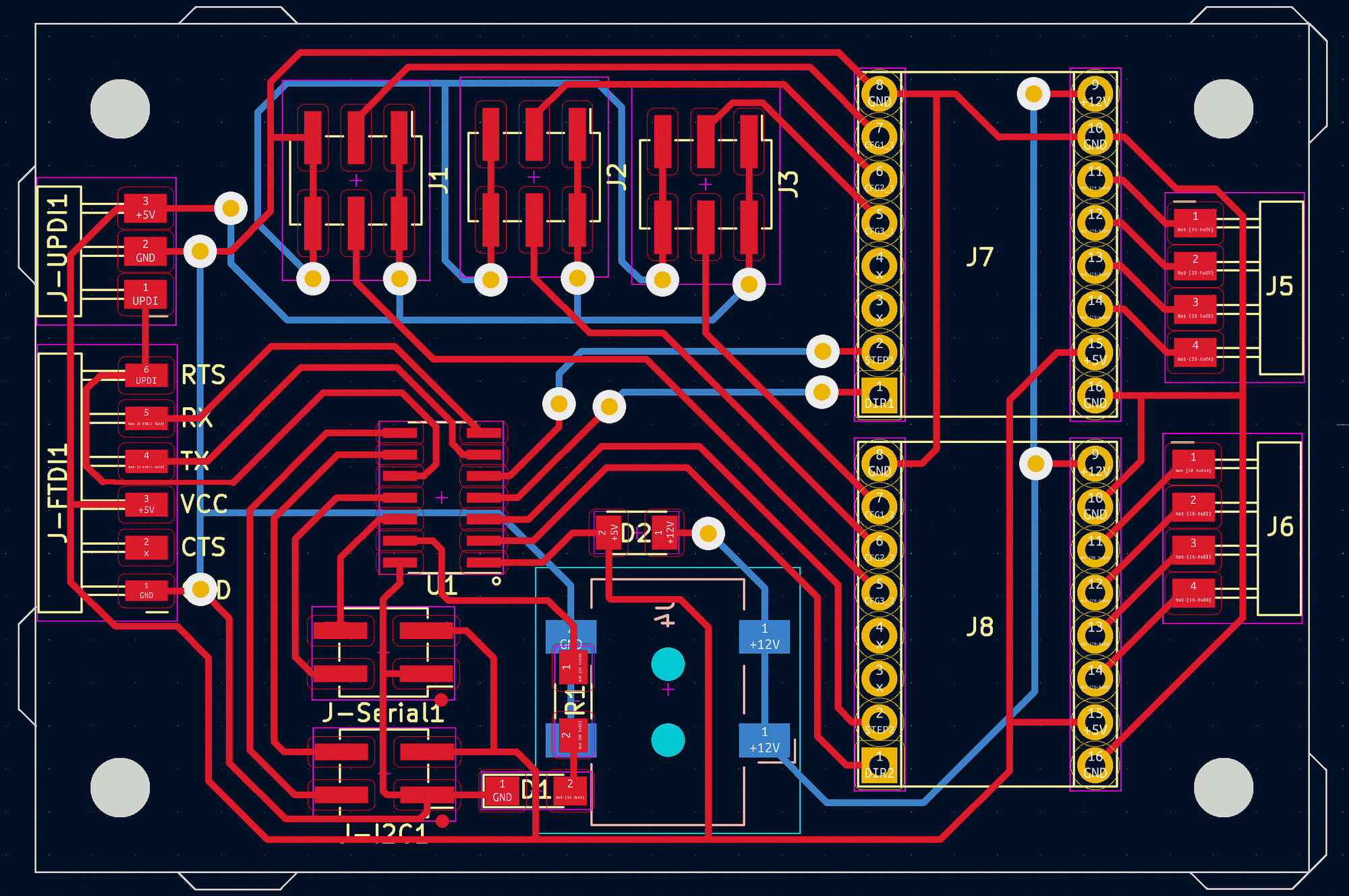
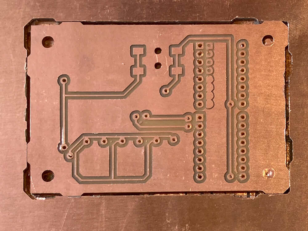
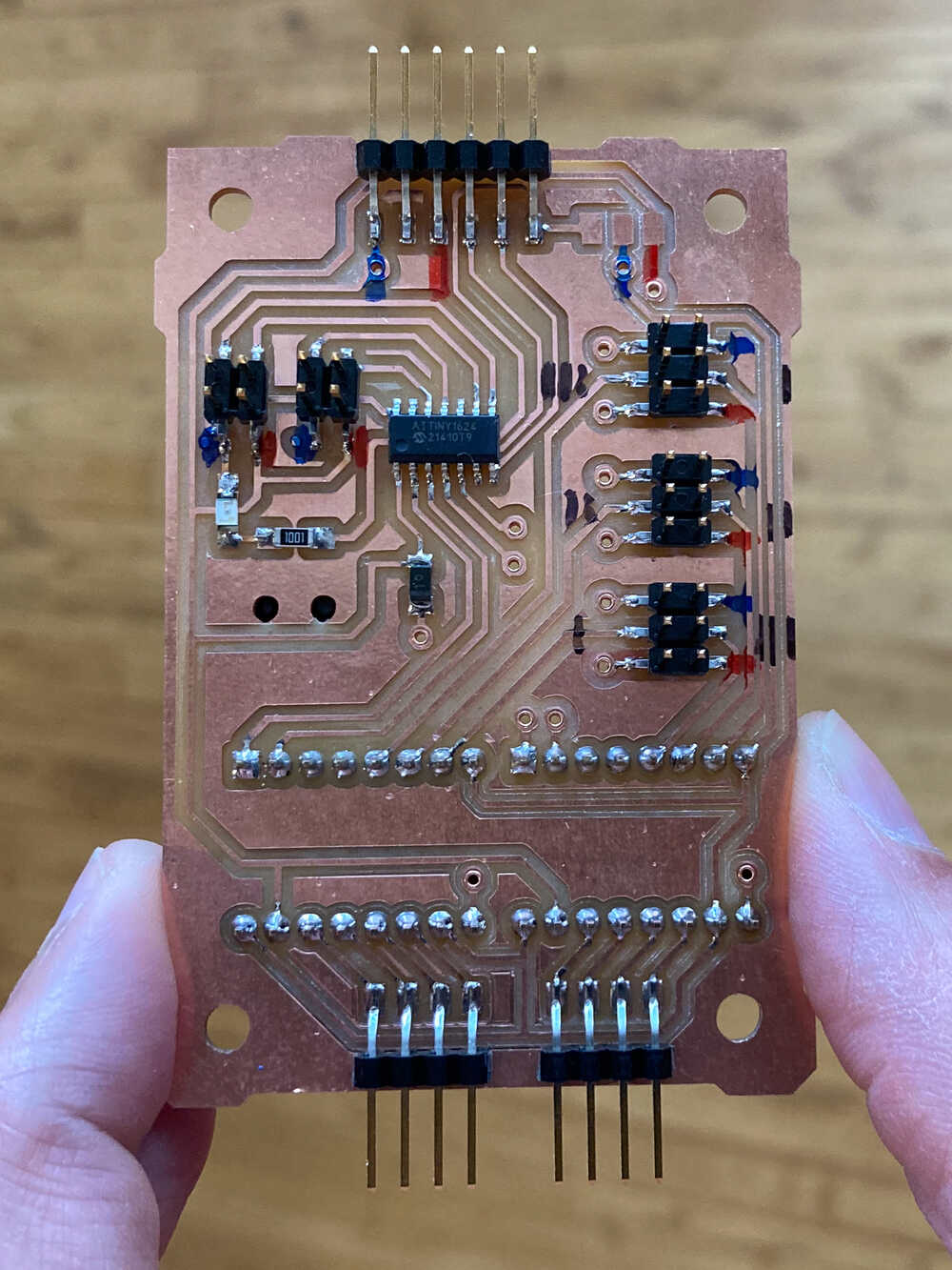
When I started working on the PCB I realized that it’s going to be quite tricky to route everything on one layer. Instead of using many zero ohm resistor bridges I decided this was a good opportunity to make my first double-sided board.
I took a look at Douwe’s documentation to see how he did a double-sided board during last year’s Fab Academy.
Registration tabs
I included registration tabs in the outline of the board so that I can put the board back in exactly the same position once I flip it over. The tabs are as wide as the milling bit used for the outline (1mm) to compensate for the material which is removed by the milling bit. This approach worked well :-)
Board orientation
I designed my board oriented horizontally. When I was setting up the milling machine I realized that it would make more sense to have the board vertically to use the FR1 board more efficiently. I simply rotated all the images used for production with imagemagick:
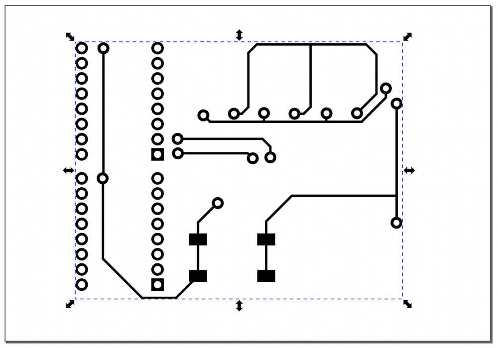
bottom traces flipping
As I’m flipping the board over to mill the bottom traces, I have to flip the bottom traces image over too so that it matches the top layer.
 In inkscape I flipped the selected traces. This did lead to a wrong result as this did flip only the selected part instead of the entire image.
Once I realized the inkscape flipping was wrong I used imagemagick to flip the entire image and that worked
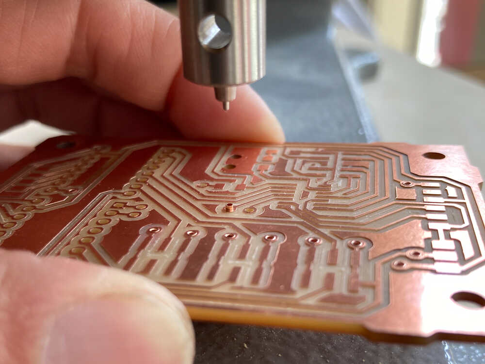
Hole drilling depth
Some of the holes were not completely drilled through.
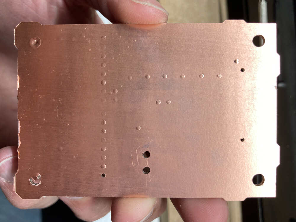
It was just the bottom copper layer which was not drilled through. I punched through the copper layer using the 1mm mill by hand.
Once I completed the milling it was time to press the rivets acting as vias in place:
Once the vias were in place I stuffed the board the same way as I would with a one-layer one. This is the finished board and it works :-)
Orientation sensor test setup 
Last week I experimented with the BNO055 absolute orientation sensor.
To understand how accurate the sensor is I did put it manually at a certain angle and then checked the measurement. To really understand how accurate the sensor it I’d have to do many such measurements. Making hundreds of manual measurements is boring and error prone so I decided to make an automated setup.
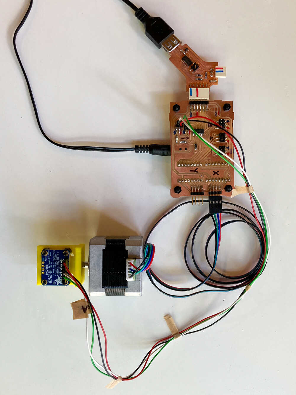
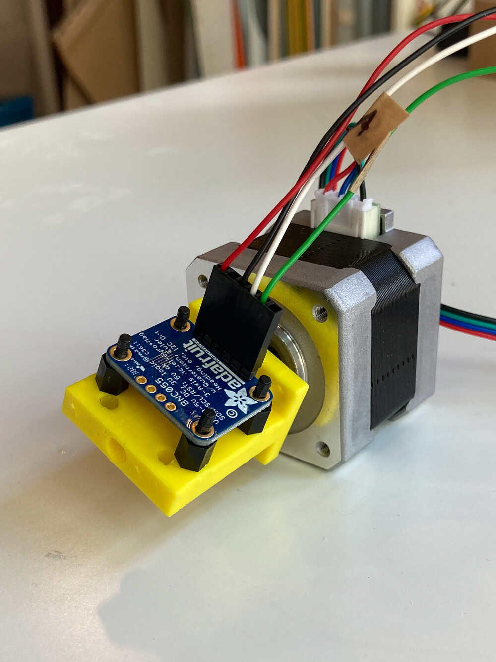
I designed a bracket to mount the orientation sensor to the shaft of a stepper motor. With this setup I can rotate the stepper to a known angle, read the sensor and compare the two angles.
I was planning to create an interface that shows a graph that visualized the real and the measured angle. I didn’t get to that point yet. So far the graph is showing only the angle measured by the orientation sensor.
Retrospective
I was surprised by how few lines of code it requires to get an application running on my computer to access serial communication. Especially with Processing and WebSerial it was really easy to create a simple example.
This week I spent quite some time to design and produce the double-sided motor control board. It was well spent time as I learned a lot and it’s a useful skill for creating more complex boards.
I really like the idea of the automated orientation sensor test. It’s a shame I didn’t have enough time to complete it but I could well imagine to pick this up again. It would be really useful to be able to make hundreds of orientation measurements to understand how accurate the sensor actually is.