5. 3D Scanning and Printing
Planning
Tasks - Must
- Group assignment: Test the design rules for your 3D printer(s)
- Design and 3D print an object that could not be easily made subtractively
- 3D scan an object
Tasks - Nice to
- Print hinges
- Experiment with vase mode
- Make a “transparent” print
- Try non planar 3d printing
- Make a self adjusting heliostat
Execution
Group assignment
We worked in 3 groups. Each group tested one of the 3D printers. I worked together with Bas and we tried out the Creality Ender 3 printer.
Henk told as from the beginning that this printer was going to be tricky to work on as the hotend fan is damaged and Michelle was trying to get the printer to work reliably recently but she didn’t succeed yet.
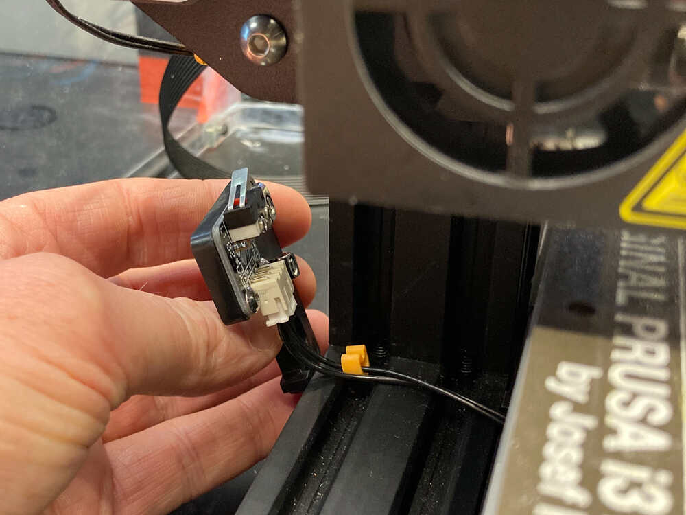
Damaged hotend fan
Some of the blades of the hotend fan are broken. It should still work for cooling but because of the broken blades it makes the fan and all the parts around it vibrate. A replacement hotend fan was already ordered but it didn’t arrive yet.
Z zero
When we turned on the printer it started homing. When it was moving to the end switch of the Z axis we noticed that the nozzle was pushing on the heat bed.
Loose Z axis end switch
When Bas touched the Z axis end switch it fell off the frame. Maybe the vibrations from the fan loosened its screws. We put it back in place and tightened the screws.
Bed leveling
This printer does not have auto bed leveling. We checked if the bed was level by:
- Moving Z slightly above zero (10mm) in the menu (to avoid scratching with nozzle on bed while moving)
- Move hotend to one corner of the bed by adjusting X and Y in the menu
- Move Z to zero
- Check distance between nozzle and bed. We adjusted the bed up/down with the adjustment screws until a piece of paper fits between nozzle and bed but there is a bit of resistance when moving it.
- Move Z back up (10mm)
- Repeat for every corner
Bed leveling screw moving with vibration
One of the bed leveling screws was moving by itself due to the vibrations of the damaged fan. As a quick fix we taped it in place to stop it from rotating.
First layer calibration
Bas designed a model in openscad and sliced it in cura. This was simply printing 4 circles, one in each corner of the bed.
Underextrusion
When we started the print we noticed that the printer was extruding less filament than expected. We made a mark on the filament and then manually got the printer to extrude 50 mm. Using the mark we were able to measure that only ~25mm of filament were extruded. We adjusted the steps/mm setting for the extruder and repeated the test again. After a couple of iterations the printer was extruding the right amount of filament.
We started the print again and while it was running we fine tuned the bed up/down until the squares were printing nicely
Print test model
As a next step we downloaded this model, sliced it and started printing it.
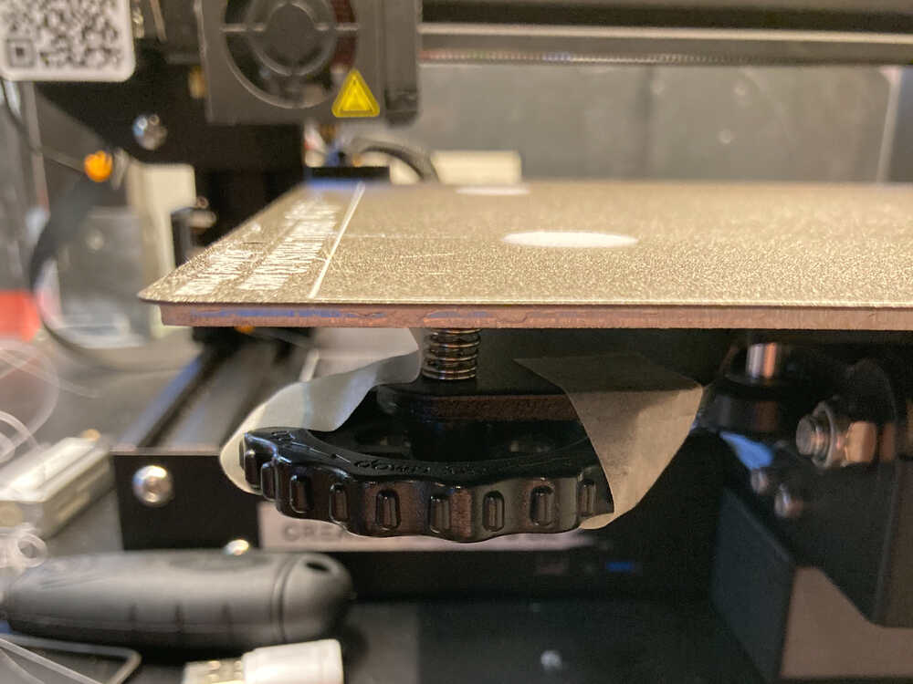
Bed not flat
The model was not printing properly because the distance between the nozzle and the bed was too big. How is that possible? We just adjusted that. After checking again a corner we realized that the bed had a slight bowl shape instead of being flat (corners higher up than center). That’s why the nozzle was at the right height in the corners but too far from the bed in the center.
Bed leveling & first layer calibration for bed center
As the bed is not flat we decided to calibrate the printer so that it would print correctly in the center area of the bed.
To do so we repeated the bed leveling and the first layer calibration we did earlier just that this time we did it in the center area of the bed instead of the outer corners.
 Here we switched to a different test file that prints squares instead of the circles we initially used.
Print test model… again
We started the test model print again and this time the nozzle/bed distance looked a lot better but the filament did still not stick to the bed properly everywhere. We had the same result after cleaning the bed with glass cleaner.
Conclusion
After spending multiple hours tweaking the printer and still not getting it to fully work we decided to stop. At this point it makes more sense to wait for the replacement fan to arrive before spending more time on the printer.
The printer uses a prusa textured steel sheet. This sheet is not ideal for PLA bed adhesion but it should still work if the first layer is calibrated well and the sheet is clean. Flexible beds are super practical to take prints off but as they are meant to be bent they will never be perfectly flat. I’d say it’s not ideal to use a flexible bed on a printer without mesh bed leveling.
We didn’t manage to get the test model to print on this printer. I assume it was a combination of vibrations from the fan, bent bed, sheet texture not ideal for PLA adhesion and not perfectly tuned first layer that did lead to this.
Continue with prusa MINI
As we didn’t get the Ender 3 to work at the Waag I’m continuing the exercise at home. After the slightly frustrating experience tweaking the Ender I appreciate my own printer even more :-)
From here on I’ll be using a Prusa MINI+ with 0.6 mm nozzle.
I started by printing this test model:
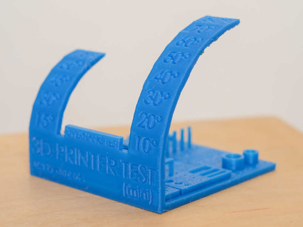
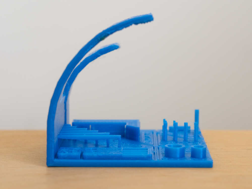
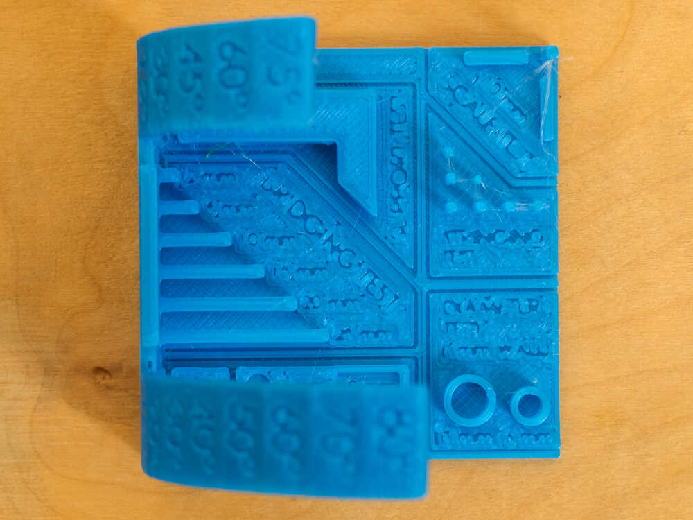
In the test print I see:
Overhangs:They’re perfect up to45 degreeand acceptable up to60 degreesBridges:The20 mmbridge looks good but even the25 mmone is acceptableStringing: There is a bit of stringing between the stringing test posts. Possibly that’s because I’m using a rather old filamentOuter diameters: Both diameters are~0.1 mmtoo bigInner diameters: Both diameters are~0.2 mmtoo smallScale: X, Y and Z features are all accurate (~0.05 mmtoo big)Holes: The width of the squares is accurate (~0.05 mmtoo small). The height of the squares and diameter of the round holes have different accuracies (0 - 0.4 mmtoo small). The smaller the feature the less accurate it’s measurement isSupports: I’m not sure how to interpret the support test on this model
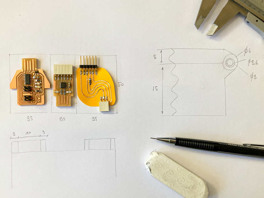
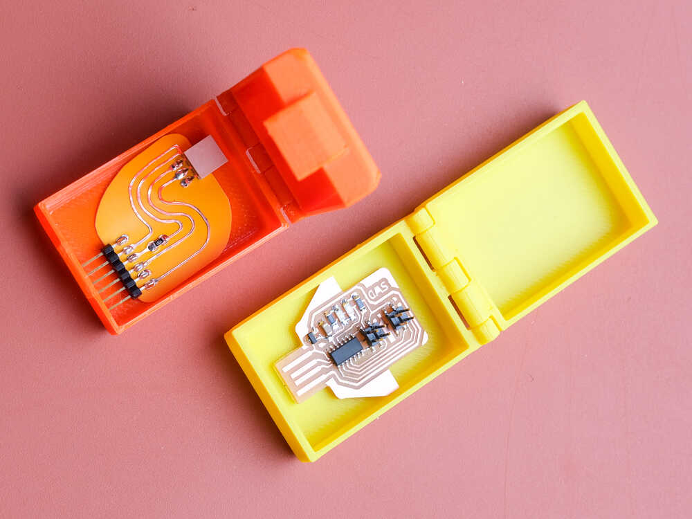
Box for programmers 
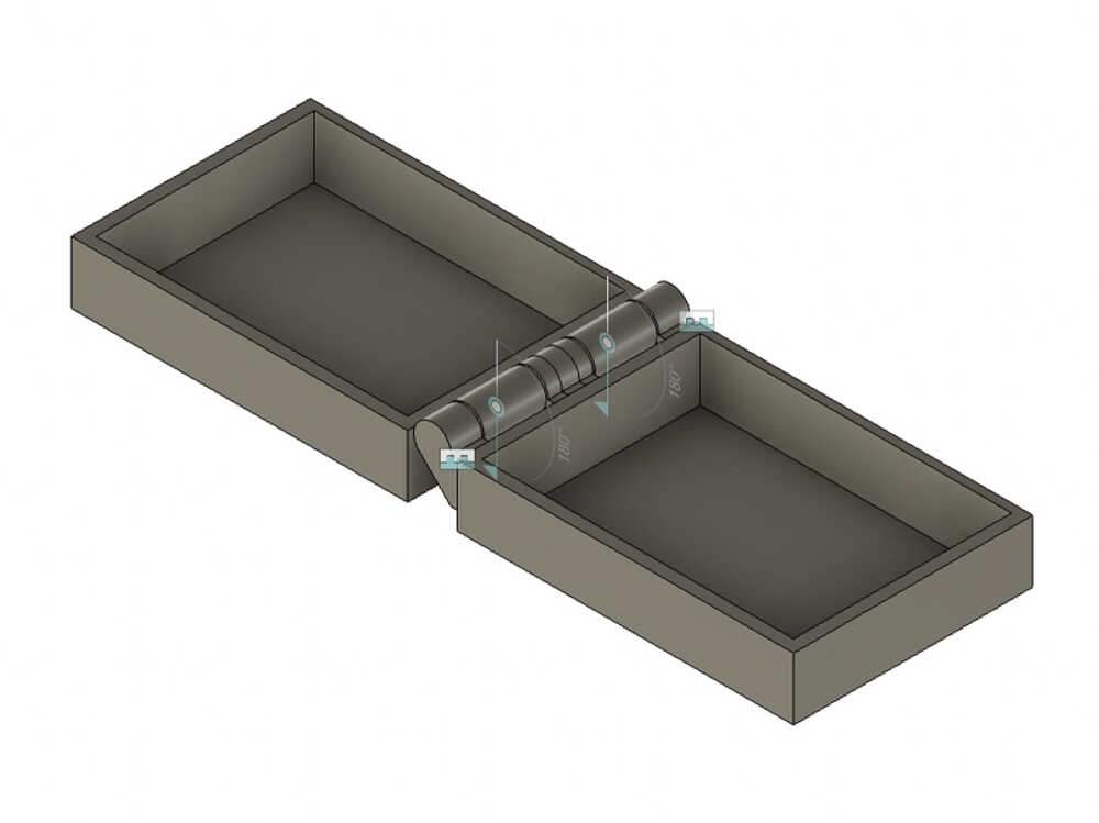
I want to model and print a box that fits the PCB’s I produced last week. My goal is to come up with a model that can be printer without supports and I want the box including hinges to print in one go.
1st prototype
I started with some sketching on paper to come up with some dimensions and a first idea on how the box could look. Once I had a rough idea I started modeling the box in fusion 360.
Instead of creating a full sized box straight away I started by designing a smaller box that could be printer more quickly. Faster prints will allow me to iterate more quickly.
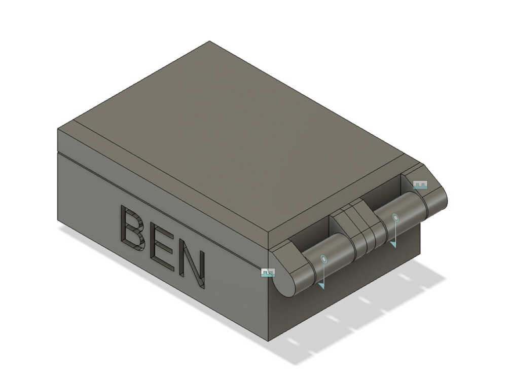
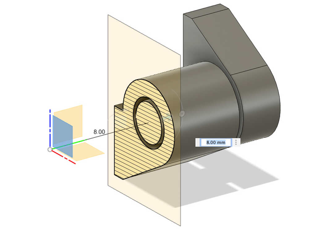
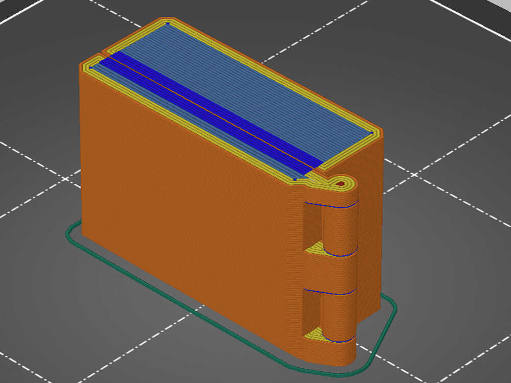
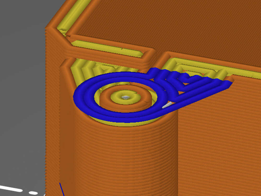
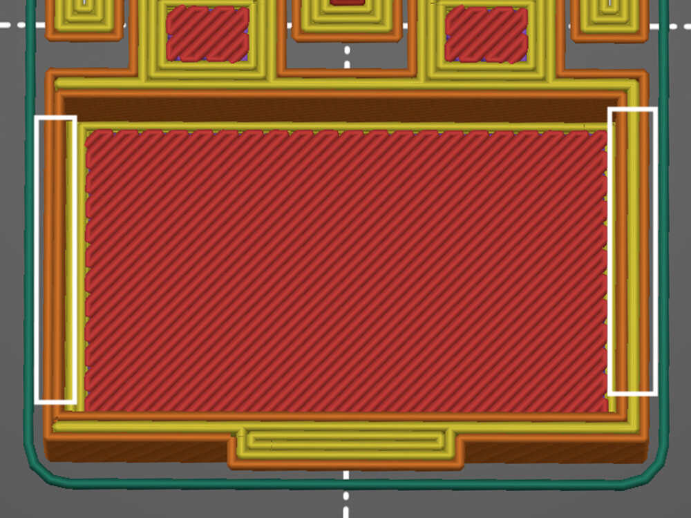
My first idea was to print the box laying on it’s side but when slicing (in prusa slicer) I realized that this position might not be ideal:
- There are long bridges to print the side of the box facing upwards (blue part in first image)
- In the hinges there sections with big overhangs (blue part in second picture)
Slicing parameters:
- Preset: I started with the
0.2 mm DETAILprofile and slightly tweaked it - Perimeters: Adjusted to
4(default2) to make the hinges stronger - Infill:
20%This doesn’t really matter as the box mostly consists of perimeters. Only a tiny part of the hinges has infill
I decide to still go ahead and make a test print. I assume the overhangs in the hinges will just “sink” on the layers below with which in theory they should not be in contact but it might still be possible to break them apart and make the hinge move once the print is complete. For the long bridges they will probably not turn out great but I was curious how bad it wold be.
Long bridges and hinge overhang
The critical parts turned out worse than I expected:
- It required quite some force to open the box and when I opened it the hinges partially broke
- The surface below the long bridges is not acceptable
- There is quite a bit of stringing inside the lid: Not 100% sure why but it might be because I’m using a filament which is quite old
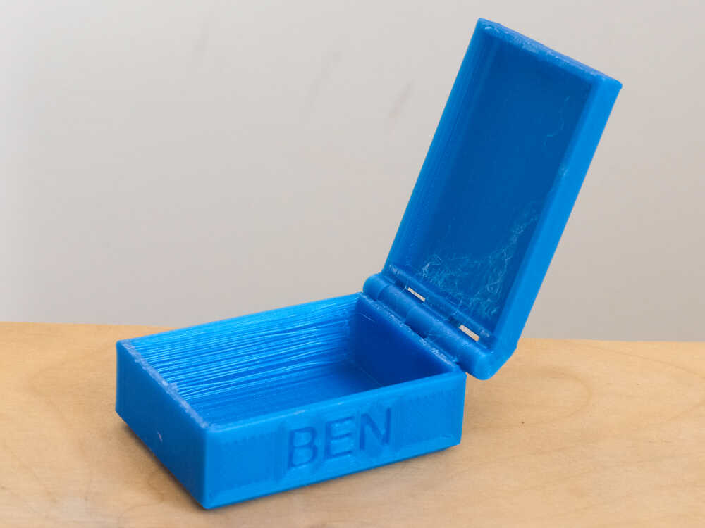
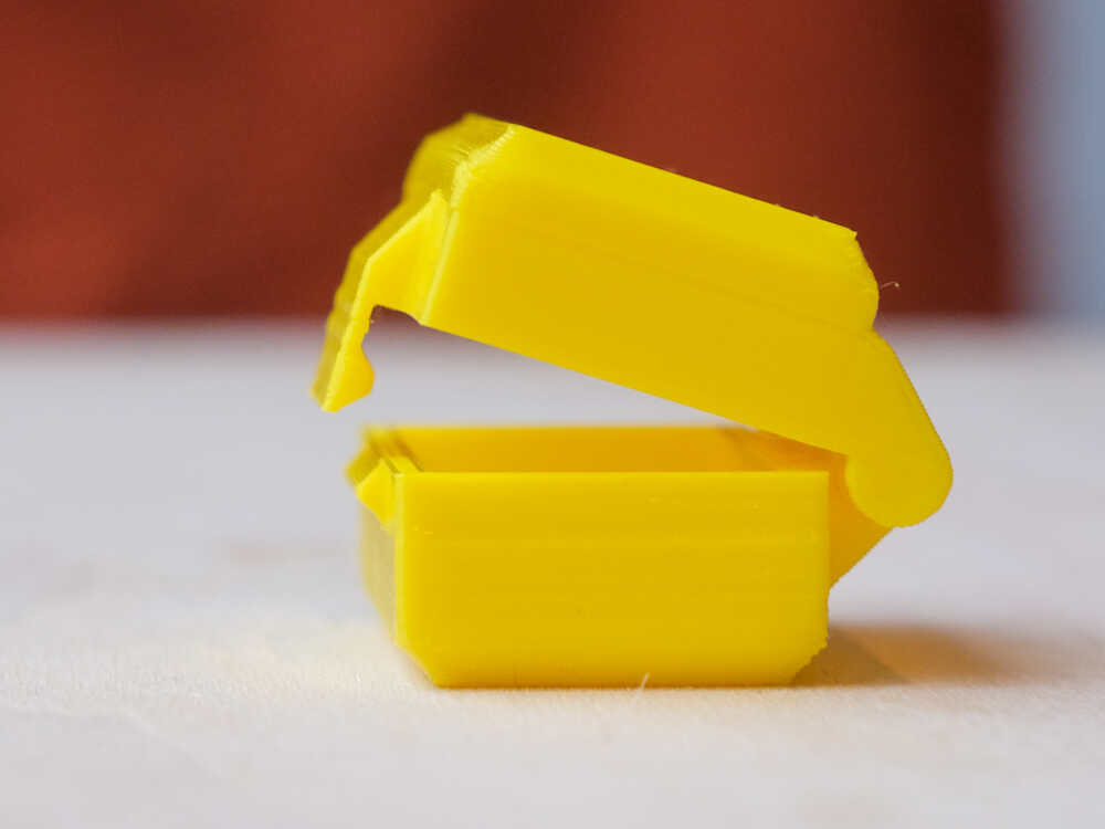
2d prototype
Next I decided to change the design an make lid and box body the same size. This will allow me to print the box laying flat and open.
This turned out much better :-) After applying a bit of force back and forth I managed to get the hinges loose without breaking them. This time I used a newer filament and that solved the stringing problem.
Keep the box closed
I happy with the box and the hinges but I want to add a feature that keeps the box from opening by itself. I will add a tongue on the lid that snaps into a feature on the box body.
The snap closure works but the tongue feels quite stiff. I don’t think that it will take long before this mechanism breaks. PLA is quite brittle and doesn’t like to be bent. The extrusion orientation on the tongue isn’t ideal either: The tongue would be stronger if the extrusion lines would be vertical instead of horizontal but it’s not possible to print it that way as we saw earlier that the hinges can not be printed upright. I will print the next box in PETG: that should make the tongue more flexible.
Inconsistent wall thickness
When I checked the printed part I realized that the side walls don’t all have the same thickness. A look at the slicer confirmed it. I checked the fusion drawing and I did indeed forget a constraint.
As I was already thinking about wall thicknesses I decided to make them a bit thinner so that they consist of 2 extrusions. Until now I specified walls to be 2mm and now I change them to be 1.3mm (2 * 0.65 which is my default extrusion width). This will make the print faster, uses less material and I think the box will still be sturdy enough.
I printed a PETG version with the new wall thickness and the new design works.
Moist filament and overhangs
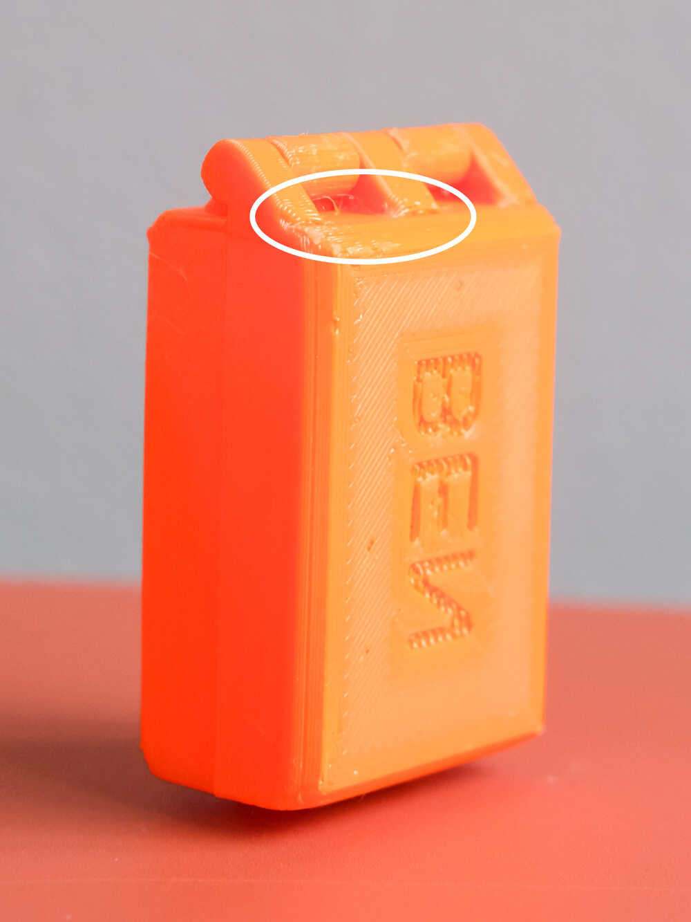
The print quality wasn’t great on this box. While it was printing I noticed that once in a while there was a little “pop” as if a bit of air was coming out of the nozzle instead of filament. After a bit of googling I came to the conclusion that probably my PETG filament is a bit moist and that pop is evaporating water. When I took a closer look at my dry box I saw that some of the silica bags started to turn green (A sign that they’re saturated). I’ll go ahead and dry out the silica bags in the microwave.
I did as well notice that where the hinges meet the box the print is not really good. I checked the fusion model and there is a little overhang there. I’ll adjust the model to avoid the overhang.
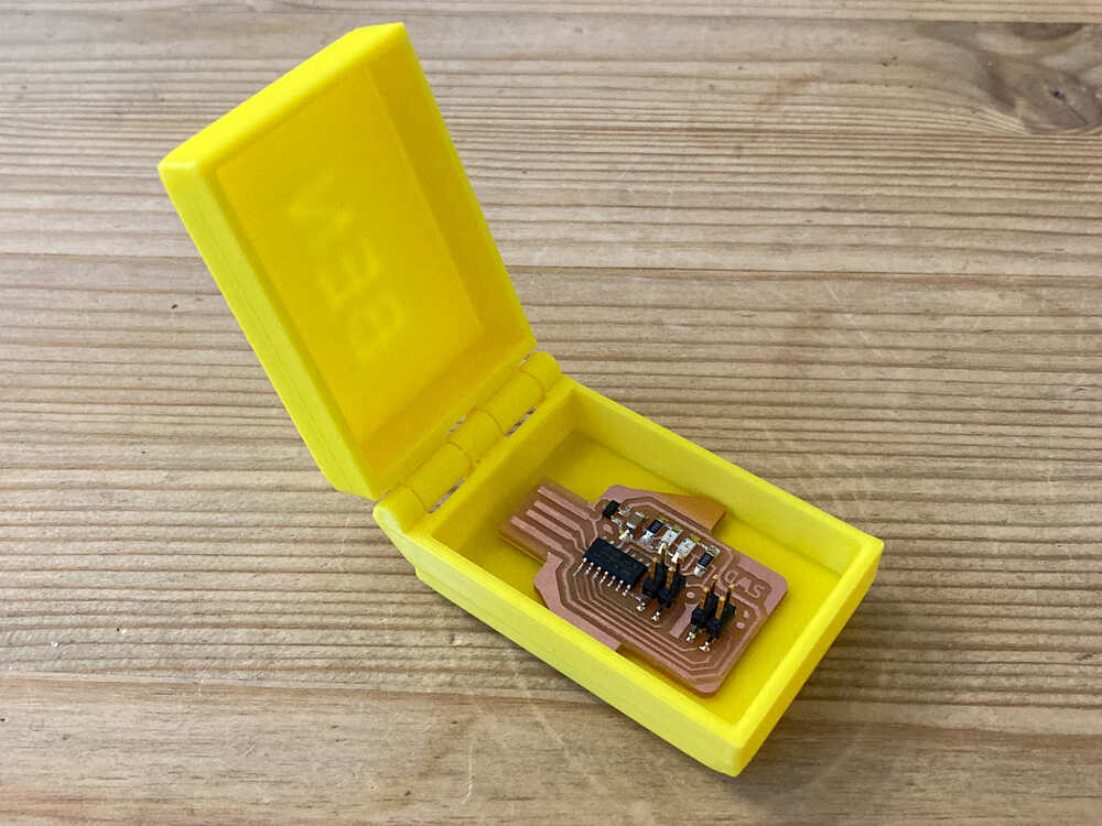
Final result
Scanning an object with Photogrammetry
A while ago I did build a chair for my son and I made it to look the same as the bigger chairs we have. It would be fun to scan his chair and print a third super small version.
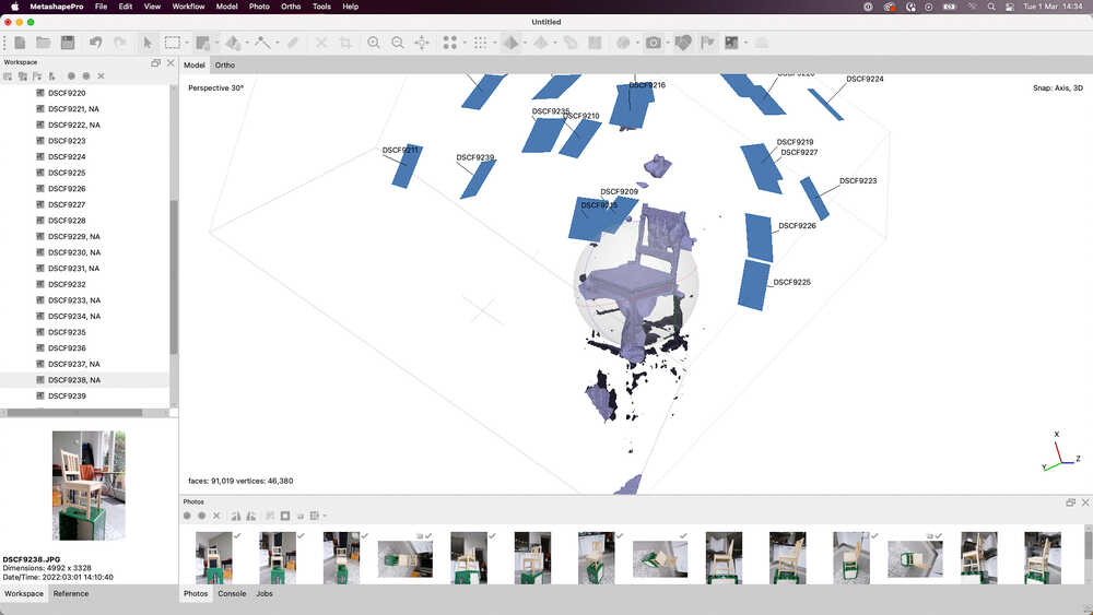
I will try to make the scan using photogrammetry. I’ve heard that meshroom is a good program but when I looked into it I found out that it doesn’t run on Mac OS. After a bit more googling I decided to try MetashapePro. It’s a paid program but they offer a 30 days free trial.
Once I downloaded and installed MetashapePro I did:
- Take a lot of pictures of the chair. I went around the object in circles: First I took the pictures looking up to the chair and each following round I took the pictures from a little bit higher up until I ended with a round where I was taking pictures down to the chair.
- Drag and drop pictures into MetashapePro
Workflow > Align Photos. WithAccuracy Lowthis runs pretty fast but with higher accuracies it can take 10s of minutes. The chair is visible in the generated point cloud but there was a lot of background (things around the chair) too.- I added selections to some of the pictures as described in this video. This should help to isolate the object from the background. It helped to isolate the object but when adding selections more pictures were unable to be aligned (program can not determine pictures position in relation to other pictures)
Workflow > Build dense cloud. This generated something looking like a chair but it’s far from perfect
After spending multiple hours trying out MetashapePro and not getting great results I decided to try out the 3D scanner that we have at the waag.
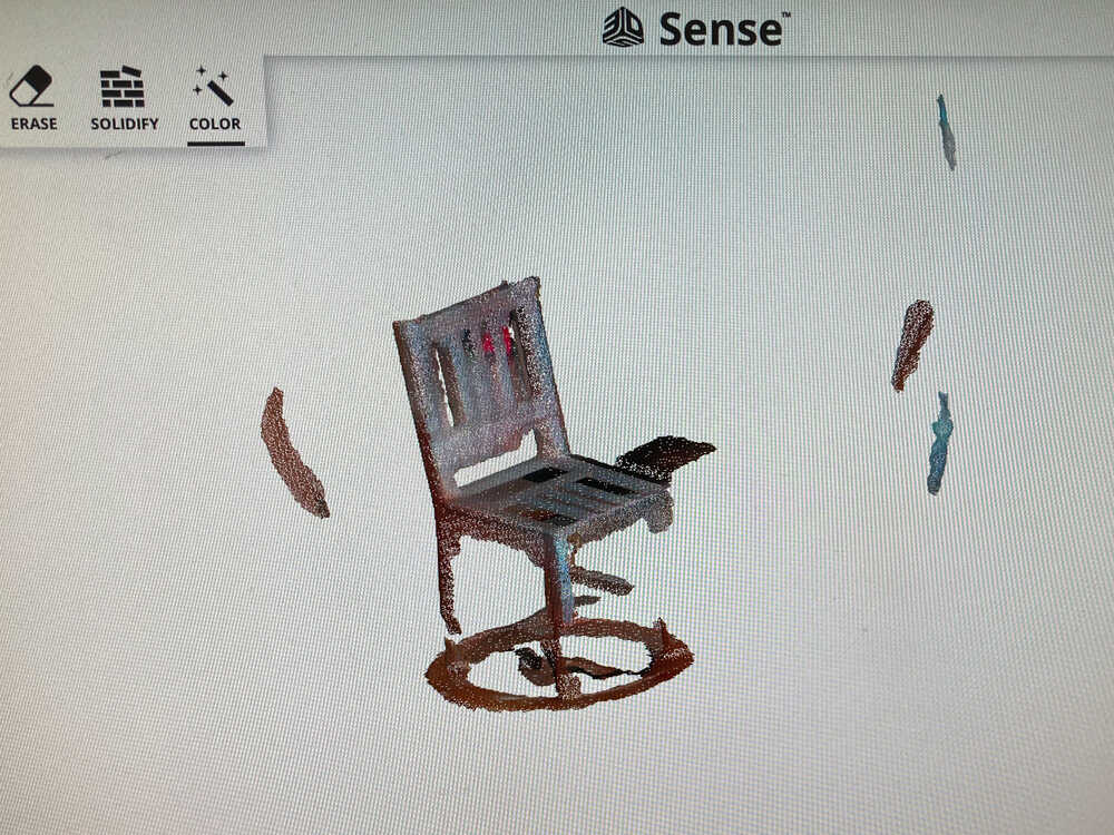
Scanning an object with a 3D scanner
In the fablab we have a 3D systems sense scanner. It’s not produced and supported anymore but it’s still working.
The scanner is easy to use and the software has easy tools to remove unwanted parts and solidifying the model but it’s difficult to get accurate scans.
The scanner easily looses track when not moving super slowly and sometimes it keeps track wrongly. In this image it’s combining 2 chairs in different positions (see back of the chair embedded in seating area)
Once the scan is complete it’s relatively easy to remove parts that are far away from the chair but imperfections withing the chair can not really be adjusted/corrected in this program.
This is the best scan I managed to make of the chair:
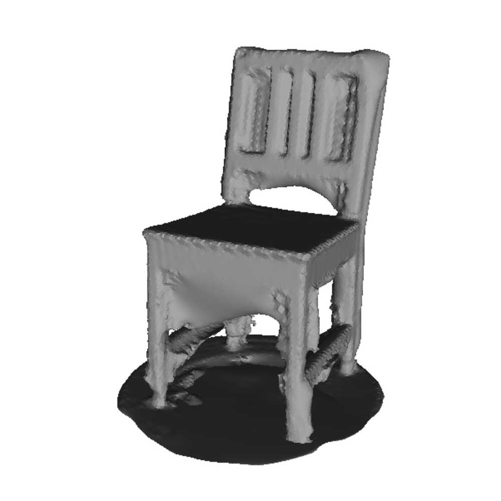
When I started scanning I was hoping that I would manage to produce a scan that can be printed but unfortunately at this point there’s still quite a while to go to get to a printable model.
Self adjusting heliostat 
I think I’m ready to build a first self adjusting heliostat using the prototypes I’ve built in the last weeks :-)
This is how I want it to work:
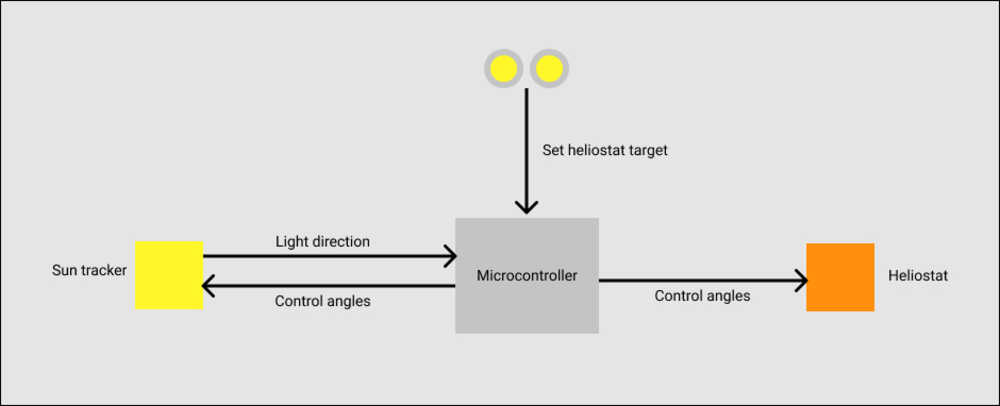
- The yellow pan tilt head acts as a sun tracker as I did in Computer Controlled Cutting
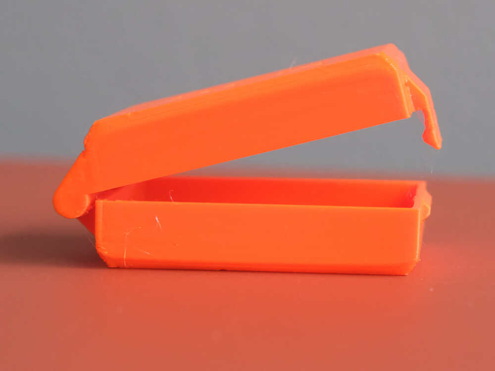
- The orange pan tilt head has a mirror mounted on it to act as a heliostat
- The heliostat target (position where light is reflected) can be set manually by turning the potentiometer knobs
- When the sun moves
- The sun tracker adjusts to point again towards it
- The heliostat adjusts to continue reflecting light to the same target (based on the angles of the sun tracker)
To create the setup described above I printed and assembled a second pan tilt head like the one I’ve built in the CAD week. Before printing it I adjusted the design slightly to include holes for the screws fixing one of the servos on the bracket to make assembly easier. Last time I did drill them after completing the print but it’s not so easy to drill hole without getting the plastic to melt and create an oversized hole.
I did as well design and print 2 knobs to easily adjust the potentiometers.
To control the second pan tilt head I added connectors for the extra 2 servos on the microcontroller stripboard.
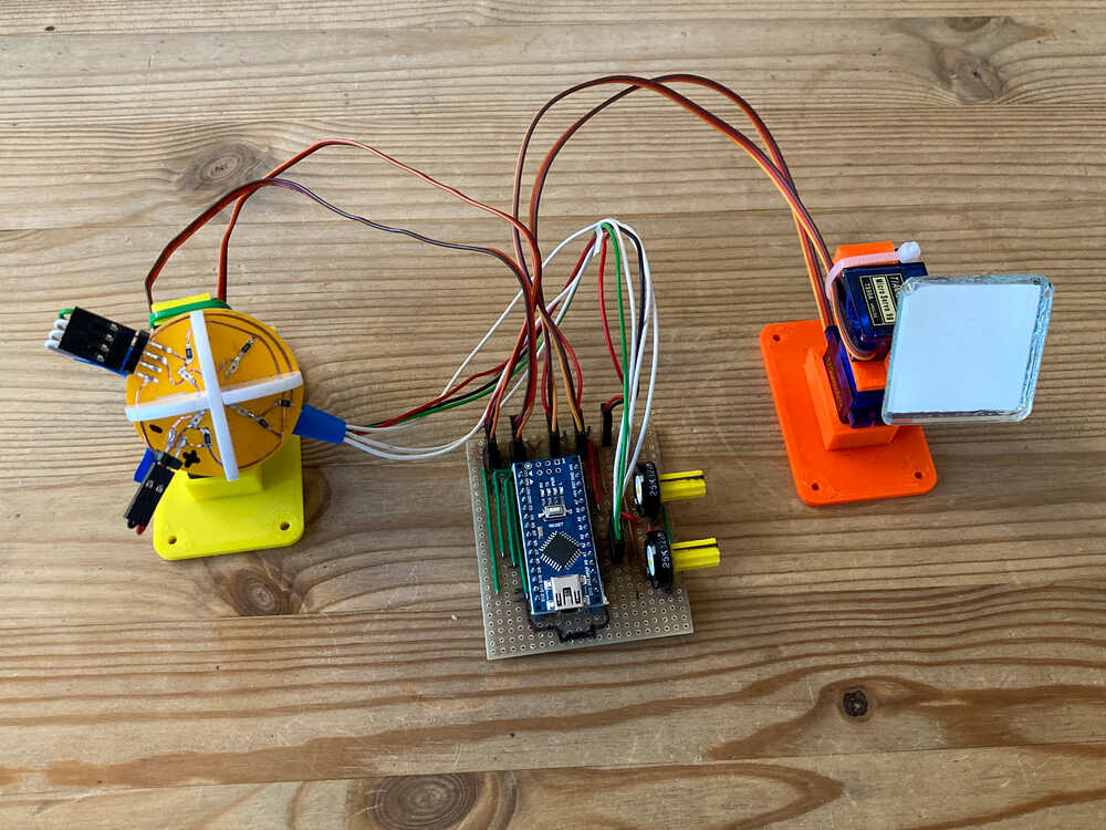
I did put everything together and managed to get the two heads (sun tracker & heliostat) to work individually. I didn’t get to write the code that adjusts the heliostat based on the sun tracker yet.
Retrospective
I’m happy that I managed to make a design of a hinge which prints well in one piece. That might be useful in the future.
This week I’ve been mostly working from home. That way I could use my printer and let the printers in the lab free for fellow students. It was great to have a fully dedicated printer but I missed going to the Waag. After all the time we’ve been working from home it’s a privilege to be able to get out of the house and work somewhere else. At the lab we’re mostly working individually but it’s still inspiring to have other people around and see what they’re working on. In the coming weeks I will again spend more time at the fablab.
I had many ideas for this week (A part is listed in the optional task). As usual there is not enough time to do everything. I’ve done some 3D printing before but I still learned new things this week and that makes it a success in my view.