7. Computer Controlled Machining
Planning
Tasks - Must
- In group: Test runout, alignment, speeds, feeds, and toolpaths for your machine
- Individually: Make (design+mill+assemble) something big
Tasks - Nice to
- 3D print handles for balance bike with flexible material
Execution
ShopBot milling machine
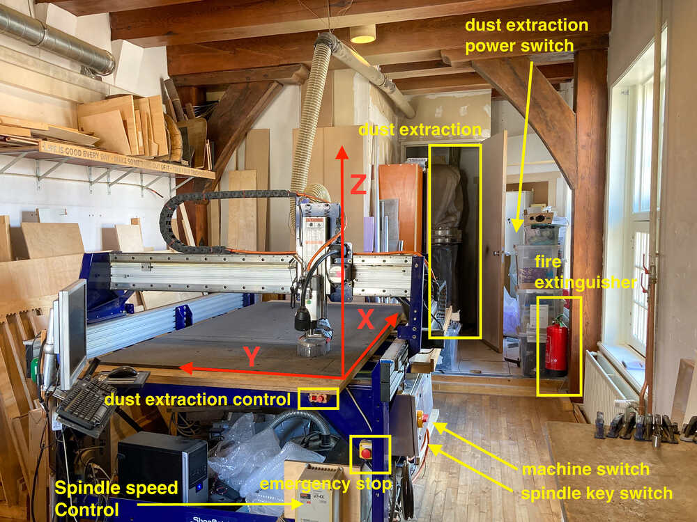
Safety
- Know escape routes: Main entrance & door to tower
- Know where the fire extinguisher is
- Know where emergency stop of machine is
- Make sure surrounding of machine is free. There shouldn’t be anything leaning against the machine
- Never touch the machine while it’s operating
Operation
Insert milling bit
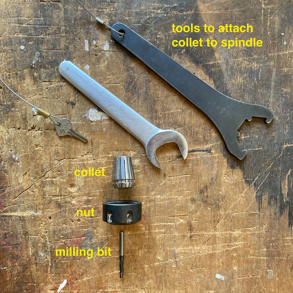
- Push nut onto collet until they click together
- Insert milling bit into collet
- Lower dust skirt to allow easier access to spindle
- Screw collet onto spindle and tighten using the dedicated tools
- Raise dust skirt and tighten wing nut to hold it in place
Turn on machine & Start software
Software will complain if machine is off as communication can not be established.
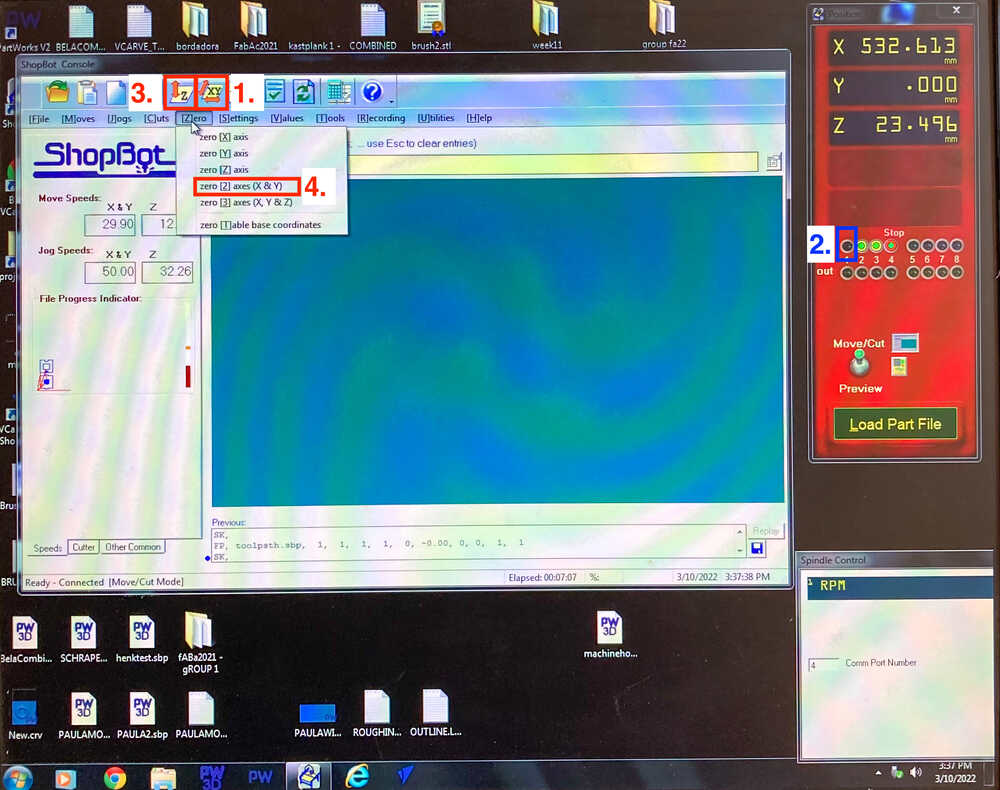
Home X and Y
Press button 1. to home X/Y : The machine will move to the X and Y end stops
Home Z
- Make sure there is no material on the machine. Z has to be homed on the sacrificial layer
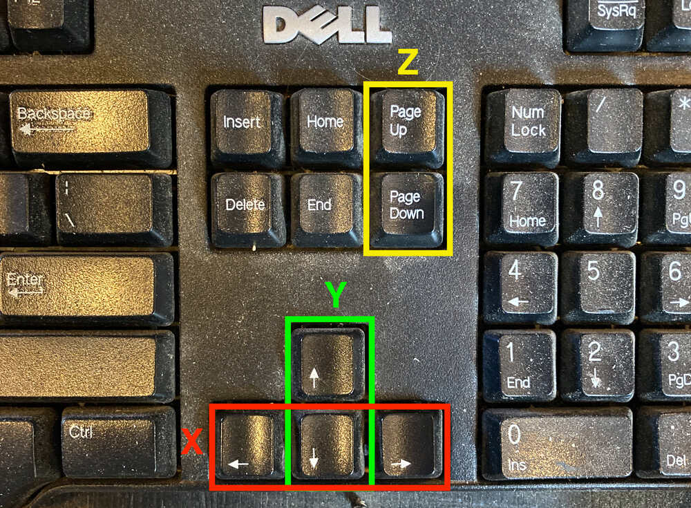
- Press
Kto open keypad that allows to move machine manually (with keyboard) - Manually move X/Y to good position for Z homing
- Test Z probe: Make sure
2.lights up when touching tool with Z probe plate - Press button
3.to home Z: Machine will move Z until tool touches probe plate - Raise Z axis manually
- Put Z probe plate back in holder (attached to spindle)
Place material
- Sand burs of fixing screw holes flat
- Make sure sacrificial layer is clean
- Place material
Job zero
- Move X/Y manually to position where job should start. Make sure not to cross the machine zero
- Take picture of coordinates
- Zero X/Y by selecting menu item
4.
Mill fixing screw markings
- Load path file for screw markings from USB stick
- Start dust extraction
- Turn on spindle & set speed to 18000 RPM
- Start job
Fix material
Fix material to sacrificial layer with screws where the markings are
Start milling
- Load toolpath file from USB stick
- Start dust extraction
- Turn on spindle & set speed to 18000 RPM
- Start job
Group assignment
Henk showed us how to create toolpaths in VCarve and then we did mill this test model.
VCarve
To create the toolpaths to mill the test model we made the following steps in VCarve
Setup:
- set units to
mm - select material
width,heightandthickness. Measure thickness in multiple points and take average - Set
zeroto be on top of sacrificial layer (Checkbox next to thickness) - Set XY Datum position: Select bottom left checkbox (On the machine it’s the corner where the on switch is)
Tool
We created a tool with the following settings that we’re going to use for all the toolpaths
| Parameter | Value |
|---|---|
| Tool diameter | 5 mm |
| Pass depth | 2.5 mm |
| Stepover | 15% |
| Spindle speed | 18‘000 RPM |
| Feed rate | 60 mm/sec |
| Plunge rate | 20 mm/sec |
Design
- Import 2D design (e.g. DXF, pdf)
- Add screw markers to design (
5 mmdiameter circles). We’re going to mill this markers first and then screw the material to the sacrificial layers with screws where the markers are - Create
Dog-BoneorT-Bonefillets so that parts can fully slot together
Screw markers toolpath
- Create Drilling toolpath
- Cut Depth
1 mm
- Cut Depth
- Save toolpath to file
Toolpaths
- Create Pocket toolpath (not cutting all way through)
- Select tool created earlier
- Select cutting depth (
6mm) - Select Clear Pocket
offsetandclimb
- Create Profile toolpath (cutting through) for inside jobs
- Select tool created earlier
- Start Depth
0 mm - Cut Depth
17.5 mm(material thickness) - Machine vectors
insideandclimb - Add tabs
- Length
12 mmand thickness3 mm - Click on design where tabs should be added
- Length
-
Create Profile toolpath (cutting through) for outside jobs
- Select tool created earlier
- Start Depth
0 mm - Cut Depth
17.5 mm(material thickness) - Machine vectors
outsideandclimb - Add tabs
- Length
12 mmand thickness3 mm - Click on design where tabs should be added
- Length
-
Save toolpaths to file (In the order they’re here: pocket, inside, outside)
Mill test part
We ran the screw markers toolpath first with the material laying on the sacrificial layer without being fixed. Once this is complete we screwed the board to the sacrificial layer and then we ran all other toolpaths.
Half way through the milling process we changed the feed rate to 90 mm/sec.
The cuts in the direction of the wood grain (of the top plywood layer) turned out cleaner and with less tearout than the cuts perpendicular to the grain.
The cuts made at 90 mm/sec were a bit “wavy”. The ones made at 60 mm/sec were cleaner and more straight.
Climb vs conventional
Saco made a test design with two squares, in one he used conventional and in the other climb milling to see if we could see any difference.
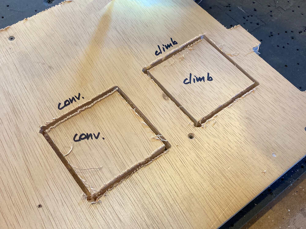
With the used parameters and this test model we couldn’t see any difference.
Balance bike 
Inspiration
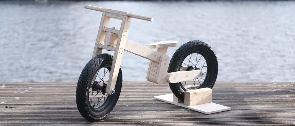
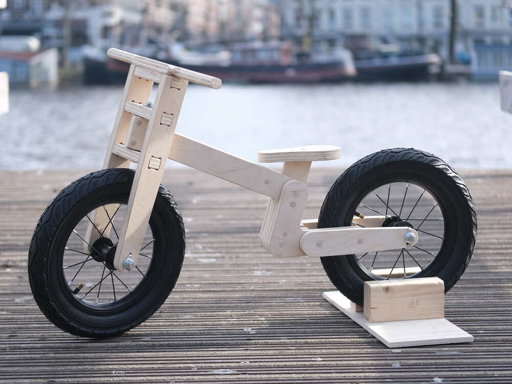
As my individual assignment I want to make a balance bike for my son.
I started by looking at balance bikes on the internet for inspiration. I found this balance bike and I really like the shape of the frame.
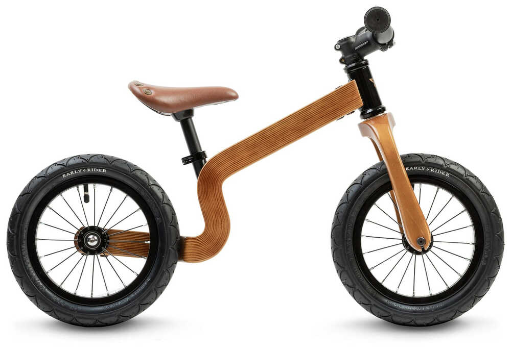
This bike was built with a different technique than the one I’ll use but I’ll try to come up with a design that has a similar curve in the frame.
Design
I started by measuring the dimensions and angles of a balance bike we have at home. I will take these parameters as a starting point for my design.
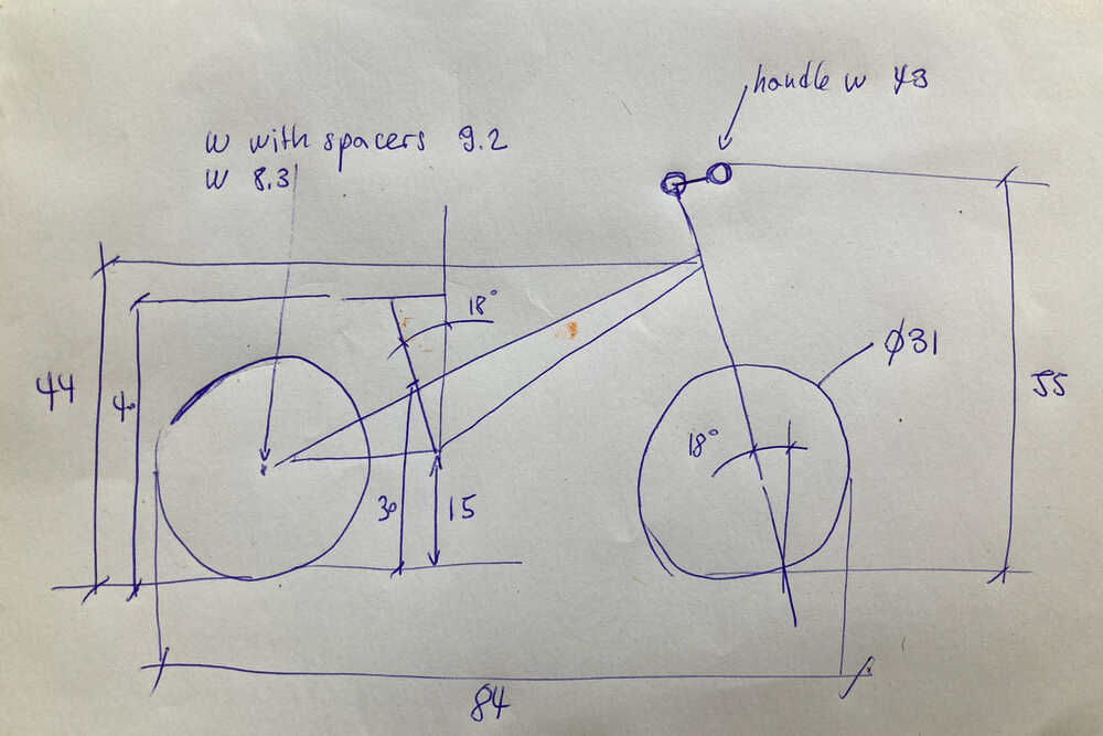
I created a sketch in fusion based on the measurements I took. This sketch didn’t contain any bike to start with but just parameters which were already fixed like wheel size, fork angle, total length…
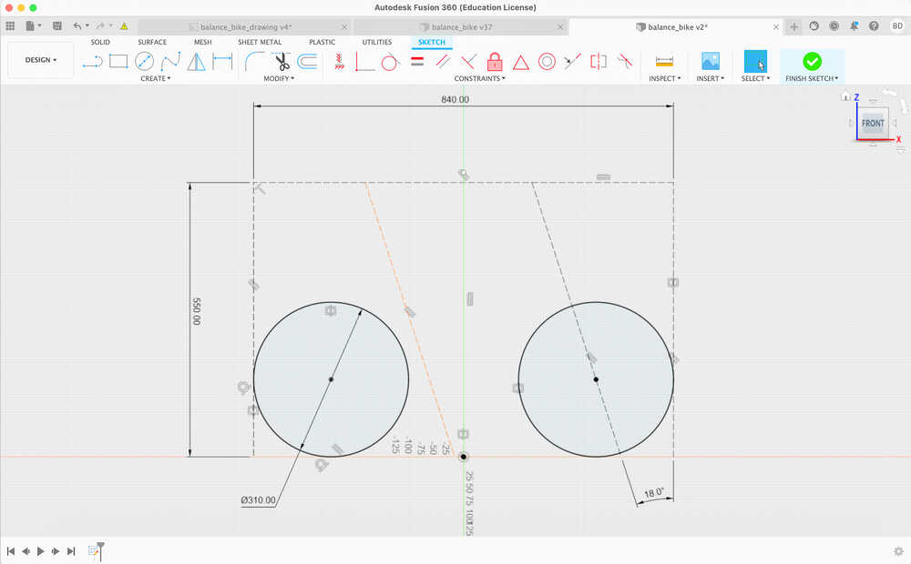
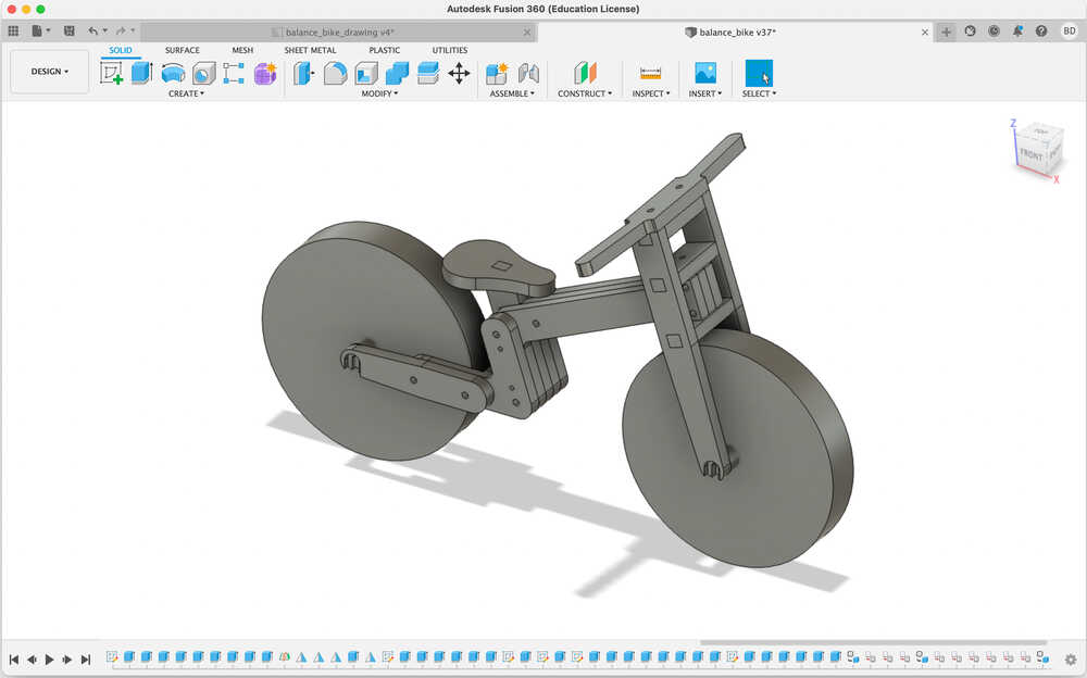
These construction lines and wheels helped me to get started designing the bike. This what I finally came up with:
Toolpaths
I created the toolpaths in VCarve as we did in the group assignment.
First I exported my fusion 360 drawing as PDF and then imported it into VCarve.
Vectors not connected
I was not able to create toolpaths for some of the parts because they consisted of multiple vectors which were not connected. I fixed these vectors directly in VCarve using the Join vectors tool.
Double lines
In fusion I created some of the sketches on top of body faces (right click face > Create sketch). The objects created from such sketches had double lines in some places. For most of them I managed to remove the double lines in VCarve. For the bikes handlebar there were a lot of double lines and I didn’t manage to fix it in VCarve. To make it work I made a new sketch in fusion on the XY plane (NOT on top of a body face).
Once I fixed all the vectors I added markers (5 mm diameter circles) for the screws to fix the material to the wasteboard and created a toolpath to drill 1 mm holes at these positions.
Then I added dogbone fillets in the positions where parts have to fit together.
Once everything was ready I created toolpaths for
- Holes
- Inside cuts
- Outside cuts
Milling
First of all I did run the toolpath to drill the screw markers with the material laying on the wasteboard without fixing it. Then I screwed the material to the wasteboard wherever there is a marker.
Once the material was fixed in place I milled some test models to find good clearances to make joints fit nicely.
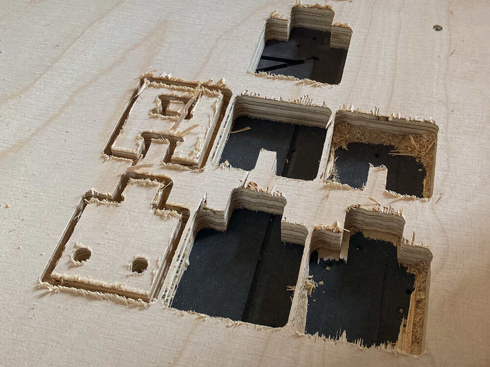
In made my design so that both parts of the joint had exactly the same measures and then I tweaked the allowance offset parameter in VCarve until I got a good fit. I ended up using -0.4 mm.
Tear out
The quality of the cuts in the test models was not great. There was quite a bit of tear out. Because we’re sharing the time on our ShopBot between 8 students I wasn’t able to spend too much time tweaking the settings to get clean cuts. I’d like to come back to this in the future to try different settings to get to a better finish.
Tabs
I added tabs in VCarve. At first I made them 3 x 5 mm but some of them broke during the machining. To stop that from happening I went back to VCarve and made them 5 x 12 mm
Once I was happy with my test models I milled the bike
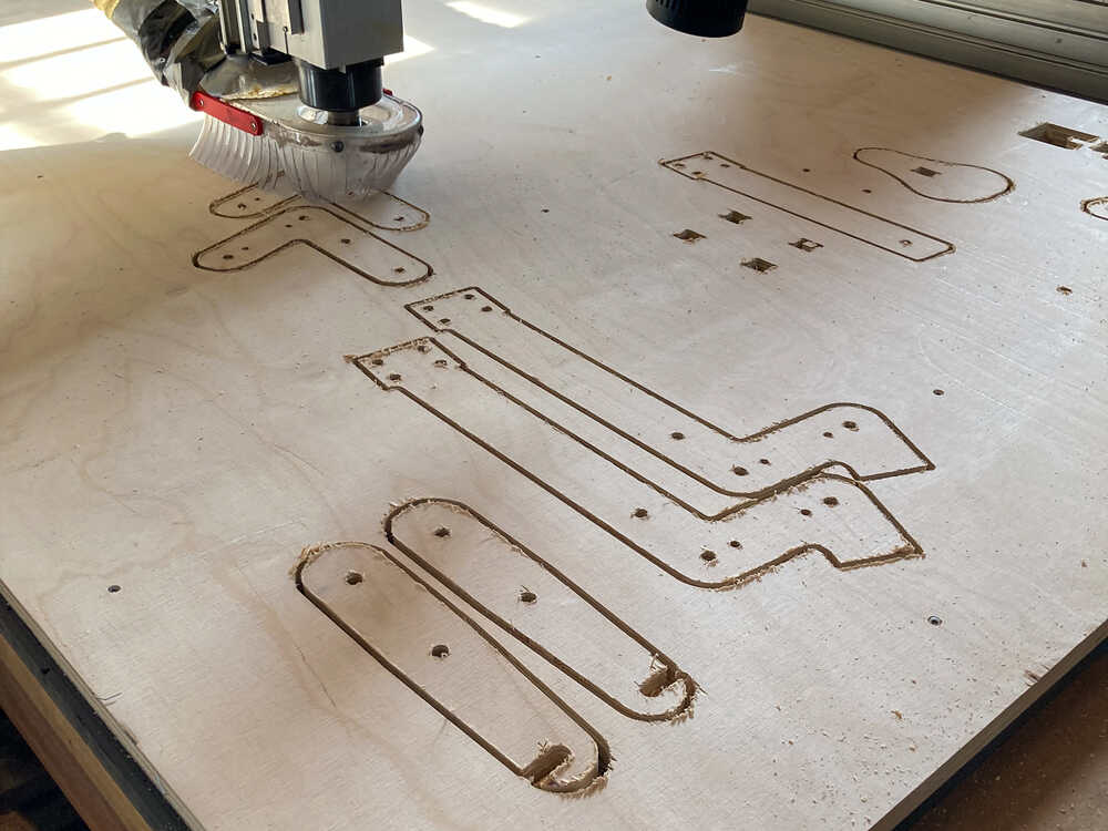
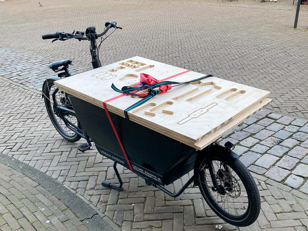
Then I took the parts of the bike I just milled home… by bike :-)
Post processing & Assembly
Now that I had all the parts it was time to sand them
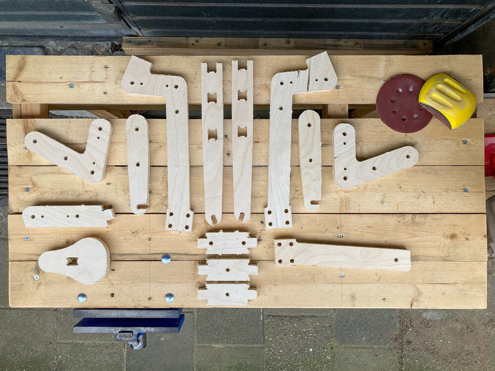
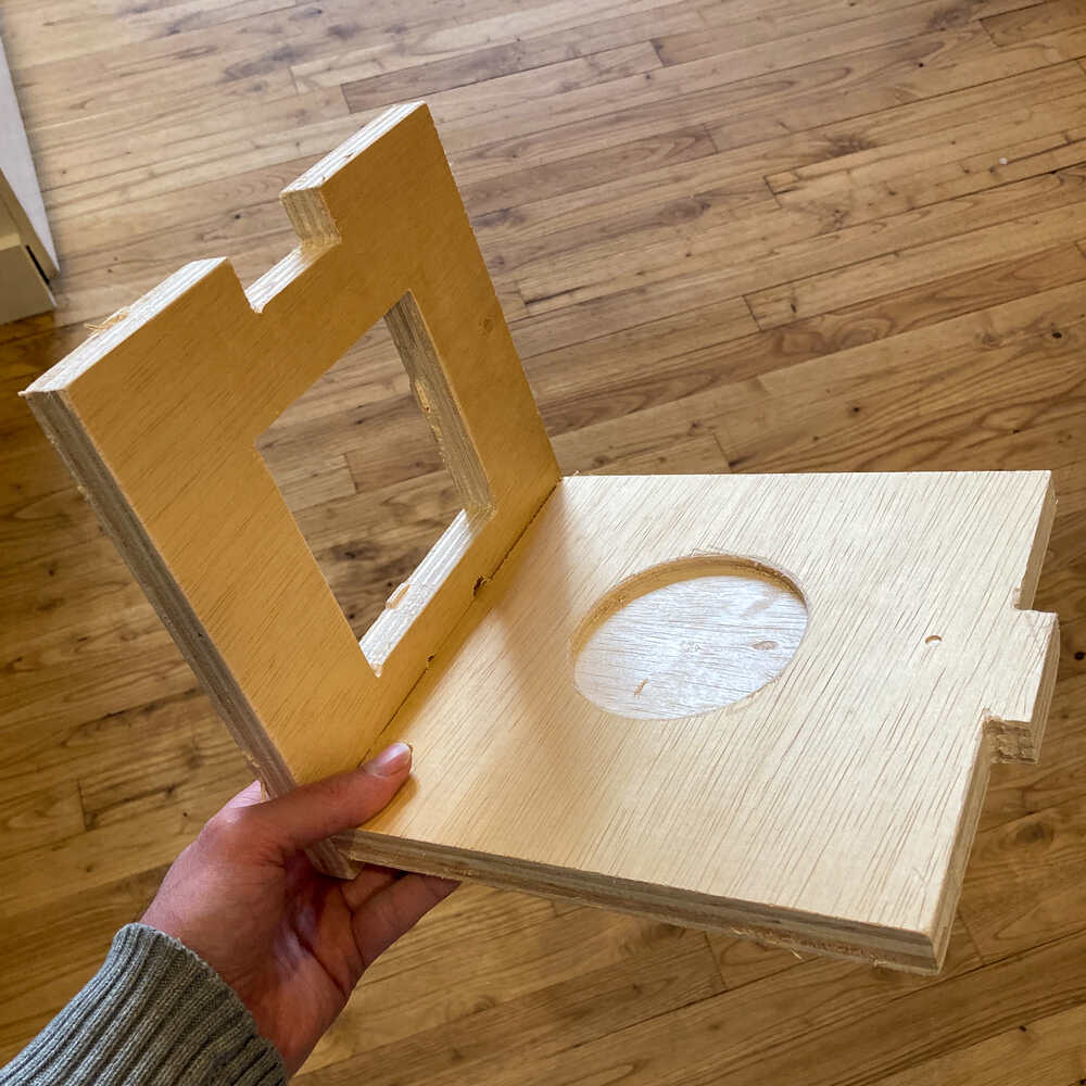
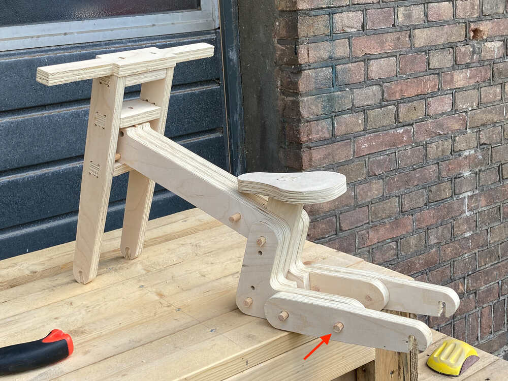
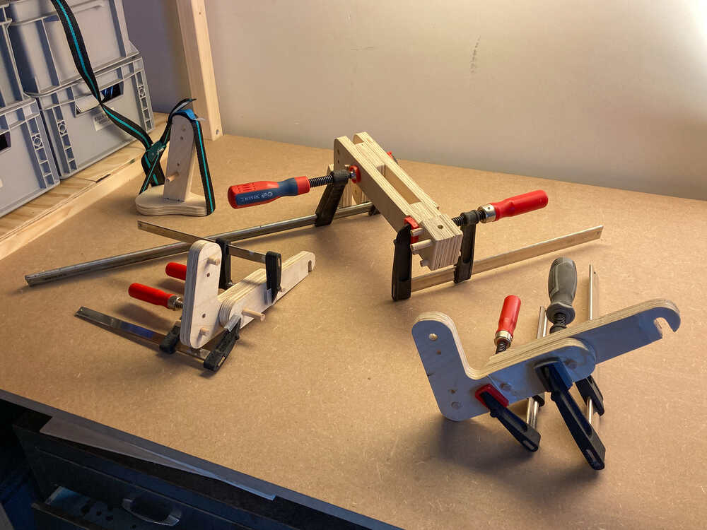
Once I completed the sanding I made a first test assembly to see if everything fitted as planned.
In my design I included holes to connect the pieces with a 9 mm round wood rod. These rods really helped for test fitting and they made it super easy to align the parts for gluing.
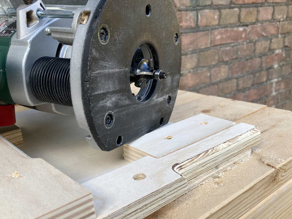
There are sections of my parts that I want to be thinner than the original 18 mm material. In my design I include these thinner sections and was planning to mill them on the CNC machine. My time was limited when I was creating the toolpaths in VCarve so I decided to focus on full-depth cuts. To still get to the desired measures I made the marked sections thinner using my hand router.
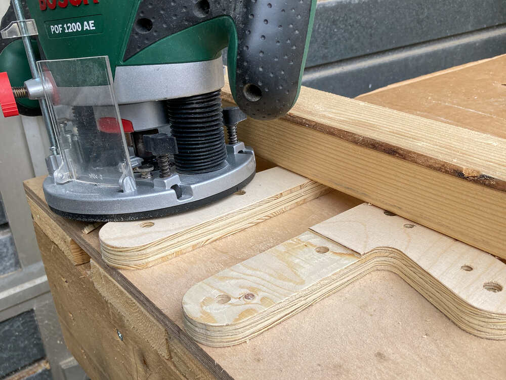
I did as well make the handles round using a roundover bit
Once I had all the parts ready I glued them up
The next morning I assembled everything and ended up with this nice bike :-)
Retrospective
This week has been really intensive but it’s really satisfying to build something big. I underestimated the time it takes to get all the vectors ready for VCarve. Next time I will plan more time for this task.
Once the CNC machine was done cutting the parts I was at a good point but still far from being done. I spent more than a day on postprocessing, manual adjustments and assembly. Even if it took a while I really enjoyed the manual work which kept me away from the computer :-)
It feels empowering to be able to make big objects on a CNC machine. I’m looking forward to using the ShopBot again.