2. Computer-Aided Design
Planning
I don’t know in detail yet how my final project will look. The final design will be the outcome of multiple prototypes, experiments, failures and improvements. Instead of spending time on something uncertain and far in the future I will model a first prototype of my final project. By doing so I will be able to build it straight away and use this first prototype in the following weeks to try out different aspects of my final project.
Tasks - Must
- Select CAD program
- Make model of final project
Tasks - Nice to
- Animate model assembly
- Build first prototype of final project
- Come up with workflow to resize videos for web
- Animate model movement
- Simulate sun reflection in mirror
Execution
Select 3D software
The introduction lessons to Fusion 360 and FreeCAD gave me a first taste of these programs as I’ve never used them before.
Until now OpenSCAD has been my go-to program to make 3D models. As I already know it I won’t use it this week an rather focus on a new program.
While following along in the introduction lessons the Fusion 360 user interface felt more intuitive than the one of FreeCAD.
I will focus on Fusion 360 this week and use it to make my models.
Final project prototype 3D model 
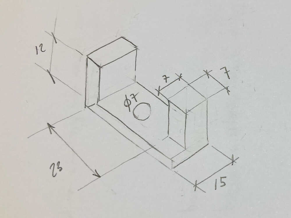
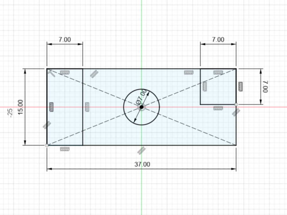
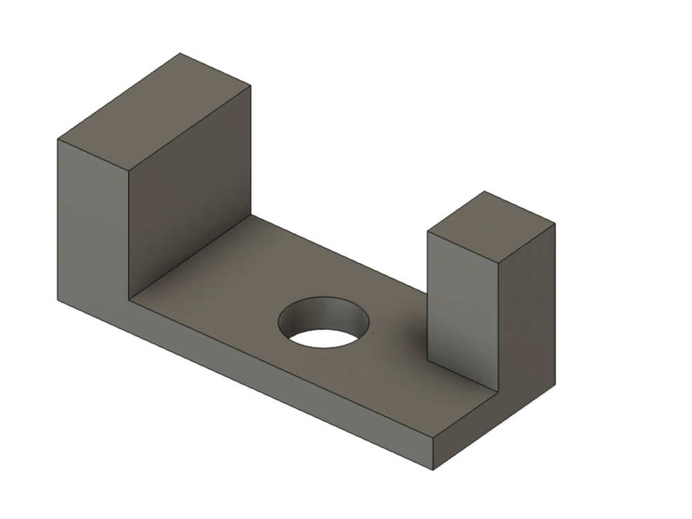
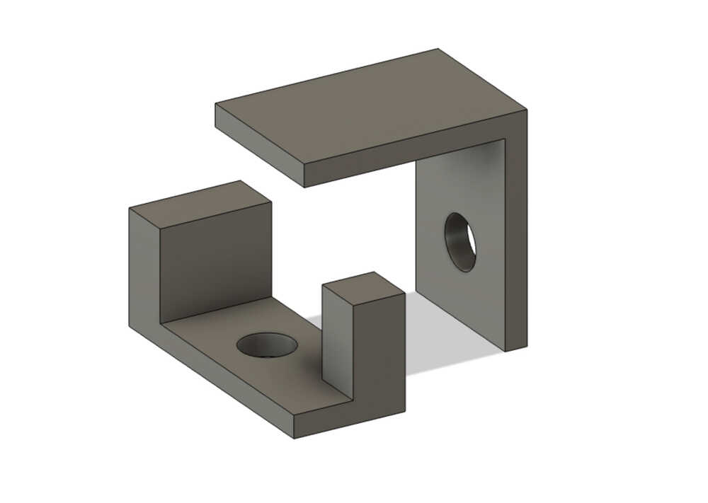
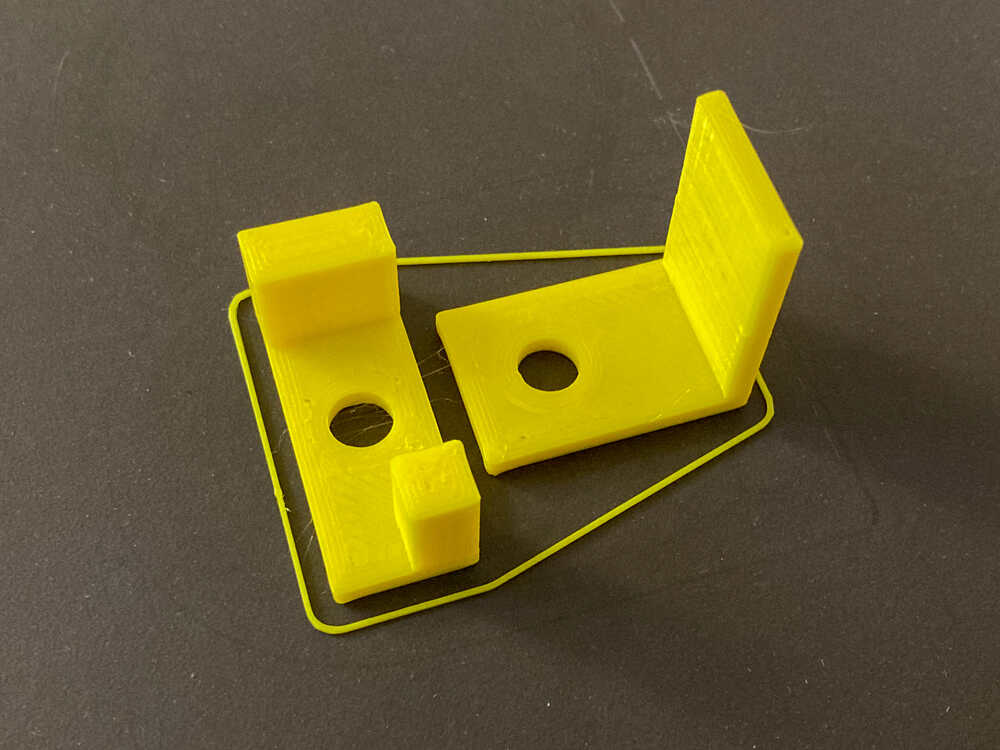
As a first prototype of my final project I will model a simple pan-tilt mechanism with two servos.
I did proceed in the following way:
- Make a draft on paper to figure out how the bracket should look and what the dimensions should be
- Create sketch in fusion
- Extrude different sections of the sketch to different heights
- Export STL:
Left click on body > Save as mesh > Select format and refinement level
Animation
I started with the components of my model randomly positioned in space but I soon realized that it’s easier to start with all components in their final (assembled) positions.
To get all the components aligned in their final position I used Align (Design > Solid > Modify > Align)
I created the animation with these steps:
- Manual Explode. By using the manual option instead of auto I was able to select in which axis each component gets exploded (
Transform > Manual explode) - Reverse Storyboard. This gives me an animation of the components assembling instead of exploding outwards (
Right click on Storyboard > Reverse) - Rotate. 270 degree rotation in the z axis
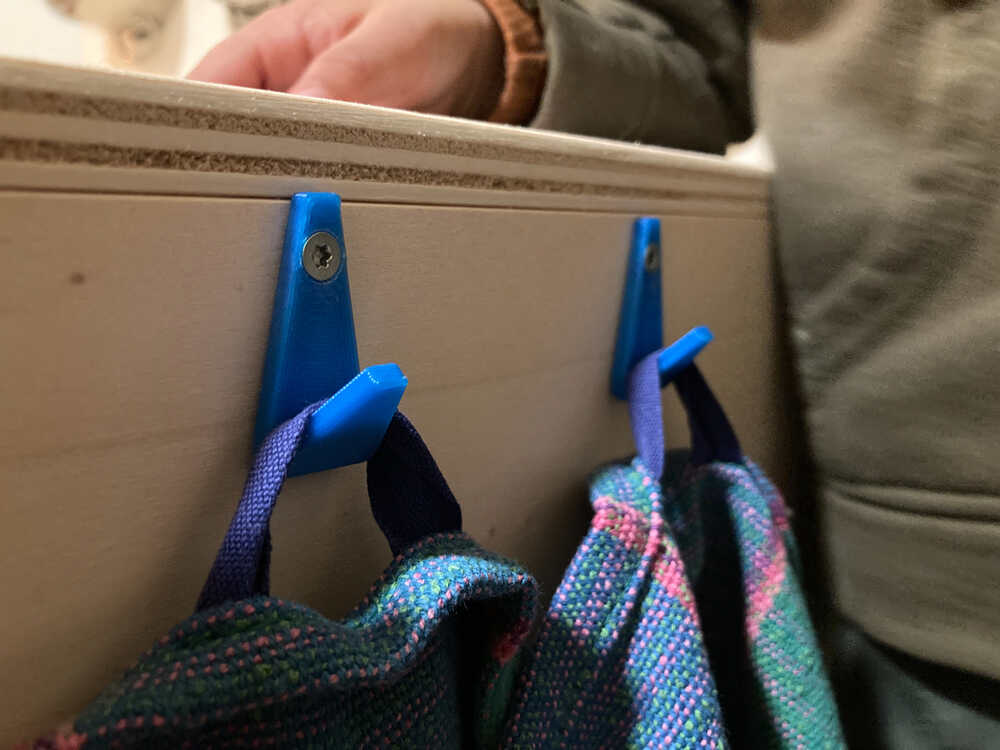
Kitchen towel hook 3D model 
The brackets for the pan-tilt mechanism were rather easy to model as all the parts could directly be extruded from the sketch. I decided to make a second model that is parametric and can not be simply extruded from the sketch. I’ll take this as an opportunity to model hooks to hang kitchen towels as I need a couple of them.
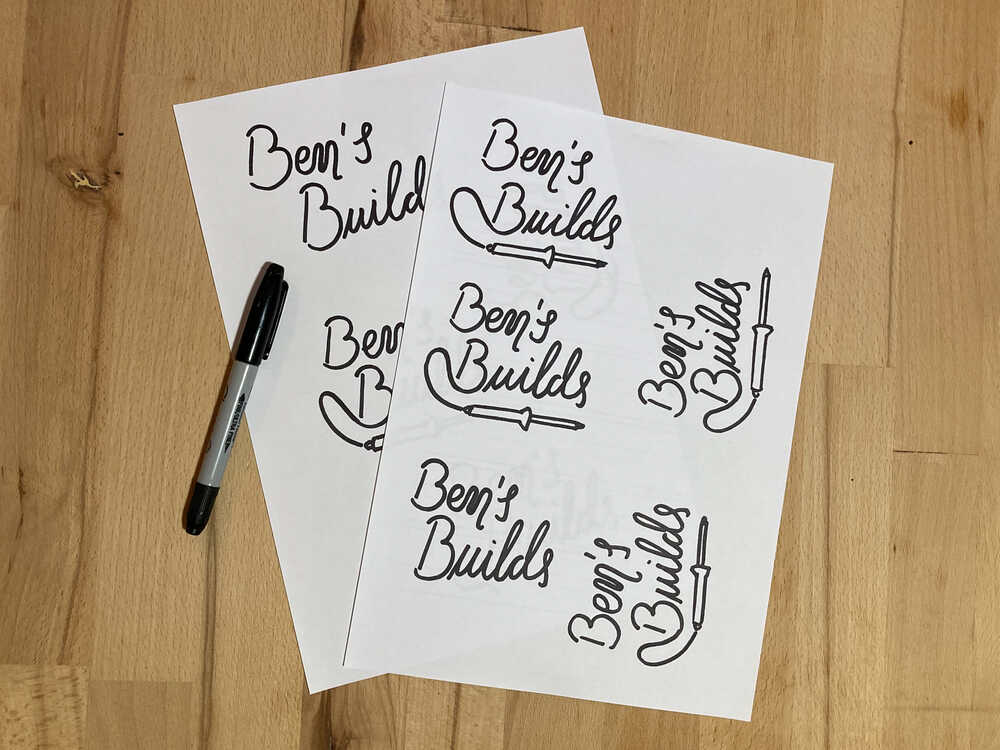
This is a first draft of how I want the hook to look like:
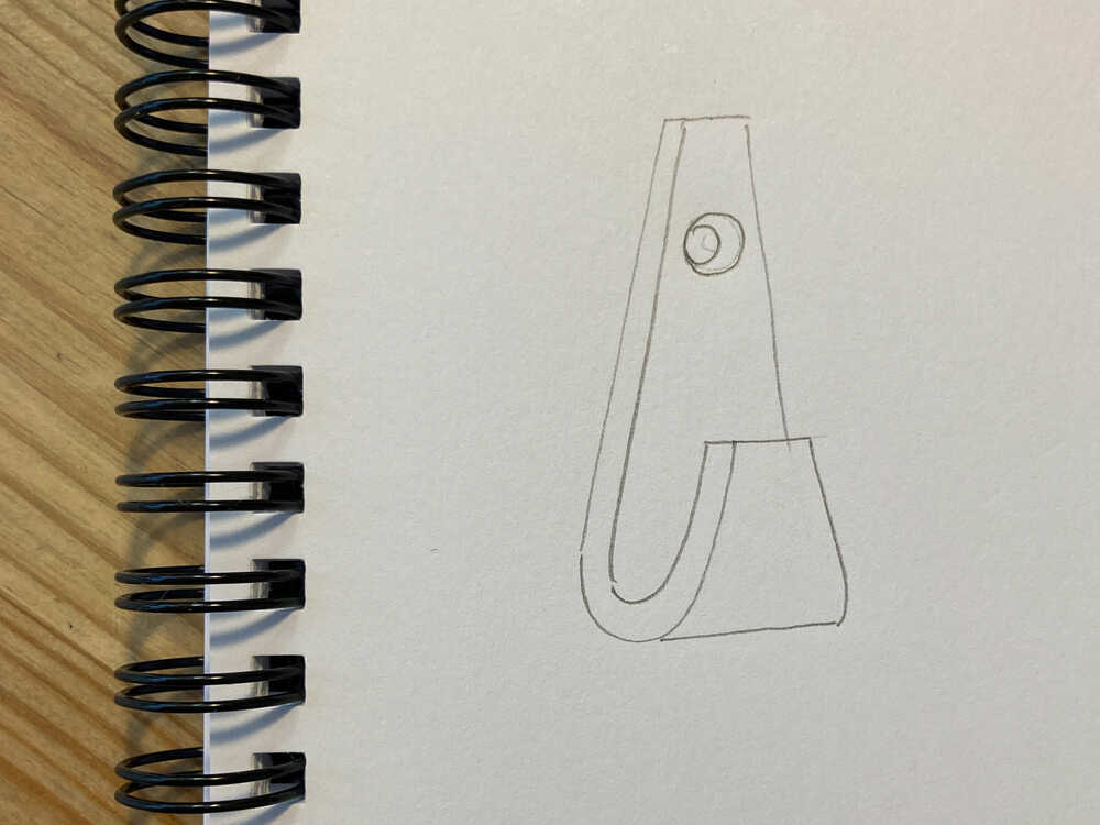
It would be siple to create a hook like this as I could just make a sketch with a curve and then extrude it.

But what’s the best way to create a model of an object which has non-straight features on more than 2 axes?
In some cases it’s possible to use 2 sketches and intersect them like in this example:
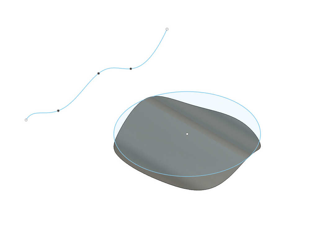
- Create spline sketch
- Extrude spline to surface
- Create circle sketch
- Extrude circle to solid and use intersection tool
- Resulting body is intersection between spline surface and circle extrusion
Fail
I failed to design the hook with this approach as the curve of the hook folds over itself:
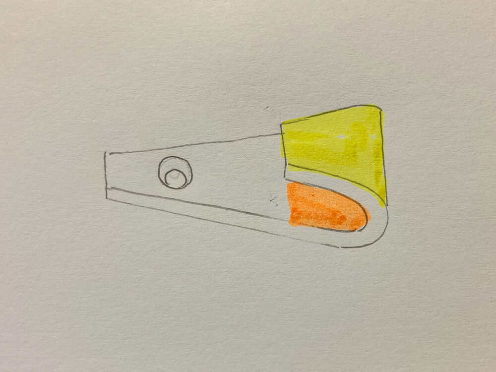
The yellow area folds over the orange one and they don’t have the same shape
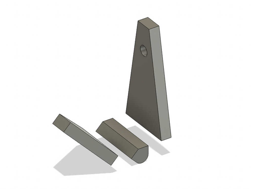
I managed to model the hook with the second approach: Extrude the following 3 bodies and then align them:
- Main body
- Tongue
- Fillet to combine the other 2 parts
I 3D printed the hooks and they’re already in use:
Use of parameters
- specify parameters (
Design > Solid > Modify > Change parameters) - Type parameter name in dimensions field
2D vector logo 
I want to use a 2D vector program to create a logo.
The selection of the program was a bit easier here than for 3D as I did hear good things about inkscape and it’s free. I’d say that’s good reasons to give it a try.
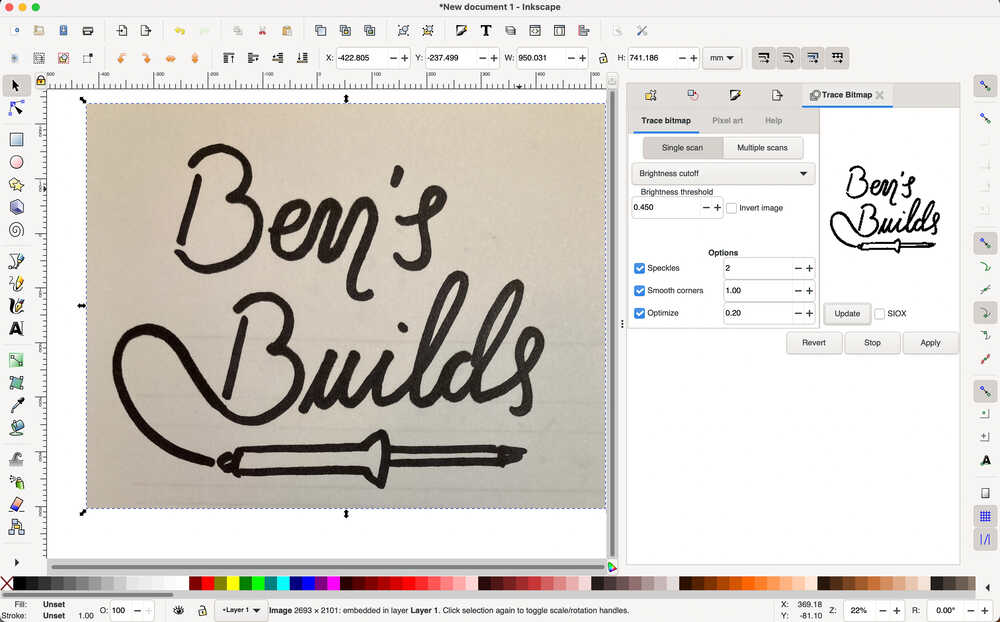
When I started to sketch the logo on paper I wondered If I could draw it by hand and then use the program to transform it into a vector graphic. It turns out that that’s possible so I will try that.
This is a overview of the steps I followed to create the final SVG:
- Make sketches to figure out how I want the logo to look
- Draw the logo again and again until I have a version I’m happy with
- Take a picture, open it in inkscape (just drag and drop image into empty inkscape document)
- Transform the picture into a vector graphic (with help of this youtube video):
Path > Trace bitmapand then chooseSingle scan > Brightness cutoff > 0.45 Brightness threshold - Select
Edit path by nodestool and remove/adjust vector points in some places to have smoother lines - Export SVG
Build final project prototype 
Models are nice but things get exciting when you turn them into real objects. That’s why we’re doing Fab Academy, right? I know that the focus of this week is modeling but I just couldn’t resist… so I turned the model into a real object :-)
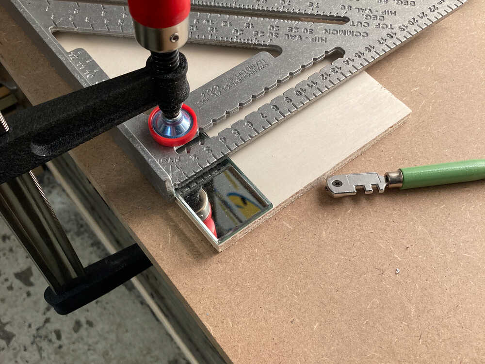
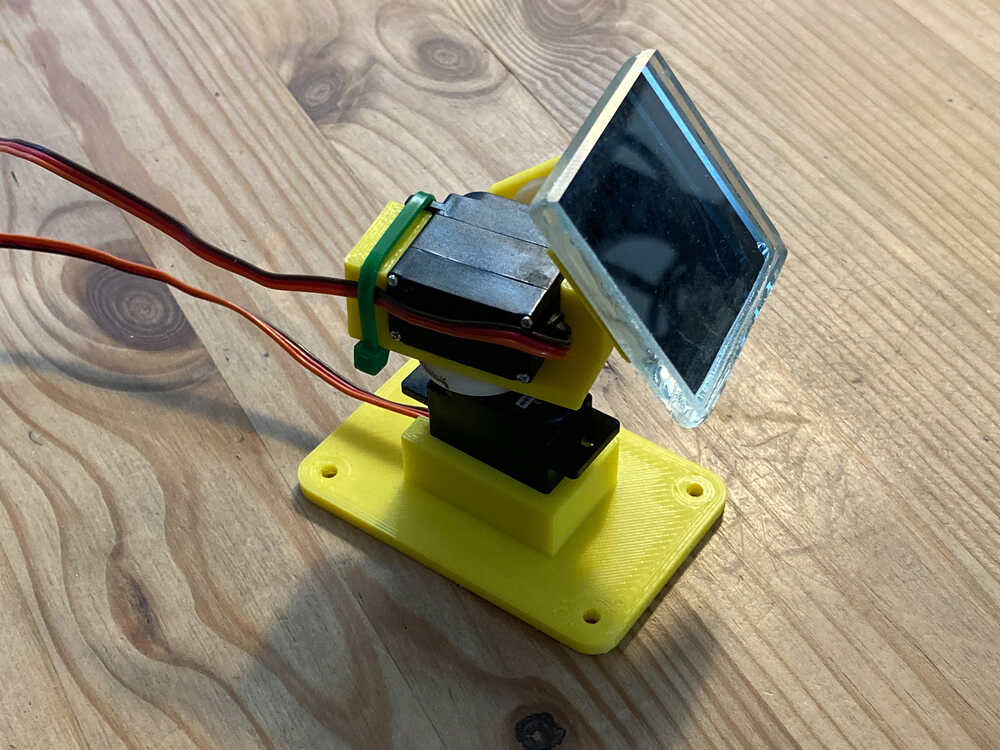
- I printed the brackets for the pan-tilt head with my Prusa Mini
- I cut a big mirror to get a small piece to attach to the pan-tilt head
- Assembled pan-tilt head
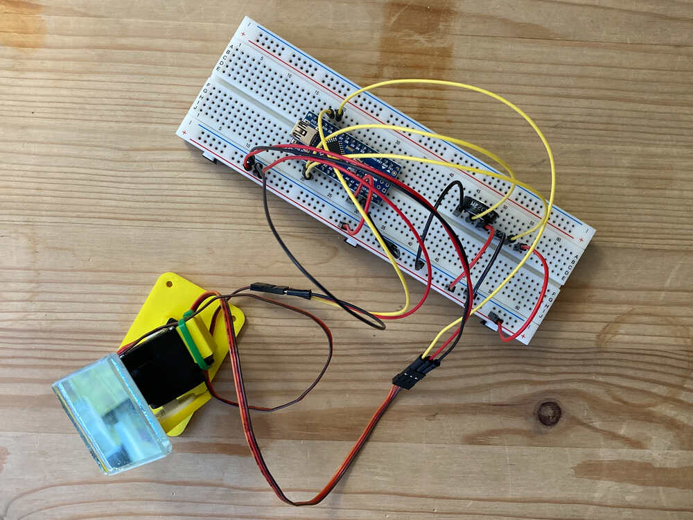
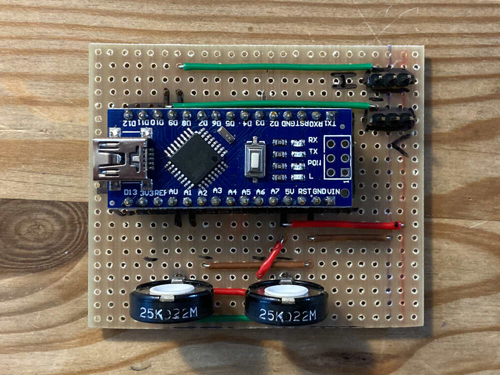
- Prototyped servo control circuit on breadboard
- Made servo control circuit on strip board
- Programmed microcontroller
First prototype of my final project in action:
Resize videos
Now that I have my first video it’s time to come up with a simple setup to resize videos. I will use a similar setup to the one I use for images:
- Create
videos/rawfolder for raw videos - Excluded folder from version control by listing it in
.gitignore - Create
resize_raw_videos.sh
The script will use ffmpeg which I installed with brew: brew install ffmpeg
I will use the snippet below which I copied from here here
ffmpeg
-i input_video # input video
-vcodec libx264 # set video codec
-b:v 1000k # set video bitrate to 1000 kbit/s
-vf scale=-2:1080 # resize height to 1080 (and width accordingly to keep aspect ratio)
-acodec mp2 # set audio coded
-b:a 256k # set audio bitrate
-ar 48000 # set the audio sampling frequency
-ac 2 # set the number of audio channels
output_video.mp4 # output video
Retrospective
I really enjoyed this week. By building a first prototype of my final project it was a good combination between learning new programs and actually building something. I’ve mostly used fusion 360 this week and I was positively surprised by how easy it was to get started and design first parts.
Action items from last week
- Remember to take a quick break every hour or so: I managed to take more regular breaks this week but there is still room for improvement. Breaks are a good time to take a step back from the task I’m working on. This helps to decide wether it’s worth continuing or rather trying another approach or switching task.
- Check my calendar daily: done