15. Wildcard
Planning
Tasks - Must
- Group: Make composite test coupons
- Design and produce something with a digital fabrication process (incorporating computer-aided design and manufacturing) not covered in another assignment, documenting the requirements that your assignment meets, and including everything necessary to reproduce it
Tasks - Nice to
- Communicate with the motor control board wirelessly
Execution
Group assignment
Henk gave us an introduction into composites.
A composite material consists of multiple individual materials which fall in two main categories: the matrix (binder) and the reinforcement.
As matrix we’re going to use SMOOTH-ON Tarbender. According to the Safety Data Sheet it’s necessary to ensure good ventilation, wear gloves and eye protection.
As reinforcement we have multiple materials to choose from. Together with Saco we decided to experiment with fiberglass applied around a cardboard core.
Is it possible to make a cardboard structure and then make it strong by applying fiberglass around it? We made 3 experiments to find out more:
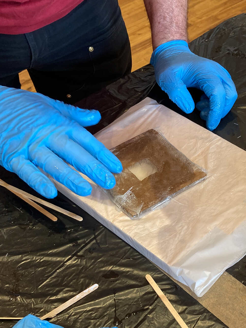
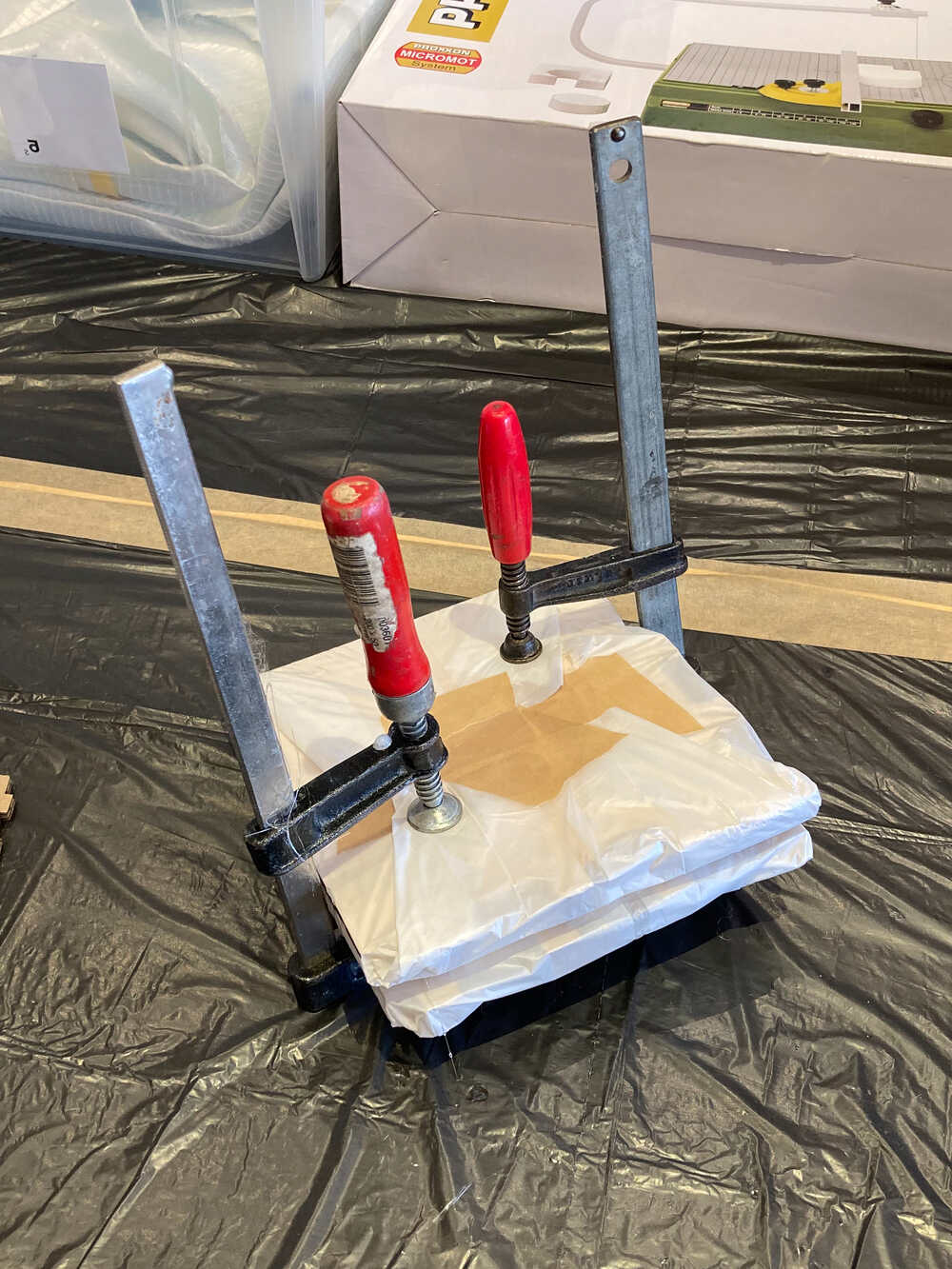
- Fiberglass applied around a cardboard square, pressed together with two wood plates for curing
- Fiberglass applied around a cardboard square, left curing as-is without external pressure
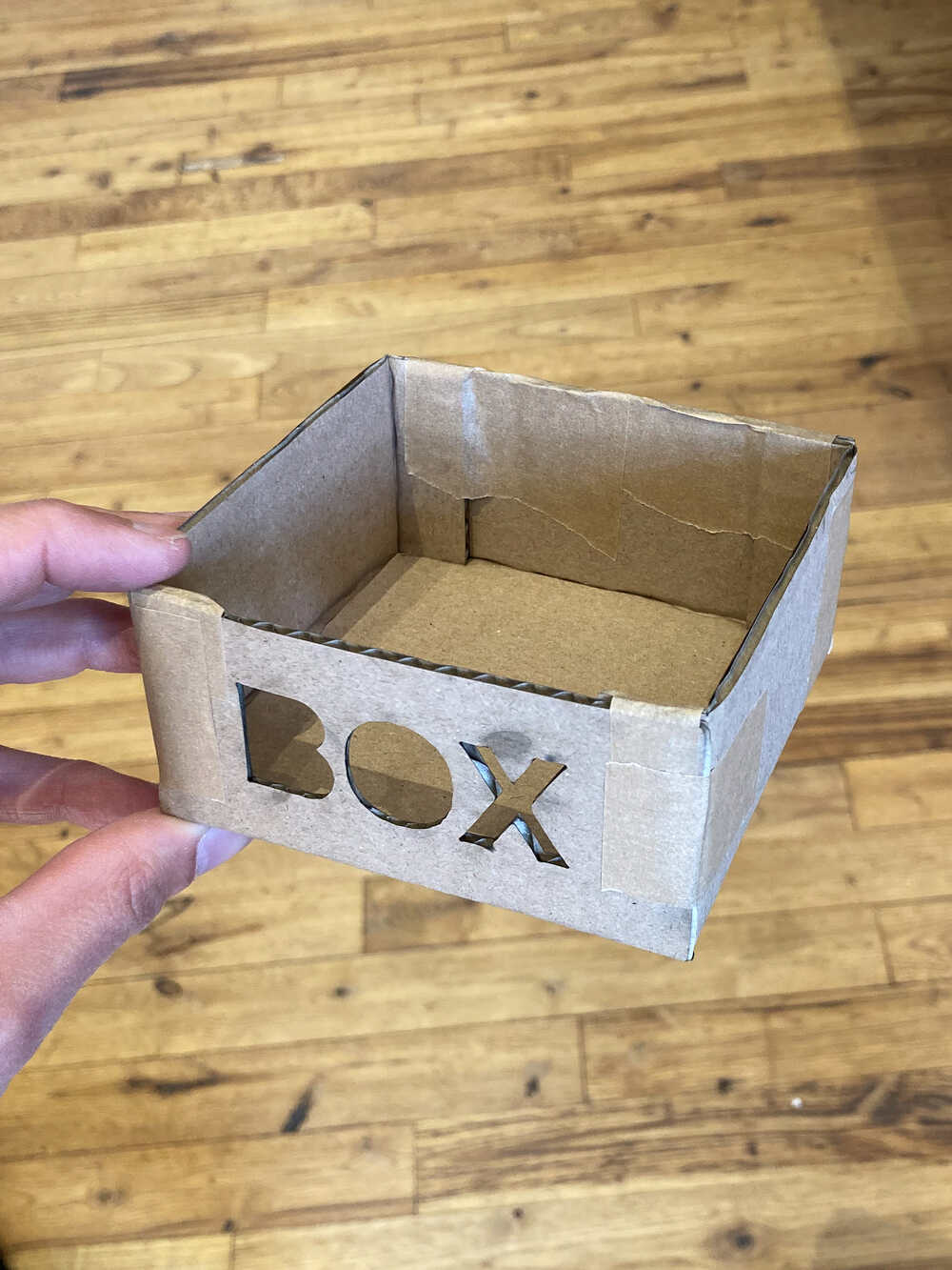
- Fiberglass applied around a cardboard box, left curing as-is without external pressure
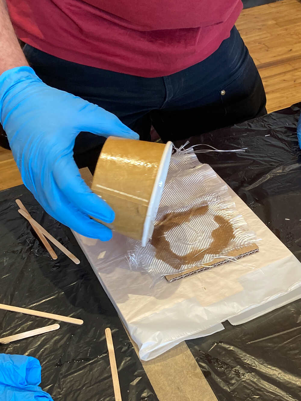
When covering the box it was quite difficult to get the fiberglass to stick to the box in places where it was bending around corners.
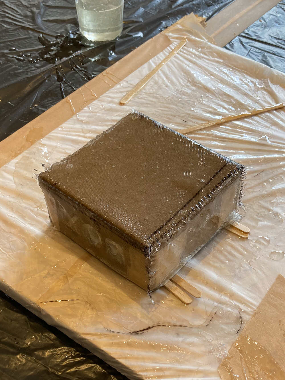
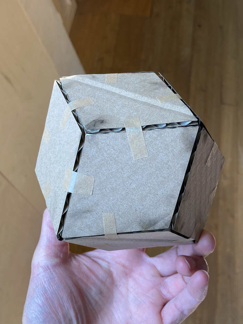
After a weekend of curing the objects looked like this:
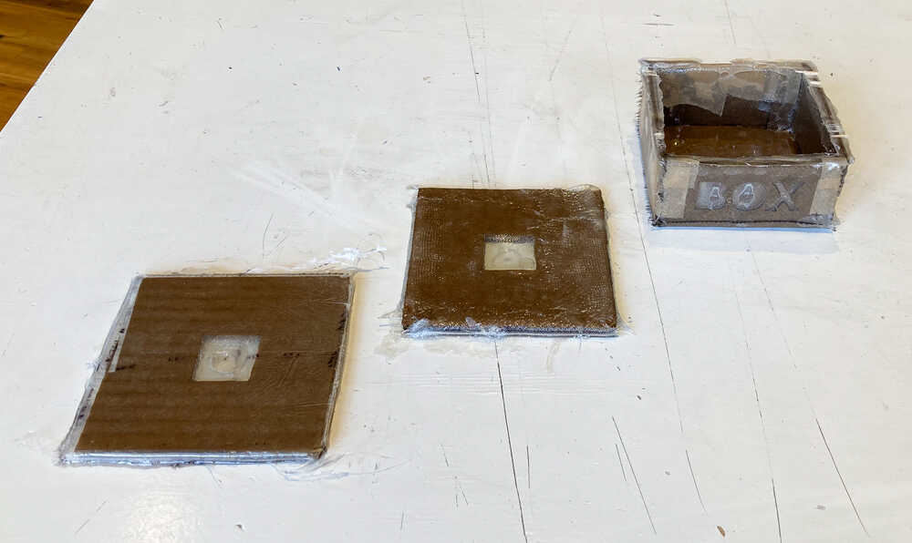
The surface of the square which was pressed between wood plates turned out much smoother but strength-wise the two squares feel similar. When doing the box it was hard to get the fiberglass well positioned at corners and as a consequence all edges turned out pretty rough.
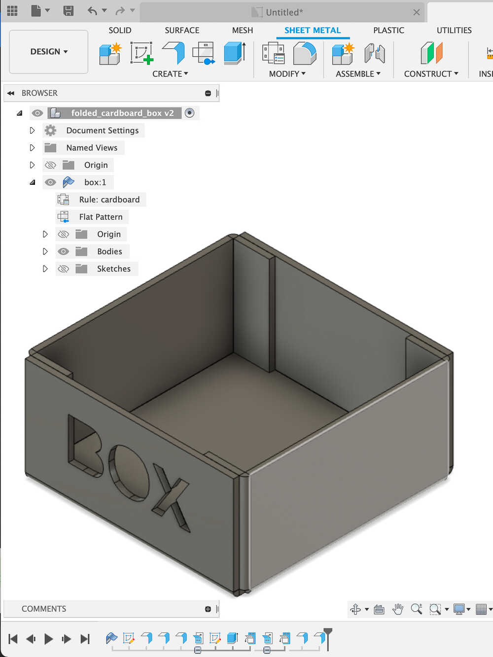
Folded cardboard box 
To create the box for experiment 3. of the group assignment I tried out the sheet metal section in fusion 360.
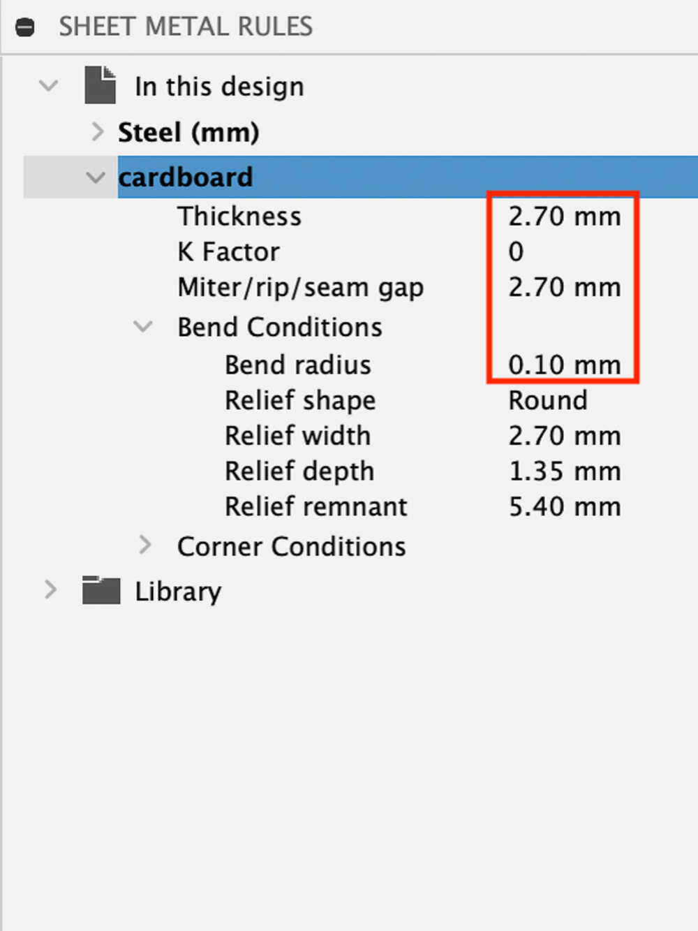
The default sheet metal rules are for metals. To make them work for cardboard I adjusted a couple of parameters:
- set
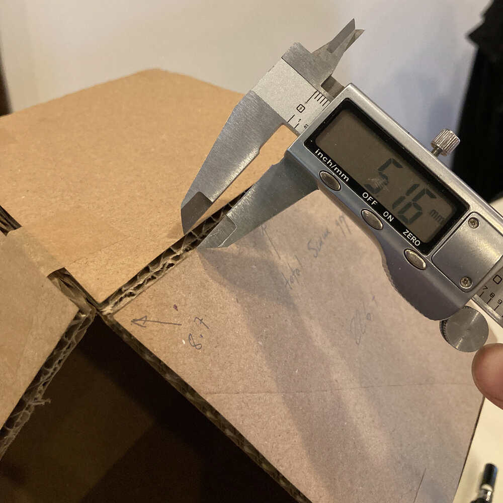
Thicknessto cardboard thickness - set
K Factorto zero - set
Bend radiusto a small value (0.1mm)
Once I watched Fusion 360 Sheet Metal for Beginners it was pretty easy to create a simple object like my cardboard box.
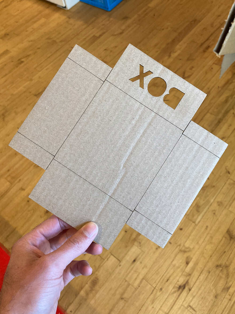
For easier folding, in LightBurn (Laser cutter control software), I selected a profile to cut only half-way through for the folding lines.
Rhombic dodecahedron 
When I saw this video of Adam Savage building a Rhombic dodecahedron I was intrigued by this solid. This week I decided to make one myself.
First prototype
The solid consists of 12 rhombic faces. The long diagonal length of each rhombus is exactly √2 times the short diagonal length.
I started by drawing a rhombus in fusion and cutting 12 of them out of cardboard using the laser cutter. Then I taped the faces together to form the solid.
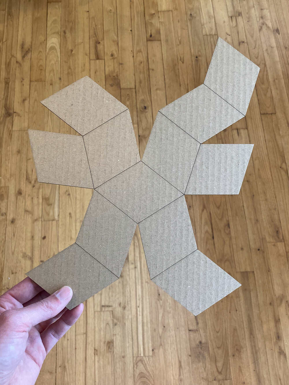
Once I had my first solid I thought It would be neat to cut out a net instead of single rhombi. That way it would be a single cutout and some of the faces would be attached together by a bend.
In fusion I copied the initial rhombus 12 times and then aligned them to form the net which I saw on wikipedia
Make one out of composite
As I understand the most common way to work with composite is to create a 1-way or 2-way mould. But what if you want to create a big object? On the shopbot it’s possible to make moulds which are quite bit in X and Y but the Z height and the tool length limit the mould depth to ~ 100mm or so.
I decided to try another approach: Create a cardboard object and then cover it with cotton fabric and epoxy.
First I created a cardboard dodecahedron from a laser cut net as I did for the prototype just that this time I made it bigger.
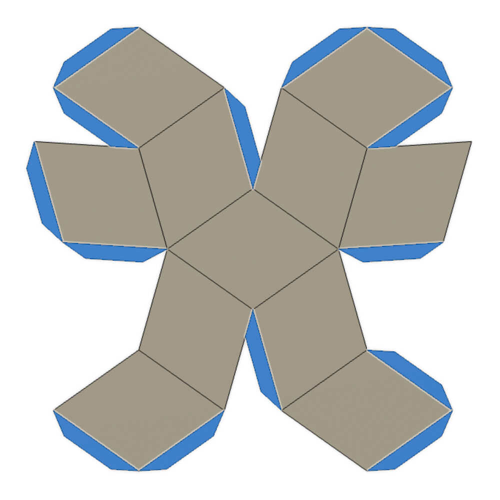
Then It was time to cut the fabric to wrap abound the object. I decide to cut the fabric on the laser cutter too. I took the net in fusion as a starting point and made a couple of modifications:
- Make the dodecahedrons slightly bigger (long diagonal
+8.7mm) to account for the space between faces - Add material between faces so that the fabric overlaps (blue part in design below)
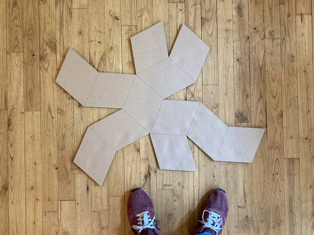
To see if the “skin” fits on the solid I made a try-cut from packaging paper.
Hard to align skin based on outline
I tried to wrap the “skin” around the solid but it was quite hard to get things aligned having only the “skin” outline. To make alignment easier I did draw the lines separating faces and overlaps on the paper with a marker.
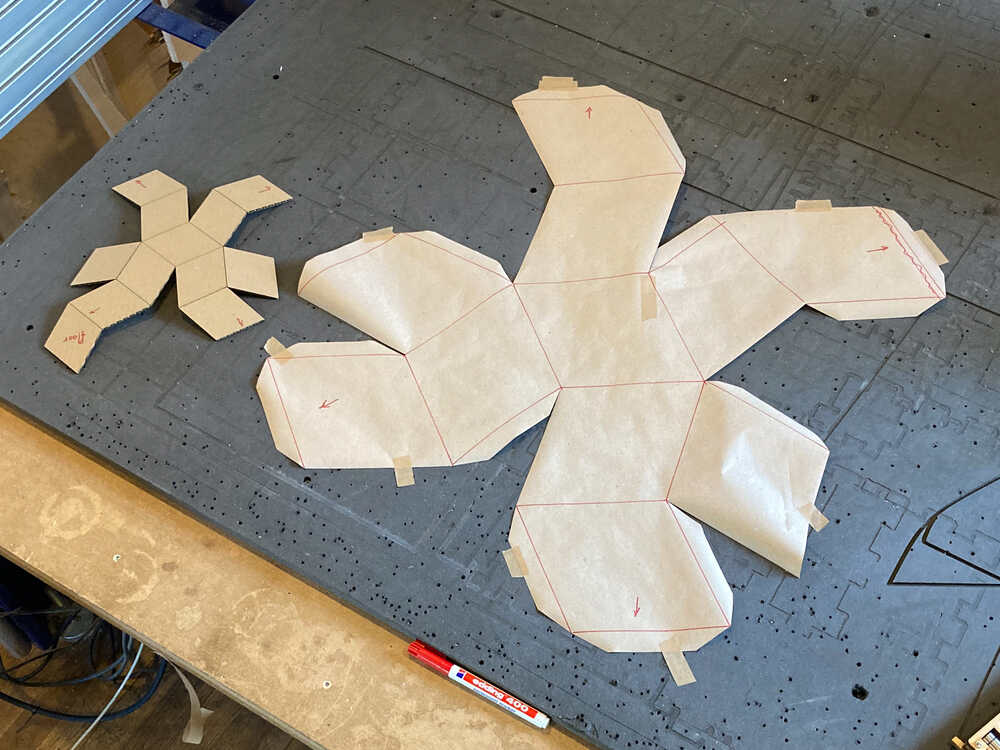
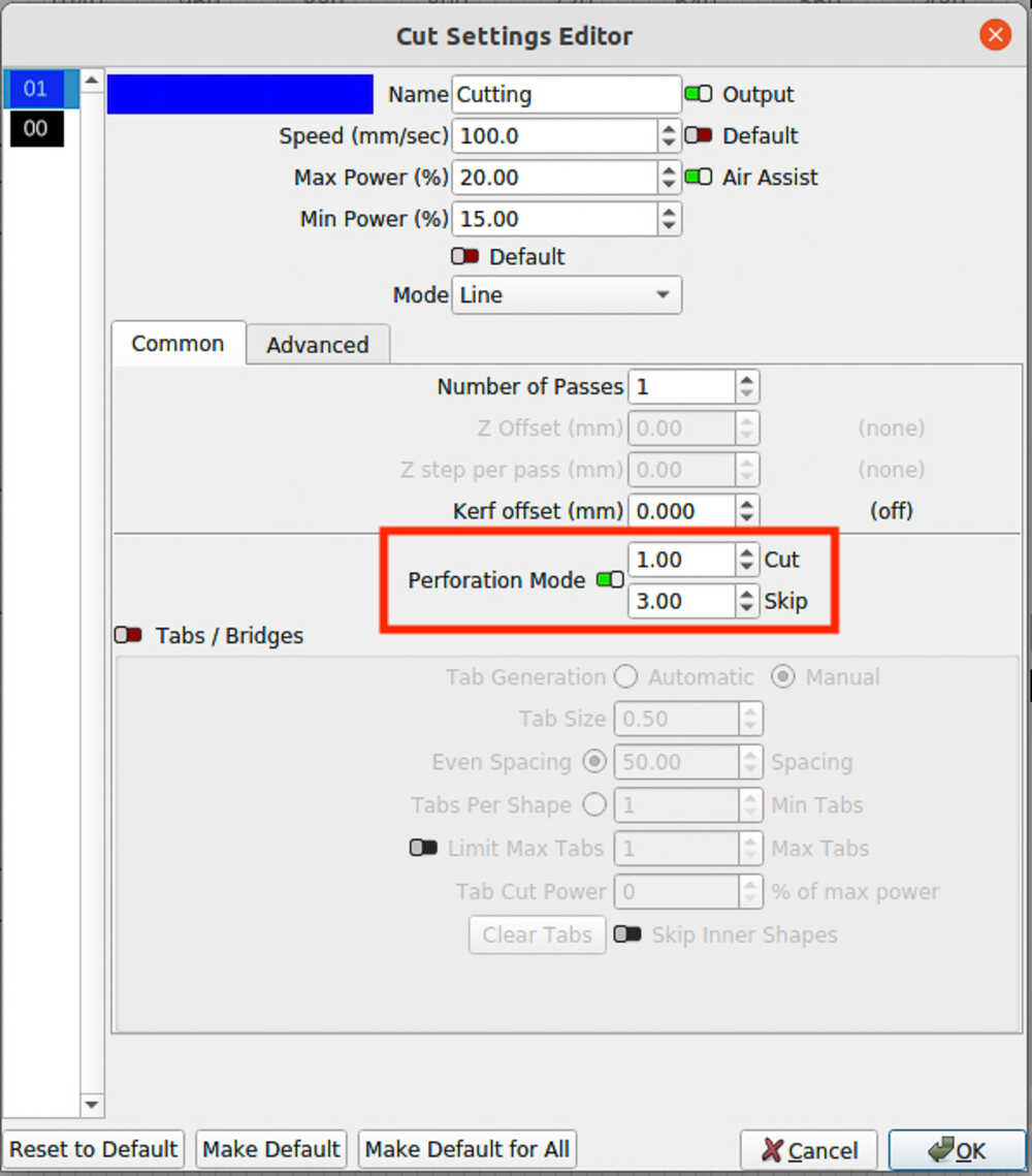
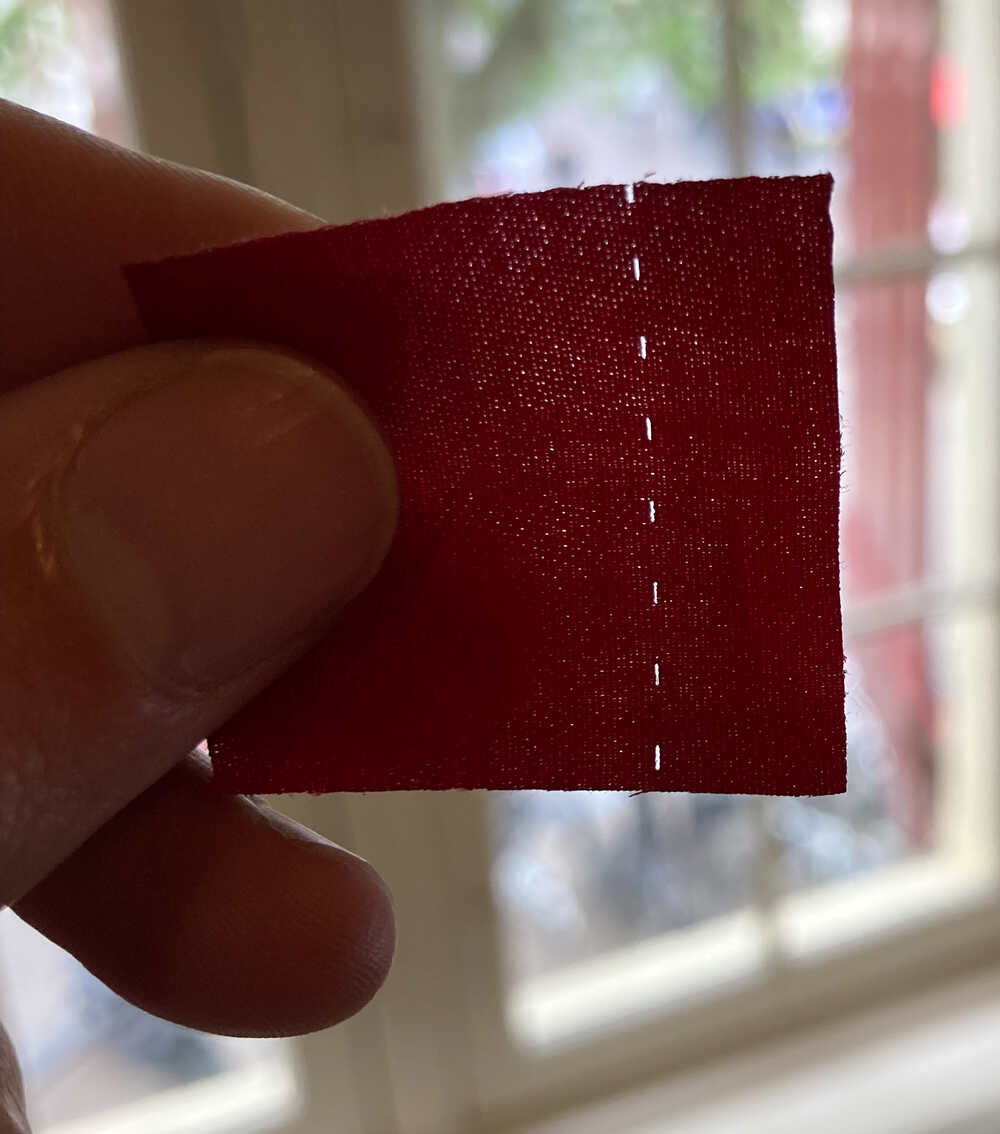
Once I had this extra lines it was much easier to position the paper and it did fit well around the solid :-) At this point I was ready to cut the fabric. To avoid having to draw lines on the fabric like I did on the paper I configured LightBurn (laser control program) to perforated along these lines.
When I did the box in the group assignment it was hard to get the fiberglass aligned well. This time I decided to put the fabric in place beforehand so that when I add epoxy the alignment is already done.
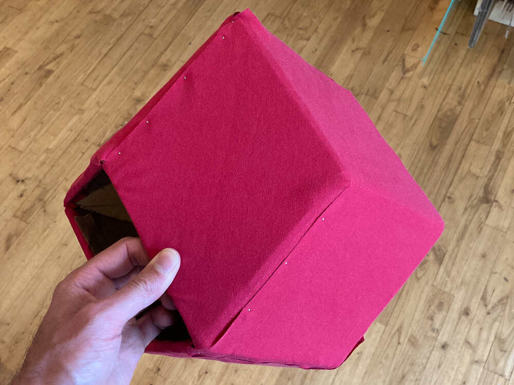
Putting the fabric around the cardboard solid took quite a while but finally I managed to get everything aligned quite well using tape and pins to keep it in place.
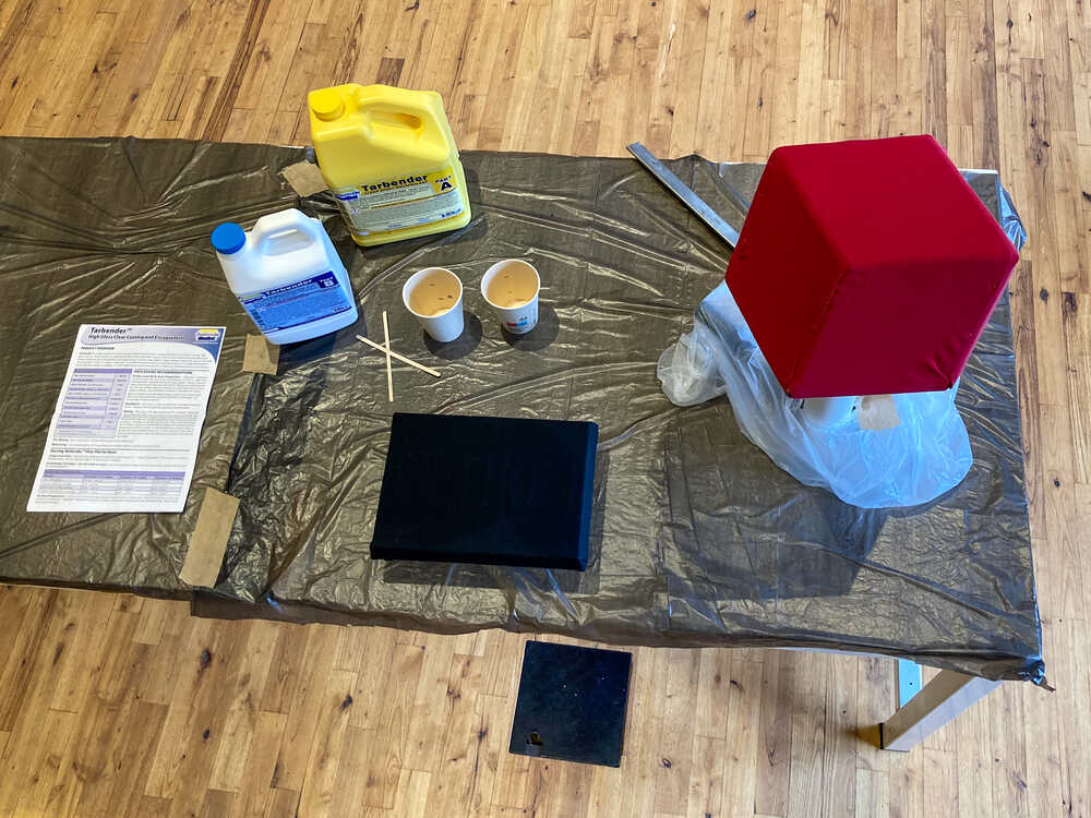
The next day I prepared everything to cover my shape in epoxy. The box I did in the group assignment did stick to the substrate once it was cured because I didn’t prepare a proper setup for the box to dry ahead of time. I learned from the mistake and took my time to prepare everything well this time.
corners
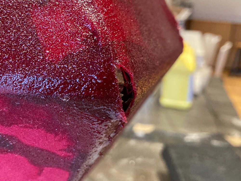
The overlaps I added to the fabric helped to make nice transitions between faces. Some of the corners turned out nice but others didn’t. If I’m going to cut one more fabric “skin” I will take the time to experiment with more/different overlaps in the corners to create a neater result
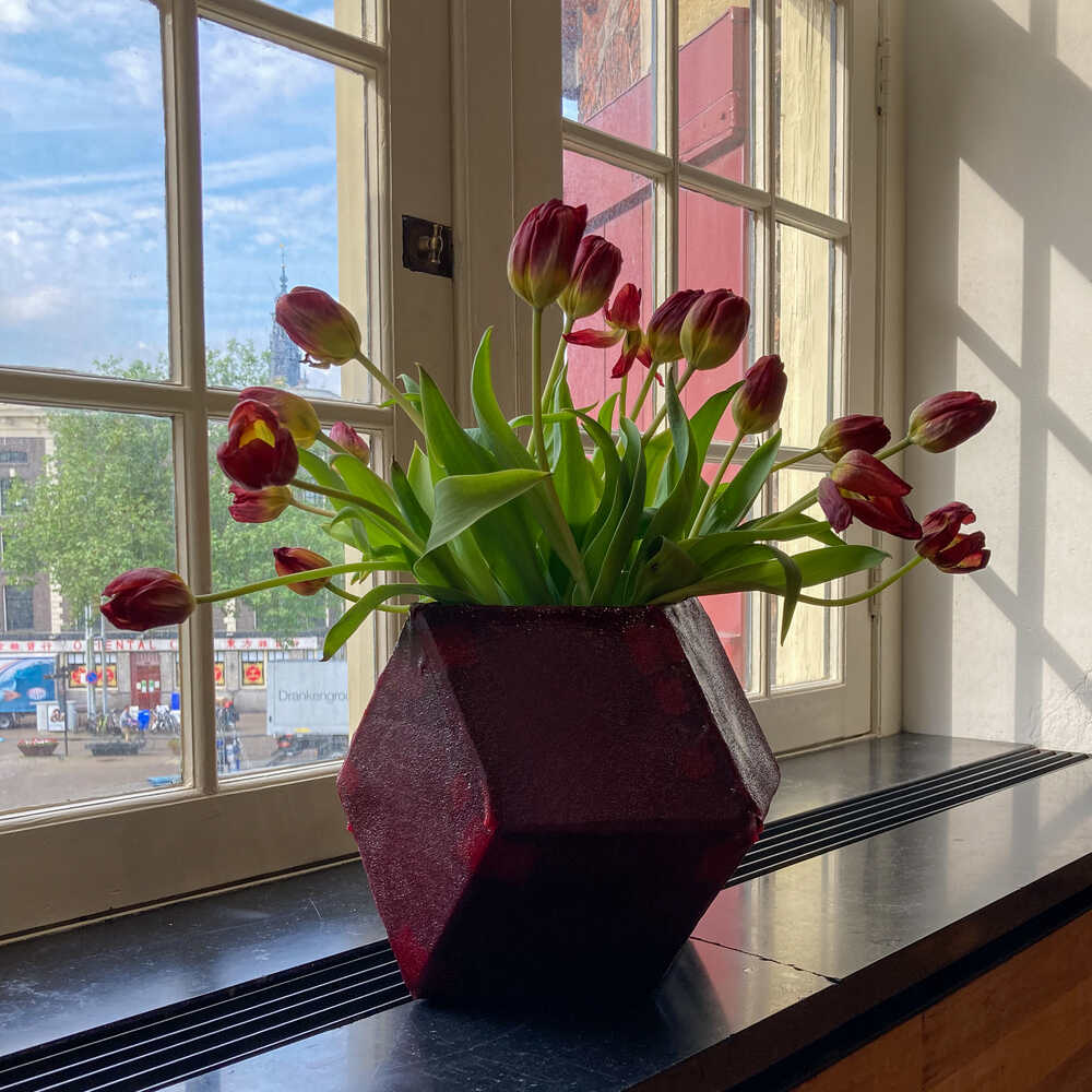
This is the final result after curing:
Wireless motor control 
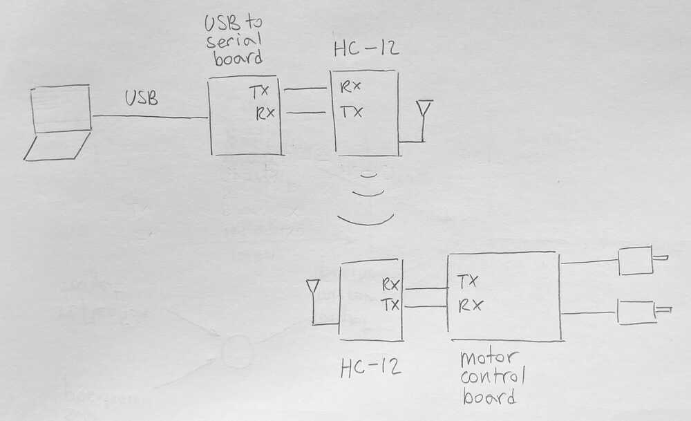
Last week I made a board to control stepper motors for my final project. This week I want to control the motor control board wirelessly. I’m going to use HC-12 wireless serial transceiver modules to send commands to move the motors.
Protocol
I came up with a simple serial protocol to send motor move commands:
AXIScan beH(heading) orP(pitch)DIRECTIONcan be+or-ANGLEconsists of two digits which are sent as characters- The command is terminated with
\n
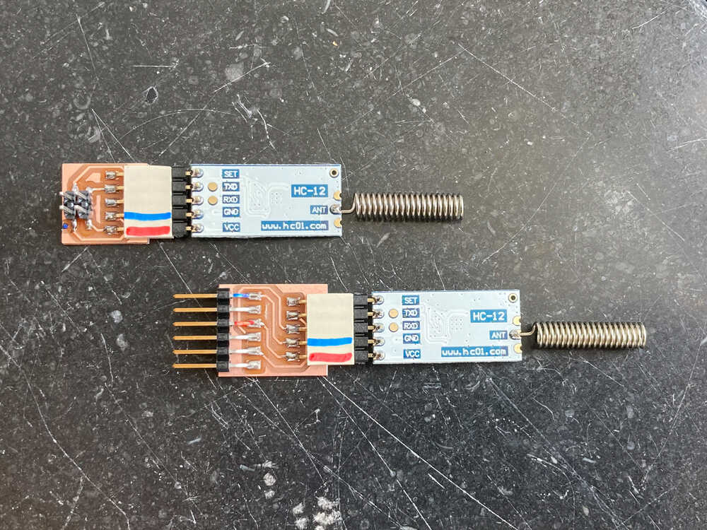
HC-12 adapter boards
I made small adapter boards to easily attach the HC-12 radio modules to FTDI and the motor control board.
Demo
This is my test setup to control the motor remotely:
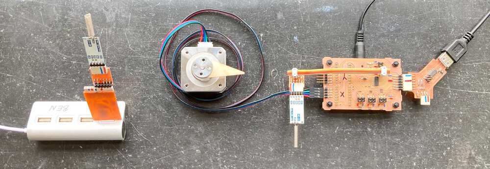
In the video I send commands from my computer to the motor control board wirelessly:
Retrospective
It was really interesting to experiment with composites. I really like the idea of building a cardboard structure and then making it strong and waterproof by covering it with a reinforcement and epoxy. This makes it possible to make rather big structures with simple tools. I found this cool page where Steven shows how he built a bike trailer with this procedure.
I expected it to be more difficult to set up wireless communication but the HC-12 board makes wireless serial communication super easy.