Zoetrope
During the machine building week our group decided to make a Zoetrope machine. It will draw 24 pictures in a circle and will project them on a wall after finishing. On the group page) you can see what we did. Below is my personal work during this week.
Table and Disk Design
To start with, my first focus was to design the mechanics. I am the mechanical engineer after all. Our idea had to be translated to something physical using materials that were available either at Waag or at my own workshop. So the work was a bit of back and forth designing in fusion and collecting and making parts on the fly. Below there’s a first draft in fusion how it should look like.
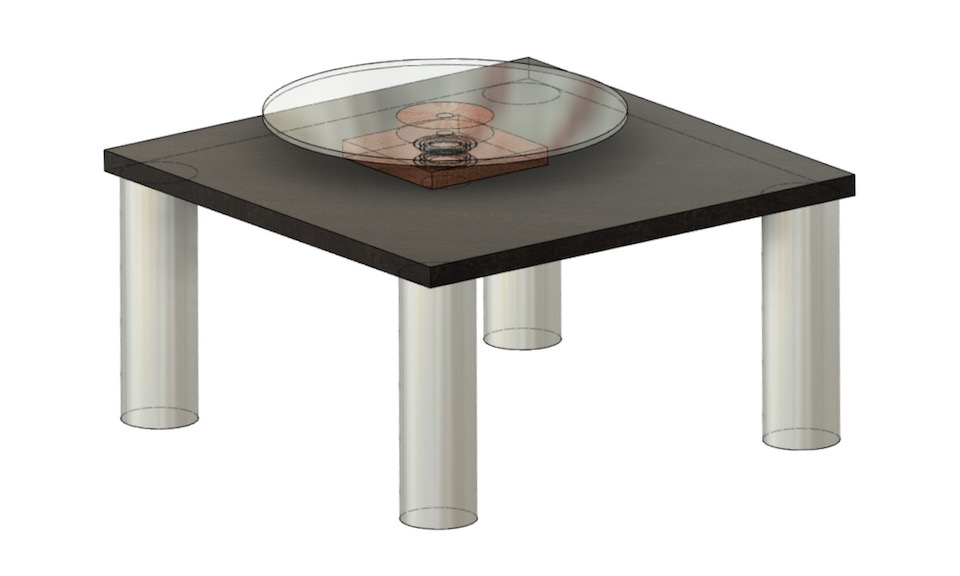
The parts I used are some left over plywood, 4 legs that were left over from a furnace I modified in the past and some old bearings I had laying around. Re-use is the highest level of recycling. :-) The transparent disk was cut out with the laser cutter at Waag. The housing for the main bearing was made by hand with a hole saw and a bit of adjustment using a file and sanding paper to get the right fit. The axis was a left over shaft from Waag.
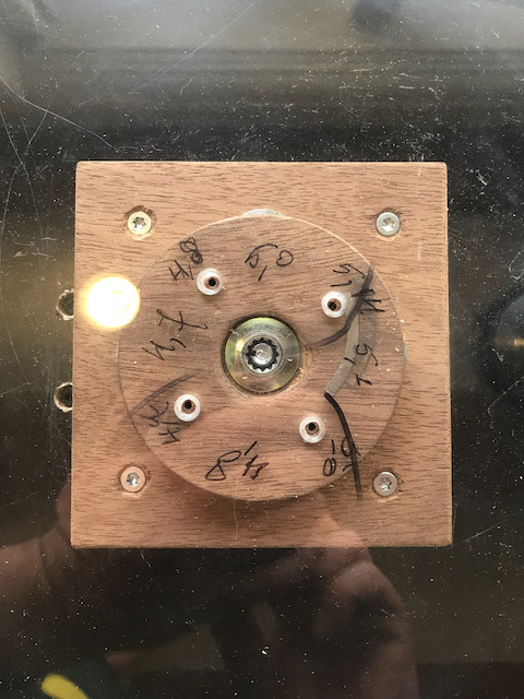
The top surface of the disk should rotate axactly in the same plane, but it turned out, it didn’t. I knew already that the construction of the disk mount wasn’t that precise, but it was worse than I thought. It turned out that the PMMA disk material was not very uniform in thickness. Below you see the measurements and the way I adjusted the mount by using some small shims between the wooden mounting disk and the drawing disk.
| measurment | shims |
|---|---|
 |
Arm Mechanism
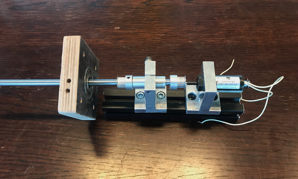
The arm mechanism gave me a bit of trouble. The idea was to use a solenoid that lifts the whole arm assembly, but this means the bearing should be able to have 2 degrees of freedom: sliding up and down and rotating. The linear bearings that I found at Waag did have too much friction in the rotation, so that didn’t work. The small ball bearings I had myself could work, they had a nice fit with just enough play around the shaft. But the problem was that I needed two of them to make make a fixed rotational axis and aligning two bearings in this set-up proved too unpredictable.
Finally I turned into combining them. The outside of the linear bearing was 1 mm smaller than a bearing I found. With a thin sheet of metal of 0,5 mm I was able to fill exactly the gap and center the linear bearing in the ball bearing.
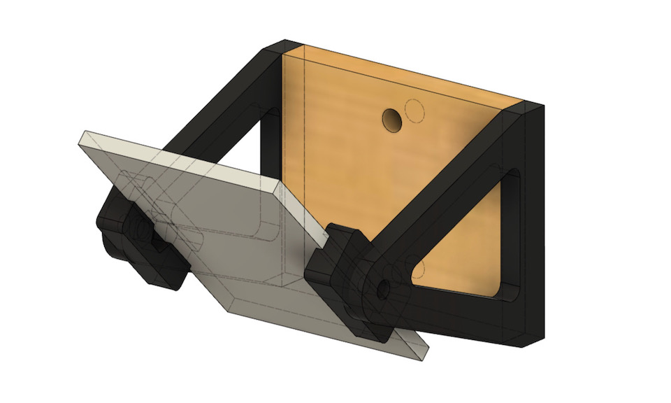
Lenses and Projection Mirror
From a second hand store I bought an old slide projector for € 10,- so we could use the lenses for the projection. It took some experimenting to understand the function of the different lens parts and to define the right distances to the rotating disk. The construction was made of standard construction extrusions and some simple makeshift parts like a tube clamp and a drain pipe. The mirror needed something more advanced, so I quickly last minnute 3D printed some parts to mount a small mirror that one of us brought in.